Investigated Scenarios with PID Controllers and FMUs
Explore various cases and scenarios involving PID controllers and Functional Mockup Units (FMUs) in a comparison between LS-DYNA and Scilab models. Investigate the effects of different PID controller parameters on the system's behavior, utilizing mass-spring-damper setups and 2D coordinate systems. Understand the implications of PID controller tuning on system performance and response.

Download Presentation

Please find below an Image/Link to download the presentation.
The content on the website is provided AS IS for your information and personal use only. It may not be sold, licensed, or shared on other websites without obtaining consent from the author. If you encounter any issues during the download, it is possible that the publisher has removed the file from their server.
You are allowed to download the files provided on this website for personal or commercial use, subject to the condition that they are used lawfully. All files are the property of their respective owners.
The content on the website is provided AS IS for your information and personal use only. It may not be sold, licensed, or shared on other websites without obtaining consent from the author.
E N D
Presentation Transcript
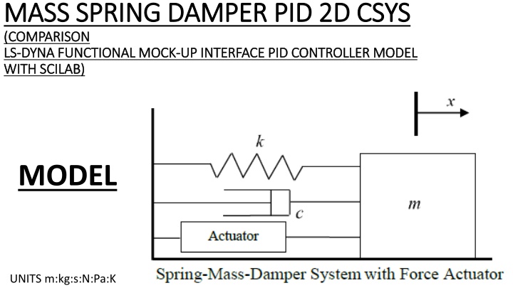
MASS SPRING DAMPER PID 2D CSYS MASS SPRING DAMPER PID 2D CSYS (COMPARISON (COMPARISON LS LS- -DYNA FUNCTIONAL MOCK DYNA FUNCTIONAL MOCK- -UP INTERFACE PID CONTROLLER MODEL UP INTERFACE PID CONTROLLER MODEL WITH SCILAB) WITH SCILAB) MODEL UNITS m:kg:s:N:Pa:K
SCENARIOS INVESTIGATED CASE 0 : NO FMU NO PID CONTROLLER CASE 1 : 1F : Kp = 300.0 Ki= 0.0 Kd=0.0 CASE 2 : 1G : Kp = 300.0 Ki= 0.0 Kd=10.0 CASE 3 : 1H Kp = 30.0 Ki= 70.0 Kd=0.0 CASE 4 : 1H Kp = 350.0 Ki= 300.0 Kd=50.0 Only for FMI non-Wrapper, LSDYNA is Master, FMU is Slave, no TCP-IP
CASE 0 : SCILAB NO PID CONTROLLER
CASE 0 : LS-DYNA NO FMU NO PID CONTROLLER Mass 1 kg Spring 20 N/m Damper 10 N*s/m PID 150 PID 201 PID 200 1 N Force Step Load Fixed Fixed
CASE 1 : LS-DYNA WITH FMU NON WRAPPER Kp 300.0 Ki=0.0 Kd=0.0 GEN COSIM 2 1 C:\...\FMI_Manager_v2\fmu_tpl\fmi_udf.c -file- 3
CASE 1 : LS-DYNA WITH FMU NON WRAPPER Kp 300.0 Ki=0.0 Kd=0.0 (output DY ) (setpoint CY ) (force out) (force input) NID45 Y=1.0m Kp=300.0 Ki=0.0 Kd=0.0
CASE 2 : LS-DYNA WITH FMU NON WRAPPER Kp -300.0 Ki=0.0 Kd=10.0 GEN COSIM 2 1 C:\...\FMI_Manager_v2\fmu_tpl\fmi_udf.c -file- 3
CASE 2 : LS-DYNA WITH FMU NON WRAPPER Kp=300.0 Ki=0.0 Kd=10.0 (output DY and VY ) (setpoint CY ) (force out) (force input) NID45 Y=1.0m Kp=300.0 Ki=0.0 Kd=10.0
CASE 3 : LS-DYNA WITH FMU NON WRAPPER Kp=30.0 Ki=70.0 Kd=0.0 GEN COSIM 2 1 3 C:\...\FMI_Manager_v2\fmu_tpl\fmi_udf.c -file- NB This C code needs to be inserted in file.
CASE 3 : LS-DYNA WITH FMU NON WRAPPER Kp=30.0 Ki=70.0 Kd=0.0 (force out) (output DY ) (setpoint CY ) NID45 Y=1.0m Kp=30.0 Ki=70.0 Kd=0.0
CASE 3 : LS-DYNA WITH FMU NON WRAPPER Kp=350.0 Ki=300.0 Kd=50.0 GEN COSIM 2 1 3 C:\...\FMI_Manager_v2\fmu_tpl\fmi_udf.c -file- NB This C code needs to be inserted in file.
CASE 4 : LS-DYNA WITH FMU NON WRAPPER Kp=350.0 Ki=300.0 Kd=50.0 (force out) (output DY Output VY ) (setpoint CY ) NID45 Y=1.0m Kp=350.0 Ki=300.0 Kd=50.0