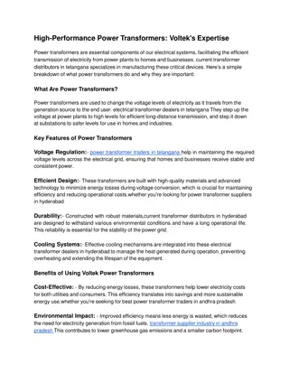
Introduction to Transformer Cooling System Design

The design and importance of a cooling circuit in transformers are discussed in this article by Prof. VG Patel. Learn about the impact of temperature on insulation, dielectric strength, and mechanical properties, and the factors influencing the temperatures in a transformer system. Understanding how to dissipate heat effectively is crucial in maintaining the transformer's efficiency and lifespan.

Uploaded on Mar 05, 2025 | 0 Views
Download Presentation

Please find below an Image/Link to download the presentation.
The content on the website is provided AS IS for your information and personal use only. It may not be sold, licensed, or shared on other websites without obtaining consent from the author.If you encounter any issues during the download, it is possible that the publisher has removed the file from their server.
You are allowed to download the files provided on this website for personal or commercial use, subject to the condition that they are used lawfully. All files are the property of their respective owners.
The content on the website is provided AS IS for your information and personal use only. It may not be sold, licensed, or shared on other websites without obtaining consent from the author.
E N D
Presentation Transcript
Design of Cooling Circuit PRESENTED BY PROF. VG PATEL VG PATEL
TRANSFORMER ENCYCLOPAEDIA DESIGN OF COOLING CIRCUIT COOLING SYSTEM DESIGN VG PATEL Wednesday, March 5, 2025 2
TRANSFORMER ENCYCLOPAEDIA DESIGN OF COOLING CIRCUIT INTRODUCTION The transformer is a static device which converts energy at one voltage level to another voltage level. During this process at energy transfer, losses occur in the windings and core of the transformer. These losses appear as a heat. Some times loose electrical connection Indies the transformer leading to a high contact resistance, cause higher temperature, excessive temperature due to heating at curb bolts, which are in the path of stray field can damage gaskets. The heat generated due to all these losses must be dissipated without allowing the core, winding and structural parts to reach a temperature which will cause deterioration of insulation. VG PATEL Wednesday, March 5, 2025 3
TRANSFORMER ENCYCLOPAEDIA DESIGN OF COOLING CIRCUIT If the insulation is subjected to temperatures higher than the allowed for a long time, it loose insulating properties, in other words the insulation gets aged, severely affecting the trans- former life. There are two principle characteristics of insula- tion: Dielectric strength and mechanical strength. The dielectric strength at insulation aged in oil remains high up to a certain temperature after which it drops rapidly. At this point the insulation material become brittle and looses its mecha- nical strength. Thus, it is primarily the mechanical strength which gets affected by the higher temperatures and ageing, which in turn affects the dielectric strength. Hence, the dielectric strength alone can not always be depended upon for judging the effect of temperatures on the insulation. VG PATEL Wednesday, March 5, 2025 4
TRANSFORMER ENCYCLOPAEDIA DESIGN OF COOLING CIRCUIT The temperatures depends on the ambient temperature, transformer design, loading conditions and cooling provided. The limits of oil temperature rise and winding temperature rise are specified in the international standards. As the ambient temperature varies from one country to another, the limit could be different for different countries. For example in IEC-60076-2 (second edition: 1993), a maximum ambient temperature at 40o C is specified with a limit of top oil temperature rise at 600 C values of maximum oil and winding VG PATEL Wednesday, March 5, 2025 5
TRANSFORMER ENCYCLOPAEDIA DESIGN OF COOLING CIRCUIT In a country where the maximum ambient temperature is 500 C, the top oil temperature rise limit may be correspondingly reduced to 500 C. if the installation site is more than 1000 m above the sea level, the allowable temperature rise for transformer is reduced as per the guidelines given in the standards because of the fact that air density reduces with the increase in attitude lowering the effectiveness of cooling. Attitude basically affects the connective heat transfer and not the radiation. A corresponding reverse connection is applied when the attitude of factory location is above 1000m and the attitude of installation is below 1000m. VG PATEL Wednesday, March 5, 2025 6
TRANSFORMER ENCYCLOPAEDIA DESIGN OF COOLING CIRCUIT The coolant used in transformers is: 1) air (2) oil The transformer using air as the coolant are called dry type transformer while transformers which use oil as the coolant are called oil immersed transformers. In dry type transformer, the heat generated is conducted across the core and windings to be dissipated from the outer surface of windings to the surrounding air through convection. In the case of oil immersed transformer, the heat produced inside the core and the windings is conducted across them to their surfaces. This heat is transferred by the oil to the walls of the tank through connection; finally, the heat is transferred from the tank walls to the surrounding air by radiation and convection. VG PATEL Wednesday, March 5, 2025 7
TRANSFORMER ENCYCLOPAEDIA DESIGN OF COOLING CIRCUIT Modes of Heat Transfer: The heat transfer mechanism in transformer takes place by three modes, viz conduction, convection and radiation. In the oil cooled transformers, convection plays the most important role and conduction the least important. Conduction: Almost all the types of transformers are either oil or gas filled, and heat flows from the core and windings in to the cooling medium. From the core, heat can flow directly but from winding it flows through the insulation provided on the winding conductor. In large transformers at least one side of insulated conductor is exposed to the cooling medium, and the heat flows through a small thickness of the conductor insulation. But in small transformers the heat may have to flow through several layers of copper and insulation before reaching the cooling medium. VG PATEL Wednesday, March 5, 2025 8
TRANSFORMER ENCYCLOPAEDIA DESIGN OF COOLING CIRCUIT The temperature drop across the insulation due to the conduction heat transfer mechanism can be calculated by the basic thermal law: = X RT Where is a heat flow (power loss) in W and RT is thermal resistance in 0C/w. The thermal resistance is given by RT = ti / kXA Where ti is the insulation thickness in m, A is cross sectional Area in m2, and k is thermal conductivity in W/ cm0 C). If denotes heat flux per unit transfer area, the temperature drop across the insulation can be rewritten as o = X ti / k It should be noted that the thermal conductivity of oil impregnated paper insulation is temperature dependent and its proper value should be taken in the calculations. VG PATEL Wednesday, March 5, 2025 9
TRANSFORMER ENCYCLOPAEDIA DESIGN OF COOLING CIRCUIT Radiation: Anybody, at a raised temperature compared to its surrounding, radiates energy in the form of waves. The heat dissipation from a transformer tank occurs by means of both radiation and natural convection. The cooling of radiators also occur by radiation, but it is for less as compared to that by convection, because of closeness of radiator fins, the entire radiator surface does not participate in the heat transfer mechanism by radiation, thus, the effective area for radiation cannot be taken as outside envelop surface of the radiator. Therefore, for the case of tank with radiators connected to it, actual radiating surface area is that area on which a highly stretched string would lie. The emissive of the radiating surface affects the radiation. VG PATEL Wednesday, March 5, 2025 10
TRANSFORMER ENCYCLOPAEDIA DESIGN OF COOLING CIRCUIT Surface emissivity is a property, which depends on several factors like surface finish, type of paint applied on the surface etc. When the emissivity factor is less than unity, the effective radiating surface is correspondingly less (as indicated by above equation) .for tank and radiators painted with grey colour, having emissivity at 0.95, the effective radiating area is usually assumed so that of outside envelope without introducing much error. VG PATEL Wednesday, March 5, 2025 11
TRANSFORMER ENCYCLOPAEDIA DESIGN OF COOLING CIRCUIT Convection: The oil being a liquid has one important mechanical property that its volume changes with temperature and pressure. The change of volume with temperature provides the essential connective or thermo siphon cooling. The change of volume with pressure affects the ambient of transferred vibrations from core to tank. The heat dissipation from the core and winding occurs mainly due to convection. When a belated surface is immersed in a fluid, heat flows from the surface to the cooling medium. Due to increase in fluid temperature, its density (or specific gravity) reduces. The liquid (oil) in oil cooled transformers rises upwards and transfer its heat to outside ambient through tank and radiators. The rising oil is replaced by the colder oil from the bottom, and thus the continuous oil circulation occurs. VG PATEL Wednesday, March 5, 2025 12
TRANSFORMER ENCYCLOPAEDIA DESIGN OF COOLING CIRCUIT The connective heat transfer is expressed by the relationship: = hA (T surface T fluid) Where is the heat flow in w, h is heat transfer coefficient in w/ m20C, A is the surface area in m2, and temperatures. T surface and T fluid are in 0C. Since h depends on both geometry as well as fluid properties, it estimation is very difficult. The heat dissipation from the transformer tank to ambient air occurs similarly but the warmed air after cooling does not come back and its place is occupied by new quantity fresh air. In the case of Tank, heat dissipation by convection and radiation mechanism are comparable since the surface area available for the connective cooling is same as that for the radiation cooling. The heat dissipated by tank through the convection and radiation is also usually calculated by empirical relations in which the resultant effect of both the mechanism is taken in to account. VG PATEL Wednesday, March 5, 2025 13
TRANSFORMER ENCYCLOPAEDIA DESIGN OF COOLING CIRCUIT COOLING ARRANGMENTS For Dry Type Transformers: The cooling methods used for dry type transformers are: Air Natural: This method uses the ambient air as the cooling medium. The natural circulation of surrounding air is utilized to carry away the heat generated by natural connection. A sheet metal enclosure is used to product the windings against mechanical damage. This method is used for small low voltage transformers. However the development of insulating material like glass and silicon resin class C materials which can withstand higher temperature (1500 C) makes the method suitable for transformer rating up to 1.5 KVA. The high rating transformers are used in special applications like in mines where fire is great hazard. VG PATEL Wednesday, March 5, 2025 14
TRANSFORMER ENCYCLOPAEDIA DESIGN OF COOLING CIRCUIT 2. Air Blast (AB) Cooling by normal circulation of air becomes inadequate to dissipate heat from large transformers and hence for circulation of air (air blast) is employed in order to keep the temperature rise within limits. The forced air circulation improves the heat dissipation. In this method, the transformer is cooled by a continuous blast of cooling air forced through the core and windings. The air blast is produced by external fans. The improvement in heat dissipation caused by air blast allows higher specific loadings to be used in dry type transformers. The use of specific loading result in lower size for the transformers. The air supply must be filtered to prevent accumulation of dust particles in the ventilating ducts. VG PATEL Wednesday, March 5, 2025 15
TRANSFORMER ENCYCLOPAEDIA DESIGN OF COOLING CIRCUIT For Oil Immersed Transformers: 1.1. ONAN / OA cooling In small rating transformers, the tank surface area may be able to dissipate heat directly to the atmosphere; while the bigger rating transformers usually require much larger dissipating surface in the form of radiators/ tubes mounted directly on the tank or mounted on a separate structure. If the number of radiators is small, they are preferably mounted directly on the tank so that it results in smaller overall dimensions. When number of radiators is large, they are mounted on a separate structure and the arrangement is called as radiator bank. The radiators are mounted on headers, which are supported from the ground. In this case, strict dimensional control of pipes and other fittings is required in order to avoid oil leakages. VG PATEL Wednesday, March 5, 2025 16
TRANSFORMER ENCYCLOPAEDIA DESIGN OF COOLING CIRCUIT Oil is kept in circulation by the gravitational buoyancy in the closed-loop cooling system as shown in figure. The heat developed in active parts is passed on to the surrounding oil through the surface transfer (convection) mechanism. The oil temperature increases and its specific gravity drops, due to which it flows upwards and then in to the coolers. The oil heat gets dissipated along the colder surfaces of the coolers which increase its specific gravity, and it flows downwards and enters the transformer tank from the inlet at the bottom level. Since the heat dissipation from the oil to atmospheric air is by natural means (the circulation mechanism for oil is the natural thermo-siphon flow in the cooling equipments and windings), the cooling is termed as ONAN (Oil Natural and Air Natural) or OA type of cooling. VG PATEL Wednesday, March 5, 2025 17
TRANSFORMER ENCYCLOPAEDIA DESIGN OF COOLING CIRCUIT VG PATEL Wednesday, March 5, 2025 18
TRANSFORMER ENCYCLOPAEDIA DESIGN OF COOLING CIRCUIT In the arrangement consisting of radiator banks, higher thermal head can be achieved by adjusting the height of support structures. The thermal head can be defined as the difference between the centers of gravity of fluids in the tank and radiator bank. Although it is difficult to get higher thermal head for the case of tank mounted radiators, reasonable amount of thermal head is achieved by the arrangement shown in fig. When the radiators are mounted at higher height, the buoyancy effect on the cooling loop increases resulting in increase of the rate of oil flow and heat dissipation in the cooling equipment. However, it is to be noted that the increase in flow are results in increased fractional pressure loss, thereby offsetting the thermal head gained by the height difference. VG PATEL Wednesday, March 5, 2025 19
TRANSFORMER ENCYCLOPAEDIA DESIGN OF COOLING CIRCUIT VG PATEL Wednesday, March 5, 2025 20
TRANSFORMER ENCYCLOPAEDIA DESIGN OF COOLING CIRCUIT 1.2. ONAF / FA cooling: As the transformer rating increases, the total loss to be dissipated also increases. One way of increasing the heat transfer is to increase the heat transfer coefficient between the radiator outside surface and air. In this equation, for a radiator T surface corresponds to its outside wall surface temperature. However, the temperature drop across the radiator plate is very small; hence T surface can be considered as the oil temperature itself. If fans are used to blow air on to the cooling surfaces of the radiators, the heat transfer coefficient is significantly increased. For a given set of ambient air temperature and oil temperature, a compact arrangement is possible since less number of radiators is required to cool the oil. This type of cooling is termed as ONAF (Oil Natural and Air Forced) OR FA type of cooling. VG PATEL Wednesday, March 5, 2025 21
TRANSFORMER ENCYCLOPAEDIA DESIGN OF COOLING CIRCUIT If there is a particular case in which either ONAN or mixed ONAN/ ONAF cooling can be specified; the ONAN cooling has the following advantages (although it may take more space): It is more reliable as no cooler controls are involved and it requires less maintenance The cost increase due to extra radiators is, to a large extent, compensated by the reduction in cost due to the absence of fans and control system It is particularly useful when low noise transformers are required. Absence of fans makes it easier to achieve the required low noise level. VG PATEL Wednesday, March 5, 2025 22
TRANSFORMER ENCYCLOPAEDIA DESIGN OF COOLING CIRCUIT There is no cooler loss Winding losses also reduce (although marginally) because of lower winding temperature rise at functions or rated load as compared to the mixed cooling. Most of the time, when load on the transformer is less than its full rating, temperature rise inside the transformer is low and its life increases (gain of life) Thus, in cases where the ONAN rating is 75% or more (it is closer to the ONAF rating), ONAN cooling can be specified instead of mixed ONAM/ ONAF cooling based on cost-benefit analysis. VG PATEL Wednesday, March 5, 2025 23
TRANSFORMER ENCYCLOPAEDIA DESIGN OF COOLING CIRCUIT There are two typical configurations for mounting fans in ONAF cooling. One method is to mount the fans below the radiators, which blow air form bottom to top. Larger capacity fans can be used since it is easy to design the support structures for them. In this system the fans can be either supported directly from the radiators or they can be ground mounted. Care should be taken that the fans mounted on radiators do not produce appreciable vibrations. Usually, sufficient surface or radiators is covered in the air-flow cone created by the fan; the remaining surface is taken to be naturally cooled. In the second method, fans are mounted on the side of radiators. These fans are relatively smaller in size compared to the first arrangement since the number of fans is usually more for this configuration. Both the configurations have their own advantages and disadvantages. Particular section depends on the specific design requirement. VG PATEL Wednesday, March 5, 2025 24
TRANSFORMER ENCYCLOPAEDIA DESIGN OF COOLING CIRCUIT 1.3. OFAF/ FOA cooling: As discussed previously, the flow rate inside the windings under ONAN and ONAF cooling arrangements is governed by the natural balance the viscous resistance and the thermo-siphon pressure head. Normally this flow rate is relatively low. Because of this, the heat carrying (or dissipating) capacity of the oil is low. The heat carrying capacity can be defined as Q = iii CP (T out T in) Where, Q is heat flow in W, iii is mass flow rate in Kg/s, Cp is specific heat in J / (Kg0C), and temperatures Tout and Tin are in 0C for the given transformer oil inlet (T in) and top oil (T out) temperatures, the only way to increase the heat dissipation capability is to increase in. This necessitates the use of an external pump to circulate the oil in high rating transformers. Also, in order to get a higher heat transfer rate, fans have to be always operating at the radiator sections. VG PATEL Wednesday, March 5, 2025 25
TRANSFORMER ENCYCLOPAEDIA DESIGN OF COOLING CIRCUIT This type of cooling is called as OFAF (Oil Forced and Air Forced) or FOA cooling. There are basically two types of pumps designs; axial flow in-line type and radial flow type for circulating oil against low and high frictional head losses respectively. The axial flow type is used with mixed cooling (ONAN/ ONAF/ OFAF) since it offers less resistance when switched off. The radial flow type pumps, which offer very high resistance to oil flow under the switched off condition, are used with oil-to-air heat exchangers (unit cooler arrangement) or oil-to- water heat exchangers in which no natural cooling is provided. The head required to be developed for these two types of compact heat exchange is quite high and the radial flow pump can cater to this requirement quite well. VG PATEL Wednesday, March 5, 2025 26
TRANSFORMER ENCYCLOPAEDIA DESIGN OF COOLING CIRCUIT In OFAF cooling arrangement, when fans are mounted on the sides of radiators, they should be uniformly distributed over the radiator height, whereas for ONAF cooling more fans should be mounted at the top of radiator height. This is because in OFAF condition, the temperature difference between top and bottom portions of radiators is small as compared to that under ONAF condition. When the oil is forced in to the transformer, its flow is governed by the least resistance path as well as the buoyancy. Hence, part of the oil may not enter either windings or core, and may form a parallel path outside these two. Thus, the top oil temperature may reduce because of the mixer of hot oil coming from the windings and the cool oil coming from the pump. VG PATEL Wednesday, March 5, 2025 27
TRANSFORMER ENCYCLOPAEDIA DESIGN OF COOLING CIRCUIT This, in turn reduces the effectiveness of radiators. The heat dissipation rate can be improved if the oil is forced (by use of pumps) and directed ion the windings through the predetermined paths as shown in figure. This type of cooling is termed as ODAF (Oil Directed and Air Forced) type of cooling. ODAF type of cooling is used in most of the large rating power transformers. One disadvantage of ODAF cooling is the increased pressure loss because of the ducting system used for directing the oil flow. For each winding, the oil flow rate is required to be determined accurately. In the absence of proper oil flow rates, an unreasonable temperature rise will result. VG PATEL Wednesday, March 5, 2025 28
TRANSFORMER ENCYCLOPAEDIA DESIGN OF COOLING CIRCUIT Additionally, any blockage or failure of the ducting system leads to higher temperature rise. Generally, the higher the pump capacity (and greater the oil velocity) the higher the rate of that dissipation is. Hence, during the early development, there was a general trend for using higher capacity pumps permitting higher loss density (use of higher current density in windings and / or higher flux density in core), leading to lower material cost and size of transformers. The trend continued till a number of large transformers failed due to the phenome- non called static electrification. Hence, the oil pump capacity should be judiciously selected. VG PATEL Wednesday, March 5, 2025 29
TRANSFORMER ENCYCLOPAEDIA DESIGN OF COOLING CIRCUIT VG PATEL Wednesday, March 5, 2025 30
TRANSFORMER ENCYCLOPAEDIA DESIGN OF COOLING CIRCUIT 1.4. Unit Coolers: As mentioned earlier, sometimes OFAF cooling is provided through the use of compact heat exchangers when there is space constraint at site. In this small box type structure, an adequate surface area is provided by means of fined tubes. Usually, about 20% stand by cooling capacity is provided. Disadvantage of these coolers is that there is only one rating available (with running of fans and pumps). If the system of fans and pumps fails (e.g. Failure of auxiliary supply), ONAN rating is not available. Hence, the continuity of auxiliary supply to fans and pumps is required to be ensured. VG PATEL Wednesday, March 5, 2025 31
TRANSFORMER ENCYCLOPAEDIA DESIGN OF COOLING CIRCUIT 1.5. OFWF cooling: For most of transformers installed in hydropower stations, where there is abundance of water, oil-to-water heat exchangers are used. As the surface heat transfer coefficient of water is more than air, such type of cooling results in smaller radiators. This type of cooling is termed as water forced (WF) cooling. Depending on the type of oil circulation, the transformer cooling system is termed as OFWF or ODWF type of cooling. During operation, it is very important to ensure that the oil pressure is always more than the water pressure so that the possibility of water leaking into the oil is eliminated. A dedicated differential pressure gauge and the corresponding protection circuit are used to trip the transformer if a specific value of pressure difference between the oil and water is not maintained during the operation. VG PATEL Wednesday, March 5, 2025 32
TRANSFORMER ENCYCLOPAEDIA DESIGN OF COOLING CIRCUIT 2. Dissipation of Core Heat As the transformer core size increases, it becomes more important to decide the positions of cooling ducts in it. These cooling ducts (as shown) reduce both the surface tempera- ture rise of the core relative to that of oil and the temperature rise of the interior of the core relative to that at the surface. It is necessary to maximize core area (net iron area) to get an optimum design. The cooling ducts reduce the core area, and hence their number should be as minimum as necessary. This requires accurate determination of temperature profile of the core and effective placement of the cooling ducts. The complicated geometry of the boundary surface between the core and oil, and the anisotropy of the thermal conductivity of the laminated core area some of the complexities involved in the computations. VG PATEL Wednesday, March 5, 2025 33
TRANSFORMER ENCYCLOPAEDIA DESIGN OF COOLING CIRCUIT VG PATEL Wednesday, March 5, 2025 34
TRANSFORMER ENCYCLOPAEDIA DESIGN OF COOLING CIRCUIT A general formulation of the approximated two dimensional problem of temperature distribution in rectangular cores subjected to linear boundary conditions (thermal resistance being independent of heat flow and oil temperature). The method solves the two dimensional problem by transforming poison s equation of heat conduction in to Laplace s equation. The method can be applied to any arbitrary shape due to use of a functional approximation. The paper also reports the use of electrical analog method which uses the analogy between electrical potential difference and temperature difference, between electrical current and heat flow, and between electri- cal conductivity and thermal conductivity. The calculation of temperature distribution in the transformer core is a complex three- dimensional problem with non-uniform heat generation. VG PATEL Wednesday, March 5, 2025 35
TRANSFORMER ENCYCLOPAEDIA DESIGN OF COOLING CIRCUIT Furthermore, the thermal properties of core are anisotropic in the sense that the thermal conductivity along the plane of laminations is quite different from that across them. The problem can be solved by using three-dimensional finite element thermal formulation with the anisotropic thermal material properties taken in to account. The surface of core is normally in contact with the insulation (between core and frame) Hence, the limit on the core surface temperature is the same as that for the windings. For the interior portions of the core which are in contact with only oil (film), the limit is 1400 C. in most cases, the temperature difference between the core interior (e.g. mid-location between two cooling ducts) and surface is about 150 to 200 C. VG PATEL Wednesday, March 5, 2025 36
TRANSFORMER ENCYCLOPAEDIA DESIGN OF COOLING CIRCUIT 3. Dissipation of Winding Heat Radial spacers (press board insulations between disks/turns) cover about 30 to 40 % of the winding surface, making the covered area ineffective for the convective cooling. The arrangement is shown in figure. Thus, although higher spacer width may be required from the short circuit withstand considerations, it is counterproductive for cooling. Hence, while calculating the gradients, only the uncovered winding surface area is taken in to account. Heat from the covered winding area is transferred to the uncovered area by thermal conduction process increasing thermal load on the uncovered surfaces, contrary to the width of radial spacer, cooling is improved with the increase in its thickness. Hence, radial spacers may not be required from insulation considerations in low voltage windings, but they are essential for providing the cooling ducts. VG PATEL Wednesday, March 5, 2025 37
TRANSFORMER ENCYCLOPAEDIA DESIGN OF COOLING CIRCUIT VG PATEL Wednesday, March 5, 2025 38
TRANSFORMER ENCYCLOPAEDIA DESIGN OF COOLING CIRCUIT The required spacer thickness bears a specific relationship with the radial depth of winding. For a given radial depth, a certain minimum thickness of radial spacers is required for effective cooling( otherwise resistance to oil flow in the duct between two disks/ turns is higher and the oil largely flows through the axial ducts at inside and outside diameters resulting in higher temperature rise at the middle portion of the radial depth. When the winding radial depth is quite high, the usual practice of providing two axial ducts at the inside and outside diameters (along with the radial ducts) may not be enough. Hence, some manufacturers provide an additional axial cooling duct in the middle of the radial depth as shown in figure, so that the thickness of the radial spacers can be lower. VG PATEL Wednesday, March 5, 2025 39
TRANSFORMER ENCYCLOPAEDIA DESIGN OF COOLING CIRCUIT With this arrangement, the axial space factor of the winding improves (due to reduction of insulation along the winding height), but the radial space factor worsens. Hence, the design and dimensioning of the axial and radial spacers have to be judiciously done, which may also depend on the manufacturing practices. Axial ducts play an important role in dissipation of heat from the windings. The higher the axial duct width, the better the oil flow conditions are; this is more valid for windings without radial ducts. In large transformers with radial cooling ducts between disks/ turns, thickness of the axial ducts (at the inside and outside diameters of the winding) and radial ducts decide the oil velocity within the winding and the rate of heat dissipation. VG PATEL Wednesday, March 5, 2025 40
TRANSFORMER ENCYCLOPAEDIA DESIGN OF COOLING CIRCUIT VG PATEL Wednesday, March 5, 2025 41
TRANSFORMER ENCYCLOPAEDIA DESIGN OF COOLING CIRCUIT The axial duct at the winding outside diameter is usually of the order of 10 to 12 mm, whereas the duct at the winding inside diameter is kept equal to or below 8 mm from the dielectric strength consideration. Thus, the thermal and dielectric requirements are in conflict while designing the thickness of the inner axial duct. The size of axial duct less than 6mm is not preferred from the thermal consideration. Narrow ducts or manufacturing deficiencies result in higher flow resistance, thereby leading to an unacceptable temperature rise within the winding. In power transformers, a guided oil flow is commonly used to cool the windings effectively. The oil guiding is achieved by use of washers as shown in figure, the washers have to be accurately cut to the required dimensions so that there is VG PATEL Wednesday, March 5, 2025 42
TRANSFORMER ENCYCLOPAEDIA DESIGN OF COOLING CIRCUIT proper sealing at the desired locations eliminating oil leakages. If oil guiding strips are used, they have to be securely held to the innermost conductor (sealing at the inside diameter) or the outermost conductor (sealing at the outside diameter) along the circumference. The location and number of these oil guiding components have to be properly selected. Oil flow through multiple passages has been shifted in which the oil flow rates are shown to be different in upper ducts as compared to lower ducts. Similar trends are reported for SF6 flow rate in gas cooled transformers. The effects of number of radial ducts between two consecutive oil guiding washers, width of radial duct and width of axial duct on the value of hot spot temperature have been reported based on a number of FEM simulations. VG PATEL Wednesday, March 5, 2025 43
TRANSFORMER ENCYCLOPAEDIA DESIGN OF COOLING CIRCUIT When winding gradients are calculated by simple formulates average loss per disk (in disk winding) or per turn (in layer winding) is considered, which is calculated by adding the average eddy loss in the disk or turn to its I2 R loss. The effects of winding curvature can be neglected. The average temperature rise of the winding above the average oil temperature is then calculated as the sum of the temperature drop across the conductor paper insulation and the surface temperature drop. It is to be noted that the heat flux per unit surface are used in these calculations should be determined by considering only the exposed horizontal surface area of the winding (not covered by the radial spacers). Although the temperature rise calculations in transformers have been heavily replying on empirical factors, there have been continuous efforts for determining the temperatures through accurate formulations. VG PATEL Wednesday, March 5, 2025 44
TRANSFORMER ENCYCLOPAEDIA DESIGN OF COOLING CIRCUIT Equations governing the distributions of interlayer temperature and duct-oil velocity under thermal and hydrodynamic condi- tions are derived for layer-type transformer windings. A resistive net work analog computer has been used in the iterative solution of equations. Numerical solution using finite difference method is presented for disk-type transformer winding. A general network method is described in which interconnecting, flow paths or ducts are presented by a network diagram, each element of which corresponds to a single path with notes placed at the junctions. Solution is obtained by a numerical procedure which predicts the temperature distribution in ducts. The temperature distribution in the winding does not vary linearly with its height as usually assumed. Variation in temperature with winding height is close to the linear distribution in forced oil cooling, whereas for naturally oil cooled transformers (ONAN and ONAF) it can be quite nonlinear. VG PATEL Wednesday, March 5, 2025 45
TRANSFORMER ENCYCLOPAEDIA DESIGN OF COOLING CIRCUIT 4. Aging and Life Expectancy As explained earlier, the insulation properties and hence the life of a transformer is basically decided by the mechanical strength of insulation under the normal aging process. Brittleness in the paper insulation is strongly conductive to dielectric failure by various mechanisms. The period of time, until deterioration of an insulating material becomes critical, is called the service life or life expectancy. The service life of a transformer can be calculated by using the Montsinger formula applicable to the 80 to 1400 C range of temperatures, Life = De-p0 years Where D is a constant expressed in years, p is a constant expressed in 0C, and 0 is temperature in 0C. It is generally recognized that the rate of aging as measured by tensile strength of class A insulation. VG PATEL Wednesday, March 5, 2025 46
TRANSFORMER ENCYCLOPAEDIA DESIGN OF COOLING CIRCUIT The maximum limits on current and temperature are given in standards, which are applicable to loading beyond the nameplate rating. For example, as per the IEC standard 60354:1991, the limits are given separately for three categories of transformers: distribution, medium power and large power transformers. For each of these, the limits are specified for three types of loadings; viz. normal cyclic loading, long-time emergency cyclic loading and short time emergency loading. These limits are lower for large power transformers. Under normal cyclic loading conditions a current of 150% of the rated value and hot spot temperature of 1400 C for metallic parts in contact with insulating material are allowed for distribution and medium power transformers, VG PATEL Wednesday, March 5, 2025 47
TRANSFORMER ENCYCLOPAEDIA DESIGN OF COOLING CIRCUIT whereas for large power transformers the corresponding limits are 130% and 1200 C. for all transformers the top oil temperature limit of 1050 C is specified under normal cyclic loading conditions, whereas the limit of 1150 C is specified for long-time emergency cyclic loading and short time emergency loading. Pure oil, free from impurities and sealed from the atmosphere, can withstand temperature up to 1400 C (3) which is the flash point of oil. Generally, the temperature of structural components and other metallic parts should be limited up to 135 to 1400 C, provided this temperature occurs over a small surface area of few cm2 which is in contact with a bulk quantity of oil. VG PATEL Wednesday, March 5, 2025 48
TRANSFORMER ENCYCLOPAEDIA DESIGN OF COOLING CIRCUIT Where the average oil temperature rise is taken as 80% of the top oil temperature rise, which is usually true for the natural oil circulation. For forced oil condition, the hot spot temperature is lower since the average oil temperature rise is closer to the top oil temperature rise. Thus, it can be seen that if the temperature rise of oil and windings are within the limits set by the standards, the hot spot temperature will not be exceeded and a certain transformer life(of few decades), with the normal aging process, can be expected. If the hot spot gradient is 1.3 times the average gradient, the top oil rise and average winding rise should be lower so that the hot spot temperature limit is not exceeded, thus, based on the calculated value hot spot gradient, designer may have to limit the top oil rise and average winding rise values. VG PATEL Wednesday, March 5, 2025 49
TRANSFORMER ENCYCLOPAEDIA DESIGN OF COOLING CIRCUIT 5. Direct Hot Spot Measurement The rate of deterioration of the winding insulation increases as the conductor temperature increases. Hence, it is necessary to know the hottest conductor temperature in order to ensure a reasonable and expected life for the insulation and the transformer. The oil temperature is higher at the top. Also, there is usually higher loss density in the winding at the top because of eddy loss due to radial leakage field. In addition, an extra insulation may have been provided to line and turns at the top. All these reasons lead to having the hot spot at disks/ turns in the top position of the winding. The hot spot winding gradient can be about 1.1 to 1.3 times the average winding gradient over the average oil rise. The winding temperature is traditionally measured by a winding temperature indicator (WTI) which uses the principle the principle of thermal imaging. Thermometer type sensor placed in a tank pocket, which measures the hot oil temperature at the top of tank.. VG PATEL Wednesday, March 5, 2025 50