Hydraulic Pumps: Types and Functions

Lecture 2
Hydraulic
pumps
Hydraulic pump
The sole purpose
of a
pump
in a
hydraulic system
is
to
provide flow.
A
pump,
which is the
heart of a
hydraulic system, converts
mechanical
energy, which
is
primarily rotational power
from
an
electric
motor or engine, into
hydraulic energy.
While mechanical
rotational power
is the
product
of
torque
and
speed, hydraulic power
is
pressure times flow.
Principle of
operation
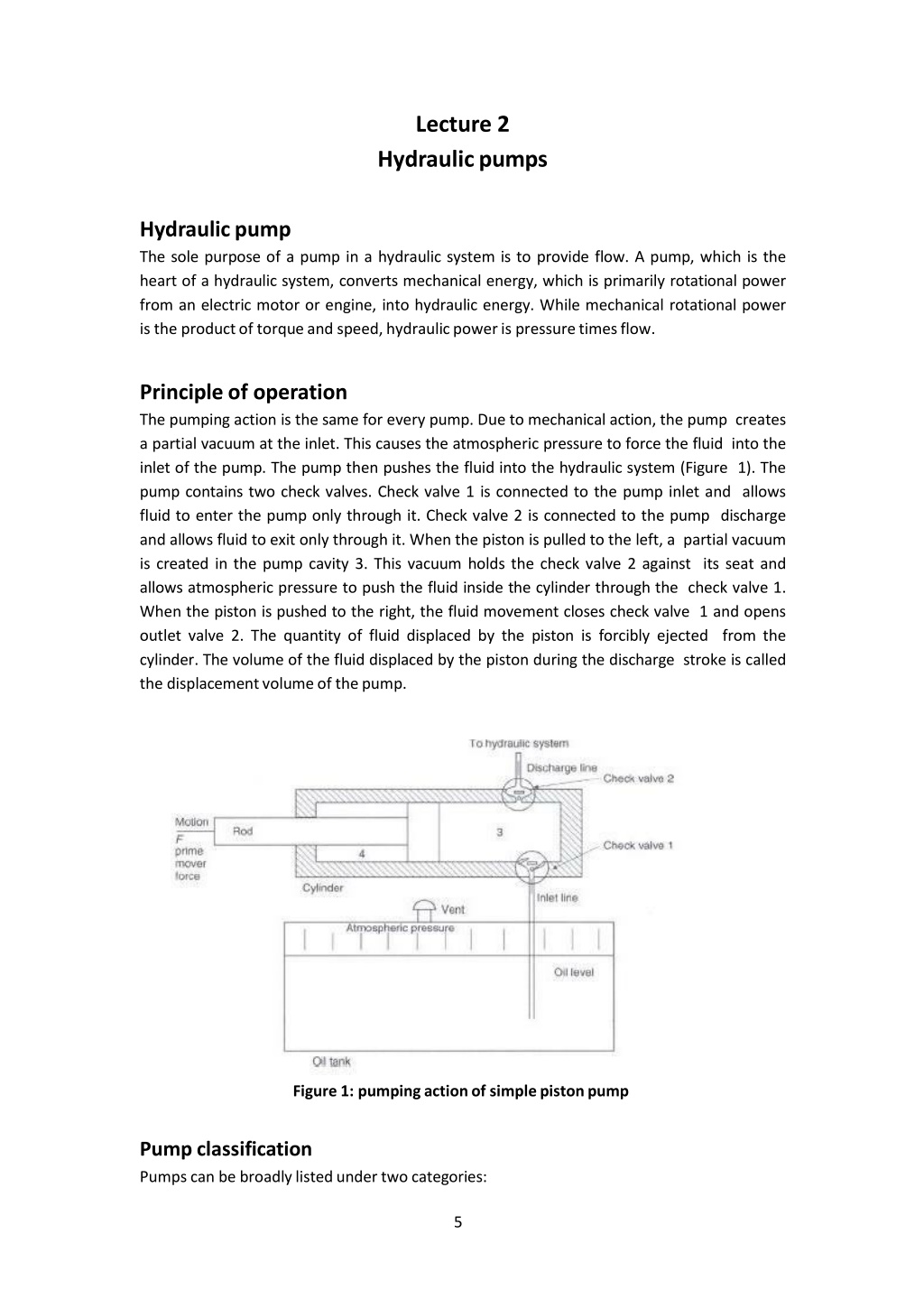
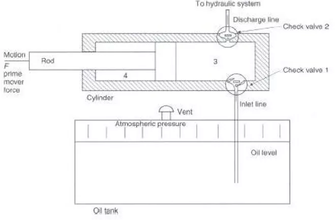
The pumping
action is the
same for
every
pump.
Due to
mechanical action,
the
pump
creates
a partial
vacuum
at the inlet.
This causes the
atmospheric
pressure to force
the
fluid
into the
inlet
of the
pump. The pump
then
pushes
the
fluid
into the
hydraulic system (Figure 1). The
pump contains two check valves. Check valve
1 is
connected to
the pump inlet and allows
fluid to enter
the
pump only through
it.
Check valve
2 is
connected
to the
pump discharge
and
allows fluid to
exit only
through
it. When the
piston
is
pulled to
the left, a partial
vacuum
is
created
in
the
pump cavity
3.
This vacuum
holds the
check valve
2
against
its
seat
and
allows atmospheric pressure
to
push the fluid inside the cylinder
through
the
check
valve
1.
When the
piston
is
pushed
to
the right,
the
fluid
movement
closes check valve
1 and opens
outlet
valve 2. The quantity
of
fluid displaced by
the
piston
is
forcibly
ejected
from
the
cylinder. The volume
of the
fluid displaced by
the piston
during
the
discharge stroke
is called
the
displacement volume
of
the
pump.
Figure 1:
pumping action of simple piston
pump
Pump
classification
Pumps can
be broadly listed under two
categories:
5

1.
Non-positive displacement pumps
and
2.
Positive displacement
pumps.
A.
Non-Positive Displacement
Pumps
These pumps are also known
as
hydro-dynamic pumps.
In
these pumps the fluid
is
pressurized by the rotation
of
the propeller and the fluid pressure
is
proportional
to
the
rotor speed. These pumps
can
not withstanding
high
pressures and
generally
used for
low-pressure and high-volume flow applications. The important advantages
of
non-
positive displacement
pumps
are lower initial cost, less operating maintenance because
of
less moving parts, simplicity
of
operation, higher reliability and suitability
with
wide
range
of
fluid
etc.
These pumps are primarily used for transporting fluids and find little
use
in
the hydraulic
or
fluid power industries. Centrifugal pump
is
the common
example
of
non-positive displacement
pumps.
B.
Positive displacement
pump
These
pumps
deliver
a
constant
volume
of
fluid
in
a
cycle.
The
discharge
quantity
per
revolution
is
fixed
in
these pumps and they produce fluid flow proportional
to
their
displacement and rotor speed. These pumps are used
in most of
the industrial fluid
power applications. The output fluid flow
is
constant and
is
independent
of
the system
pressure (load). The
important
advantage associated
with
these pumps
is
that the
high-
pressure and low-pressure areas (means
input
and output region) are separated and
hence the fluid cannot
leak
back
due
to
higher pressure
at
the outlets. These features
make the positive displacement pump most suited and universally accepted for hydraulic
systems. The important advantages
of
positive displacement
pumps
over
non-
positive
displacement
pumps
include capability
to
generate high pressures, high volumetric
efficiency, high power
to
weight ratio, change
in
efficiency throughout the pressure
range
is small
and wider operating range pressure and
speed.
Pump
Positive
displacement
Non-positive
displacement
Centrifugal
A
x
i
a
l
R
adi
a
l
R
ot
a
ry
Reciprocating
G
ear
Vane
Screw
Gear
Pumps
Gear
pump
is a
robust and
simple
positive displacement pump.
It
has two meshed gears
revolving about their respective axes. These gears
are
the only moving parts
in
the
pump. They are compact, relatively inexpensive and have few moving parts.
The
rigid


6
7
design
of
the gears and houses allow for very high pressures and the ability
to
pump
highly viscous fluids. They are suitable for
a
wide
range
of
fluids and offer self-priming
performance. Sometimes
gear
pumps are designed
to
function
as
either
a
motor
or a
pump.
These
pump includes helical
and
herringbone
gear
sets (instead
of
spur gears),
lobe shaped
rotors
similar
to
Roots blowers (commonly used
as
superchargers),
and
mechanical designs that allow the stacking
of
pumps.
Based
upon the design, the
gear
pumps are classified
as:
•
External
gear
pumps
•
Lobe
pumps
•
Internal
gear
pumps
•
Gerotor
pumps
Generally
gear
pumps are used
to
pump:
•
Petrochemicals: Pure
or
filled bitumen, pitch, diesel
oil,
crude
oil,
lube
oil
etc.
•
Chemicals: Sodium silicate, acids, plastics, mixed chemicals, isocyanates
etc.
•
Paint
and
ink
•
Resins and
adhesives
•
Pulp and paper: acid, soap, lye, black liquor, kaolin,
lime,
latex, sludge
etc.
•
Food: Chocolate, cacao butter, fillers, sugar, vegetable fats and oils,
molasses,
animal
food
etc.
1.
External gear
pump
A
schematic
of an
external
gear
pump
is
shown
in
Figure
2.
An
external
gear
pump consists
of
two gears usually equal
in
size,
which mesh
externally
and
are
housed
in
a
pump
case.
Each
gear
is
mounted
on
a
shaft,
which
is
supported
by
needle
bearings
in the
case covers. One
of these
shafts
is
coupled to
a
prime mover
and is
called the
drive
shaft.
The
gear
mounted
on
this
shaft
is
called
the
drive
gear.
It
drives
the
second
gear
as it
rotates. Two side plates
are provided one on
each side
of the
gear. The
side
plates
are
held
between
the gear
case
and case covers.
The rotating
gear
carries the fluid from the
tank
to
the
outlet
pipe.
The
suction
side
is
towards
the
portion
whereas
the
gear
teeth
come out
of
the mesh.
When
the gears rotate, volume
of
the chamber expands leading
to
pressure drop below atmospheric value. Therefore the vacuum
is
created and
the
fluid
is
pushed into the
void
due
to
atmospheric pressure. The fluid
is
trapped between
housing
and
rotating
teeth
of
the
gears.
The
discharge
side
of
pump
is
towards
the
portion where the
gear teeth
run
into the
mesh
and the volume decreases
between
meshing
teeth.
The
pump
has
a
positive internal
seal
against leakage; therefore, the fluid
is
forced into the outlet port. The
gear
pumps are often equipped with the side
wear
plate
to
avoid the
leakage.
The clearance between gear
teeth
and housing and between
side plate and
gear
face
is
very important and plays
an
important role
in
preventing
leakage. In
general, the
gap
distance
is
less than
10
micrometers. The amount
of
fluid
discharge
is
determined by the number
of gear teeth,
the volume
of
fluid between
each
pair of
teeth
and the speed
of
rotation. The important drawback
of
external
gear
pump
is
the
unbalanced
side
load
on
its
bearings.
It
is
caused
due
to
high
pressure
at
the outlet
and
low
pressure
at
the inlet which results
in
slower speeds and
lower
pressure ratings
in
addition
to
reducing the bearing life.
Gear pumps
are most
commonly used
for
the hydraulic fluid
power
applications and are widely used
in
chemical
installations
to
pump fluid
with a certain
viscosity.
Figure2: Gear pump
2. Lobe
Pump
Lobe pumps work
on
the similar principle
of
working
as
that
of
external gear pumps.
However
in
Lobe pumps, the lobes
do
not make any contact
like
external
gear
pump (see
Figure
3). Lobe contact
is
prevented by
external timing
gears
located in
the gearbox.
Similar
to
the external gear pump, the lobes rotate
to
create expanding volume
at
the
inlet.
Now,
the fluid flows into the
cavity
and
is
trapped by the
lobes.
Fluid travels
around the
interior of
casing
in
the pockets between the lobes and the casing. Finally,
the meshing
of
the lobes forces liquid
to
pass through the outlet port. The bearings are
placed out
of
the pumped liquid. Therefore the pressure
is limited
by
the
bearing
location
and shaft
deflection.
Figure 3: lope
pump
Lobe pumps are frequently used
in
food applications because they handle solids without
damaging the product. Large
sized
particles can be pumped much effectively than
in
other
positive
displacement
types.
As
the
lobes
do
not
make
any
direct
contact
8
9
therefore, the clearance
is
not
as
close
as in
other Positive displacement pumps. This
specific design
of
pump makes
it
suitable
to
handle
low
viscosity fluids
with
diminished
performance.
3. Internal Gear
Pump
Internal
gear
pumps are
exceptionally
versatile.
They
are often used for low or medium
viscosity fluids such
as
solvents and fuel
oil and
wide range
of
temperature. This
is non-
pulsing, self-priming and
can
run
dry for short periods.
It is a
variation
of
the basic
gear
pump.
It
comprises
of
an
internal
gear,
a
regular
spur
gear,
a
crescent-shaped
seal
and
an
external housing. The schematic
of
internal
gear
pump
is
shown
in
figure
4.
Liquid
enters
the suction port between the rotor (large exterior gear) and idler
(small
interior gear)
teeth.
Liquid travels through the pump between the
teeth
and crescent. Crescent divides
the liquid
and acts as a
seal between the suction and discharge ports. When
the
teeth
mesh on
the side opposite
to
the crescent
seal,
the fluid
is
forced out through the
discharge port
of
the pump. This clearance between gears
can
be adjusted
to
accommodate high temperature,
to
handle high
viscosity
fluids and
to
accommodate the
wear. These pumps are bi-rotational
so
that they
can
be used
to
load and unload the
vessels. As these pumps have only
two
moving parts and one stuffing box, therefore they
are reliable, simple
to
operate and
easy to
maintain. However, these
pumps
are not
suitable for high speed
and
high pressure applications. Only one bearing
is
used
in
the
pump therefore overhung
load on
shaft bearing reduces the life
of
the
bearing.
Applications
Some common internal
gear
pump applications
are:
•
All
varieties
of
fuel
oil
and
lube
oil
•
Resins and
Polymers
•
Alcohols and
solvents
•
Asphalt, Bitumen,
and
Tar
•
Polyurethane foam (Isocyanate and
polyol)
•
Food products such
as
corn
syrup,
chocolate, and peanut
butter
•
Paint, inks, and
pigments
•
Soaps and
surfactants
•
Glycol
Figure 4:
Internal gear
pump
4.
Gerotor
Pump
Gerotor
is
a
positive displacement pump. The name Gerotor
is
derived from "Generated
Rotor".
At
the most
basic
level,
a Gerotor is
essentially one that
is
moved via fluid power.
Originally this fluid
was
water,
today
the wider use
is in
hydraulic devices. The schematic
of Gerotor
pump
is
shown
in
figure
5. Gerotor
pump
is
an
internal
gear
pump without
the crescent.
It
consists
of
two rotors viz.
inner
and outer rotor. The inner rotor has
N
teeth,
and the outer rotor has
N+1
teeth. The inner rotor
is
located
off-center
and both
rotors rotate. The geometry
of
the
two
rotors partitions the volume between them into
N
different dynamically-changing volumes.
During
the rotation, volume
of each
partition
changes continuously. Therefore, any given volume first increases, and then decreases.
An
increase
in
volume creates vacuum. This
vacuum
creates suction, and thus, this part
of
the cycle sucks the fluid.
As
the volume decreases, compression occurs. During this
compression period, fluids
can
be pumped,
or
compressed (if they are gaseous
fluids).
The important advantages
of
the pumps are high speed operation, constant discharge
in
all
pressure conditions, bidirectional operation, less sound
in
running
condition and less
maintenance
due
to
only
two
moving parts and one stuffing box
etc.
However, the pump
is
having
some
limitations such
as
medium pressure operating range, clearance
is
fixed,
solids can’t be pumped and overhung
load on
the shaft bearing
etc.
Figure 5:
Gerotor
pump
Crescent
10
11
Applications
Gerotors
are widely used
in
industries and are produced
in
variety
of
shapes and
sizes
by
a
number
of
different methods.
These
pumps are primarily
suitable
for low pressure
applications such
as
lubrication systems
or
hot
oil
filtration systems,
but
can
also be
found
in low to
moderate pressure hydraulic
applications.
However common
applications are
as
follows:
•
Light fuel
oils
•
Lube
oil
•
Cooking oils
•
Hydraulic
fluid
Hydraulic pumps are essential components in hydraulic systems, converting mechanical energy into hydraulic energy to provide flow. There are two main categories of pumps - non-positive displacement pumps and positive displacement pumps. Non-positive displacement pumps, such as centrifugal pumps, work based on fluid pressurization by propeller rotation, while positive displacement pumps deliver a constant volume of fluid per cycle. Positive displacement pumps, like gear pumps, offer advantages such as high pressure capability, efficiency, and reliability, making them widely used in industrial fluid power applications.

Download Presentation

Please find below an Image/Link to download the presentation.
The content on the website is provided AS IS for your information and personal use only. It may not be sold, licensed, or shared on other websites without obtaining consent from the author.If you encounter any issues during the download, it is possible that the publisher has removed the file from their server.
You are allowed to download the files provided on this website for personal or commercial use, subject to the condition that they are used lawfully. All files are the property of their respective owners.
The content on the website is provided AS IS for your information and personal use only. It may not be sold, licensed, or shared on other websites without obtaining consent from the author.
E N D
Presentation Transcript
Lecture 2 Hydraulicpumps Hydraulic pump The sole purpose of a pump in a hydraulic system is to provide flow. A pump, which is the heart of a hydraulic system, converts mechanical energy, which is primarily rotational power from an electric motor or engine, into hydraulic energy. While mechanical rotational power is the productof torqueand speed,hydraulicpoweris pressuretimesflow. Principle of operation The pumping action is the same for every pump. Due to mechanical action, the pump creates a partial vacuum at the inlet. This causes the atmospheric pressure to force the fluid into the inlet of the pump. The pump then pushes the fluid into the hydraulic system (Figure 1). The pump contains two check valves. Check valve 1 is connected to the pump inlet and allows fluid to enter the pump only through it. Check valve 2 is connected to the pump discharge and allows fluid to exit only through it. When the piston is pulled to the left, a partial vacuum is created in the pump cavity 3. This vacuum holds the check valve 2 against its seat and allows atmospheric pressure to push the fluid inside the cylinder through the check valve 1. When the piston is pushed to the right, the fluid movement closes check valve 1 and opens outlet valve 2. The quantity of fluid displaced by the piston is forcibly ejected from the cylinder. The volume of the fluid displaced by the piston during the discharge stroke is called the displacementvolumeof thepump. Figure 1: pumping action of simple pistonpump Pumpclassification Pumps can be broadly listed under twocategories: 5
1. Non-positive displacement pumpsand 2. Positive displacementpumps. A. Non-Positive DisplacementPumps These pumps are also known as hydro-dynamic pumps. In these pumps the fluid is pressurized by the rotation of the propeller and the fluid pressure is proportional to the rotor speed. These pumps can not withstanding high pressures and generally used for low-pressure and high-volume flow applications. The important advantages of non- positive displacement pumps are lower initial cost, less operating maintenance because of less moving parts, simplicity of operation, higher reliability and suitability with wide range of fluid etc. These pumps are primarily used for transporting fluids and find little use in the hydraulic or fluid power industries. Centrifugal pump is the common example of non-positivedisplacementpumps. B. Positive displacementpump These pumps deliver a constant volume of fluid in a cycle. The discharge quantity per revolution is fixed in these pumps and they produce fluid flow proportional to their displacement and rotor speed. These pumps are used in most of the industrial fluid power applications. The output fluid flow is constant and is independent of the system pressure (load). The important advantage associated with these pumps is that the high- pressure and low-pressure areas (means input and output region) are separated and hence the fluid cannot leak back due to higher pressure at the outlets. These features make the positive displacement pump most suited and universally accepted for hydraulic systems. The important advantages of positive displacement pumps over non- positive displacement pumps include capability to generate high pressures, high efficiency, high power to weight ratio, change in efficiency throughout the pressure rangeis small and wideroperatingrangepressureand speed. volumetric Pump Positive displacement Non-positive displacement Centrifugal Axial Radial Rotary Reciprocating Gear Vane Screw GearPumps Gear pump is a robust and simple positive displacement pump. It has two meshed gears revolving about their respective axes. These gears are the only moving parts in the pump. They are compact, relatively inexpensive and have few moving parts. The rigid 6
design of the gears and houses allow for very high pressures and the ability to pump highly viscous fluids. They are suitable for a wide range of fluids and offer self-priming performance. Sometimes gear pumps are designed to function as either a motor or a pump. These pump includes helical and herringbone gear sets (instead of spur gears), lobe shaped rotors similar to Roots blowers (commonly used as superchargers), and mechanical designs that allow the stacking of pumps. Based upon the design, the gear pumps are classified as: External gear pumps Lobe pumps Internal gear pumps Gerotorpumps Generally gear pumps are used to pump: Petrochemicals: Pure or filled bitumen, pitch, diesel oil, crude oil, lube oil etc. Chemicals: Sodium silicate, acids, plastics, mixed chemicals, isocyanates etc. Paint and ink Resins and adhesives Pulp and paper: acid, soap, lye, black liquor, kaolin, lime, latex, sludge etc. Food: Chocolate, cacao butter, fillers, sugar, vegetable fats and oils, molasses, animal food etc. 1. External gear pump A schematic of an external gear pump is shown in Figure2. An external gear pump consists of two gears usually equal in size, which mesh externally and are housed in a pump case. Each gear is mounted on a shaft, which is supported by needle bearings in the case covers. One of these shafts is coupled to a prime mover and is called the drive shaft. The gear mounted on this shaft is called the drive gear. It drives the second gear as it rotates. Two side plates are provided one on each side of the gear. The side plates are held between the gear case and case covers. The rotating gear carries the fluid from the tank to the outlet pipe. The suction side is towards the portion whereas the gear teeth come out of the mesh. When the gears rotate, volume of the chamber expands leading to pressure drop below atmospheric value. Therefore the vacuum is created andthe fluid is pushed into the void due to atmospheric pressure. The fluid is trapped between housing and rotating teeth of the gears. The discharge side of pump is towards the portion where the gear teeth run into the mesh and the volume decreases between meshing teeth. The pump has a positive internal seal against leakage; therefore, the fluid is forced into the outlet port. The gear pumps are often equipped with the side wear plate to avoid the leakage. The clearance between gear teeth and housing and between side plate and gear face is very important and plays an important role in preventing leakage. In general, the gap distance is less than 10 micrometers. The amount of fluid discharge is determined by the number of gear teeth, the volume of fluid between each pair of teeth and the speed of rotation. The important drawback of external gear pump is the unbalanced side load on its bearings. It is caused due to high 7
pressure at the outlet and low pressure at the inlet which results in slower speeds and lower pressure ratings in addition to reducing the bearing life. Gear pumps are most commonly used for the hydraulic fluid power applications and are widely used in chemical installationsto pumpfluidwith a certain viscosity. Figure2: Gear pump 2. Lobe Pump Lobe pumps work on the similar principle of working as that of external gear pumps. However in Lobe pumps, the lobes do not make any contact like external gear pump (see Figure 3). Lobe contact is prevented by external timing gears located in the gearbox. Similar to the external gear pump, the lobes rotate to create expanding volume at the inlet. Now, the fluid flows into the cavity and is trapped by the lobes. Fluid travels around the interior of casing in the pockets between the lobes and the casing. Finally, the meshing of the lobes forces liquid to pass through the outlet port. The bearings are placed out of the pumped liquid. Therefore the pressure is limited by the bearing location and shaftdeflection. Figure 3: lope pump Lobe pumps are frequently used in food applications because they handle solids without damaging the product. Large sized particles can be pumped much effectively than in other positive displacement types. As the lobes do not make any direct contact 8
therefore, the clearance is not as close as in other Positive displacement pumps. This specific design of pump makes it suitable to handle low viscosity fluids with diminished performance. 3. Internal Gear Pump Internal gear pumps are exceptionally versatile. They are often used for low or medium viscosity fluids such as solvents and fuel oil and wide range of temperature. This is non- pulsing, self-priming and can run dry for short periods. It is a variation of the basic gear pump. It comprises of an internal gear, a regular spur gear, a crescent-shaped seal and an external housing. The schematic of internal gear pump is shown in figure 4. Liquid enters the suction port between the rotor (large exterior gear) and idler (small interior gear) teeth. Liquid travels through the pump between the teeth and crescent. Crescent divides the liquid and acts as a seal between the suction and discharge ports. When the teeth mesh on the side opposite to the crescent seal, the fluid is forced out through the discharge port of the pump. This clearance between gears can be adjusted to accommodate high temperature, to handle high viscosity fluids and to accommodate the wear. These pumps are bi-rotational so that they can be used to load and unload the vessels. As these pumps have only two moving parts and one stuffing box, therefore they are reliable, simple to operate and easy to maintain. However, these pumps are not suitable for high speed and high pressure applications. Only one bearing is used in the pumpthereforeoverhungload on shaftbearingreducesthe life of the bearing. Applications Some commoninternalgear pumpapplicationsare: All varietiesof fuel oil and lube oil Resinsand Polymers Alcoholsand solvents Asphalt,Bitumen,and Tar Polyurethanefoam (Isocyanateand polyol) Food productssuchas corn syrup, chocolate,and peanut butter Paint,inks,and pigments Soapsand surfactants Glycol 9
Crescent Figure 4: Internal gearpump 4. GerotorPump Gerotor is a positive displacement pump. The name Gerotor is derived from "Generated Rotor". At the most basic level, a Gerotor is essentially one that is moved via fluid power. Originally this fluid was water, today the wider use is in hydraulic devices. The schematic of Gerotor pump is shown in figure 5. Gerotor pump is an internal gear pump without the crescent. It consists of two rotors viz. inner and outer rotor. The inner rotor has N teeth, and the outer rotor has N+1 teeth. The inner rotor is located off-center and both rotors rotate. The geometry of the two rotors partitions the volume between them into N different dynamically-changing volumes. During the rotation, volume of each partition changes continuously. Therefore, any given volume first increases, and then decreases. An increase in volume creates vacuum. This vacuum creates suction, and thus, this part of the cycle sucks the fluid. As the volume decreases, compression occurs. During this compressionperiod,fluids can be pumped,or compressed(if they are gaseousfluids). The important advantages of the pumps are high speed operation, constant discharge in all pressure conditions, bidirectional operation, less sound in running condition and less maintenance due to only two moving parts and one stuffing box etc. However, the pump is having some limitations such as medium pressure operating range, clearance is fixed, solidscan tbe pumpedand overhungload on the shaftbearing etc. Figure 5: Gerotorpump 10
Applications Gerotors are widely used in industries and are produced in variety of shapes and sizes by a number of different methods. These pumps are primarily suitable for low pressure applications such as lubrication systems or hot oil filtration systems, but can also be found in low to moderate pressure hydraulic applications. However common applications are as follows: Light fuel oils Lube oil Cooking oils Hydraulicfluid 11