Hydraulic Cylinder Lever Systems Discussion
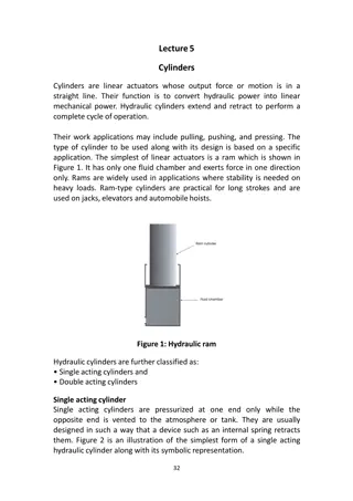
This section delves into the mechanics of cylinder loading in first-class, second-class, and third-class lever systems. Illustrations and explanations are provided for each lever type, highlighting how hydraulic cylinders transmit motion and power through lever mechanisms.

Download Presentation

Please find below an Image/Link to download the presentation.
The content on the website is provided AS IS for your information and personal use only. It may not be sold, licensed, or shared on other websites without obtaining consent from the author.If you encounter any issues during the download, it is possible that the publisher has removed the file from their server.
You are allowed to download the files provided on this website for personal or commercial use, subject to the condition that they are used lawfully. All files are the property of their respective owners.
The content on the website is provided AS IS for your information and personal use only. It may not be sold, licensed, or shared on other websites without obtaining consent from the author.
E N D
Presentation Transcript
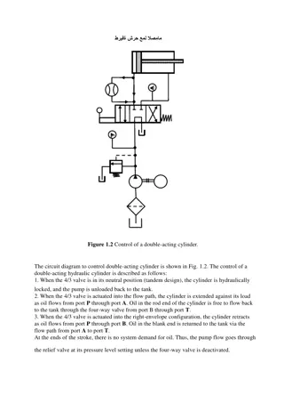
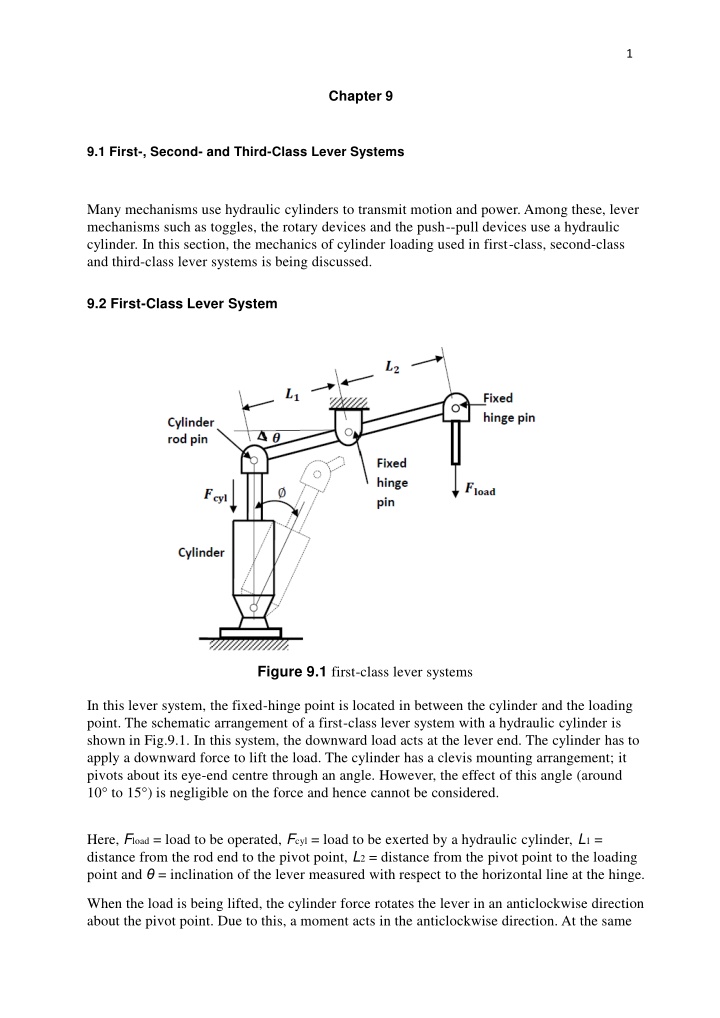
1 Chapter 9 9.1 First-, Second- and Third-Class Lever Systems Many mechanisms use hydraulic cylinders to transmit motion and power. Among these, lever mechanisms such as toggles, the rotary devices and the push--pull devices use a hydraulic cylinder. In this section, the mechanics of cylinder loading used in first-class, second-class and third-class lever systems is being discussed. 9.2 First-Class Lever System Figure 9.1 first-class lever systems In this lever system, the fixed-hinge point is located in between the cylinder and the loading point. The schematic arrangement of a first-class lever system with a hydraulic cylinder is shown in Fig.9.1. In this system, the downward load acts at the lever end. The cylinder has to apply a downward force to lift the load. The cylinder has a clevis mounting arrangement; it pivots about its eye-end centre through an angle. However, the effect of this angle (around 10 to 15 ) is negligible on the force and hence cannot be considered. Here, Fload = load to be operated, Fcyl = load to be exerted by a hydraulic cylinder, L1 = distance from the rod end to the pivot point, L2 = distance from the pivot point to the loading point and = inclination of the lever measured with respect to the horizontal line at the hinge. When the load is being lifted, the cylinder force rotates the lever in an anticlockwise direction about the pivot point. Due to this, a moment acts in the anticlockwise direction. At the same
2 9.3 Second-Class Lever System In this lever system, the loading point is in between the cylinder and the hinge point as shown in Fig.9.2. Figure 9.2 Second-class lever system
3 Note 3: Compared to the first-class lever, the second-class lever requires smaller cylinder force to drive the given load force for same L1 and L2 and load force. In other words, if we use a second-class lever cylinder, a smaller size cylinder can be used. Note 4: Compared to the first-class lever, the second-class lever also results in a smaller load stroke for a given cylinder stroke. 9.4 Third-Class Lever System For a third-class lever system shown in Fig. 9.4, the cylinder rod pin lies between the load road pin and the fixed-hinge pin of the lever. Figure 9.4 Third-class lever Note 4: In a third-class lever system, cylinder force is greater than load force.
4 Note 5: In a third-class lever system, load stroke is greater than the cylinder stroke and therefore requires a larger cylinder. Example 9.1
5 Example 9.2 For the system given in Fig.9.5 determine the force required to drive a 1000 N load. Figure 9.5 Solution: As seen, it is a first-class lever system. Taking moments about the hinge, we get Example 9.3 For the crane system, determine the hydraulic cylinder force required to lift a 2000 N load (Figs. 9.6 and 9.7). Figure 9.6
6 Figure 9.7 Example 9.4 Figure 9.8 shows a toggle mechanism. Find the output load force for a hydraulic cylinder force of 1000 N. Figure 9.8