CASE IH 6 Cylinder 6.7L NEF Tier 3 Engine (For Magnum 180, 190 and 210 Tractors) Service Repair Manual Instant Download (Part Number 84202702)
CASE IH 6 Cylinder 6.7L NEF Tier 3 Engine (For Magnum 180, 190 and 210 Tractors) Service Repair Manual Instant Download (Part Number 84202702)

Uploaded on | 0 Views
Download Presentation

Please find below an Image/Link to download the presentation.
The content on the website is provided AS IS for your information and personal use only. It may not be sold, licensed, or shared on other websites without obtaining consent from the author. Download presentation by click this link. If you encounter any issues during the download, it is possible that the publisher has removed the file from their server.
E N D
Presentation Transcript
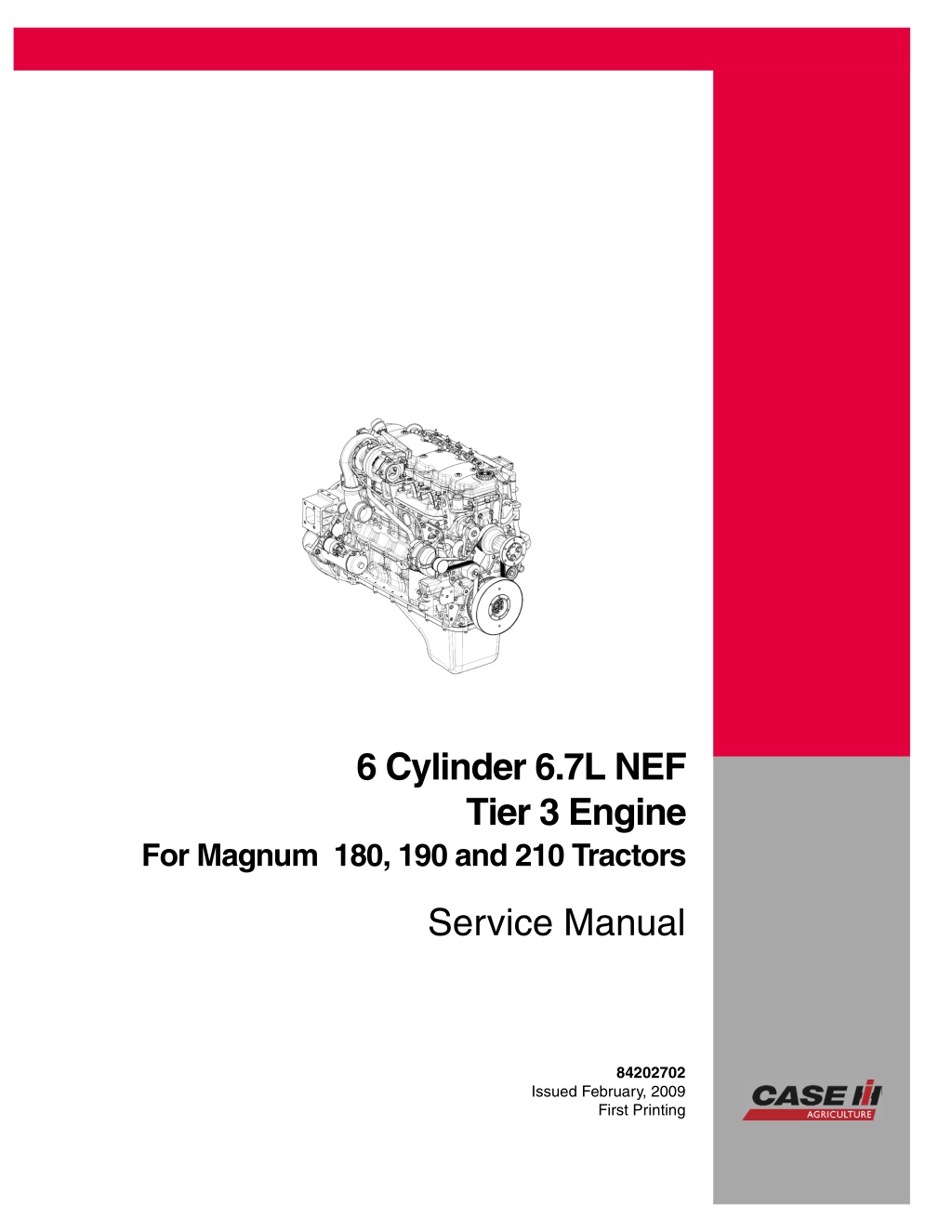
6 Cylinder 6.7L NEF Tier 3 Engine For Magnum 180, 190 and 210 Tractors Service Manual 84202702 Issued February, 2009 First Printing CNH America LLC 700 State Street Racine, WI. 53404 U.S.A. Printed in U.S.A. 2009 CNH America LLC. All Rights Reserved. Case IH is a registered trademark of CNH America LLC.
3 NEF TIER 3 ENGINES PRELIMINARY REMARKS Manuals for repairs are split into Parts and Sections, each one of which is marked by a numeral; the contents of these sections are indicated in the general table of contents. The sections dealing with things mechanic introduce the specifications, tightening torque values, tool lists, assembly detaching/reattaching operations, bench overhauling operations, diagnosis procedures and maintenance schedules. The sections (or parts) of the electric/electronic system include the descriptions of the electric network and the assembly s electronic systems, wiring diagrams, electric features of components, component coding and the diagnosis procedures for the control units peculiar to the electric system. The manual uses proper symbols in its descriptions; the purpose of these symbols is to classify contained information. In particular, there have been defined a set of symbols to classify warnings and a set for assistance operations. SYMBOLS - WARNINGS Danger for persons Missing or incomplete observance of these prescriptions can cause serious danger for persons safety. Danger of serious damage for the assembly Failure to comply, both fully or in part, with such prescriptions will involve serious damage to the assembly and may sometimes cause the warranty to become null and void. General danger It includes the dangers of above described signals. ! Environment protection Moreover, it describes the correct actions to be taken to ensure that the assembly isused insuch away soas toprotect the environment as much as possible. NOTE It indicates an additional explanation for a piece of information. Print P2D32N003 E Base - December 2006
4 NEF TIER 3 ENGINES GENERAL WARNINGS Warningsshowncannotberepresentativeofalldangersituationspossiblyoccurring.Therefore,itissuggestedtocontact immediate superiors where a danger situation occurs which is not described. ! Use both specific and general-purpose toolings according to the prescriptions contained in respective use and maintenance handbooks. Check use state and suitability of tools not subjected to regular check. The manual handling of loads must be assessed in advance because it also depends, besides weight, on its size and on the path. Handling by mechanical means must be with hoisters proper as for weight as well as for shape and volume. Hoisters, ropes and hooks used must contain clear indications on maximum carrying capacity acceptable. The use of said means is compulsorily permitted to authorised personnel only. Stay duly clear of the load, and, anyhow, never under it. In disassembling operations, always observe provided prescriptions; prevent mechanical parts being taken out from accidentally striking workshop personnel. Workshop jobs performed in pairs must always be performed in maximum safety; avoid operations which could be dangerous for the co-operator because of lack of visibility or of his/her not correct position. Keep personnel not authorised to operations clear of working area. You shall get familiar with the operatingand safety instructions for the assembly prior to operating on the latter. Strictly follow all the safety indications found on the assembly. Do not leave the running assembly unattended when making repairs. When carryingout workon the assembly lifted off the ground, verifythat theassembly isfirmly placedon itssupporting stands, and that the manual/automatic safety devices have been actuated in the event that the assembly is to be lifted by means of a hoist. When you have to operate on assemblies powered by natural gas, follow the instructions contained in the document, as well as all the specific safety standards provided for. Only remove radiator cap when the engine is cold by cautiously unscrewing it in order to let system residual pressure out. Inflammablefuelandallinflammablefluidsandliquidsmustbehandledwithcare,accordingtowhatcontainedonharmful materials 12-point cards. Refuelling must be performed outdoors with the engine off, avoiding lit cigarettes, free flames orsparksinordertopreventsuddenfires/bursts.Adequatelystoreinflammable,corrosiveandpollutingfluidsandliquids according to what provided by regulations in force. Compulsorily avoid to use food containers to store harmful liquids. Avoid to drill or bore pressurised containers, and throw cloths impregnated with inflammable substances into suitable containers. Worn out, damaged or consumable parts must be replaced by IVECO Motors original spares. Duringworkshopactivity,alwayskeeptheworkplaceclean;timelyclearorcleanfloorsfromaccidentalliquidoroilspots. Electric sockets and electric equipment necessary to perform repair interventions must meet safety rules. Base - December 2006 Print P2D32N00 E
https://www.ebooklibonline.com Hello dear friend! Thank you very much for reading. Enter the link into your browser. The full manual is available for immediate download. https://www.ebooklibonline.com
5 NEF TIER 3 ENGINES GENERAL WARNINGS Put on, where required by the intervention, garments and protections provided in accident prevention rules; contact with moving parts can cause serious injuries. Use suitable, preferably tight-fitted garments, and avoid to use jewels, scarves, etc. Do not leave the engine in motion at workshop locations not provided with a pipe to scavenge exhaust gas outside. Avoid to breathe fumescomingfromheatingorfrom paintweldingbecausethey cancause damagesto health;operate outdoors or in suitably ventilated areas. Put on proper inspirator if paint powder is present. Avoid contact with hot water or steam coming from the engine, radiator and pipings because they could cause serious burns. Avoid direct contact with liquidsand fluidspresent in vehicle systems; where an accidental contact hasoccurred, refer to 12-point cards for provisions to make. Clean the assemblies and carefully verify that they are intact prior to overhauling. Tidy up detached or disassembled parts with their securing elements (screws, nuts, etc.) into special containers. Check for the integrity of the parts which prevent screws from being unscrewed: broken washers, dowels, clips, etc. Self-locking nuts with an insert made of nylon must always be replaced. Avoid contact of rubber parts with diesel oil, petrol or other not compatible substances. Before washing under pressure mechanical parts, protect electric connectors, and central units, if present. Tightening screws and nuts must always be according to prescriptions; IVECO Motors commercial and assistance network is available to give all clarifications necessary to perform repair interventions not provided in this document. Before welding: - Disconnectallelectroniccentralunits,takepowercableoffbatterypositiveterminal(connectittochassisbonding) and detach connectors. - Remove paint by using proper solvents or paint removers and clean relevant surfices with soap and water. - Await about 15 minutes before welding. - Equip with suitable fire resistant protectionsto protect hoses or other componentswhere fluidsor othermaterials flow which may catch fire easily on welding. Should the vehicle be subjected to temperatures exceeding 80 C (dryer ovens), disassemble drive electronic central units. The disposal of all liquids and fluids must be performed with full observance of specific rules in force. Print P2D32N003 E Base - December 2006
6 NEF TIER 3 ENGINES GENERAL WARNINGS ON THE ELECTRIC SYSTEM If an intervention has to be made on the electric/electronic system, disconnect batteries from the system; in this case, always disconnect, as a first one, the chassis bonding cable from batteries negative terminal. ! Before connecting the batteries to the system, make sure that the system is well isolated. Disconnect the external recharging apparatus from the public utility network before taking apparatus pins off battery terminals. Do not cause sparks to be generated in checking if the circuit is energised. Do not use a test lamp in checking circuit continuity, but only use proper control apparatuses. Make sure that the electronic devices wiring harnesses (length, lead type, location, strapping, connection to screening braiding, bonding, etc.) comply with IVECO Motors system and are carefully recovered after repair or maintenance interventions. Measurements in drive electronic central units, plugged connections and electric connections to components can only be made on proper testinglines with special plugs and plugbushes. Never use improper meanslike wires,screwdrivers, clipsandthelikeinordertoavoidthedangerofcausingashortcircuit,aswellasofdamagingpluggedconnections,which would later cause contact problems. Tostartuptheengine,donotusefastchargers.Startupmustonlybeperformedwitheitherseparatebatteriesorspecial truck. A wrong polarisation of supply voltage in drive electronic central units (for instance, a wrong polarisation of batteries) can cause them to be destroyed. Disconnect the batteries from the system during their recharging with an external apparatus. On connecting, only screw up connector (temperature sensors, pressure sensors etc.) nuts at prescribed tightening torque. Before disconnecting the junction connector from an electronic central unit, isolate the system. Do not directly supply electronic central units servo components at nominal vehicle voltage. Cables must be arranged such as to result to be parallel to reference plane, i.e. as close as possible to chassis/body structure. Once the intervention on the electric system has been completed, recover connectors and wiring harnesses according to original arrangement. NOTE Connectorspresentmustbeseenfromcableside.Connectorsviewscontainedinthemanualarerepresentativeofcable side. Base - December 2006 Print P2D32N00 E
7 NEF TIER 3 ENGINES Bonding and screening Negativeleadsconnectedto asystem bondedpoint mustbe bothas shortand possible and star -connected toeach other,trying then to have their centering tidily and properly made (Figure 1, re. M). Further, following warnings are to be compulsorily observed for electronic components: - Electronic central units must be connected to system bonding when they are provided with a metallic shell. - Electronic central units negative cables must be connected both to a system bonding point such as the dashboard opening bonding (avoiding serial or chain connections), and to battery negative terminal. - Analog bonding (sensors), although not connected to battery negative system/terminal bonding, must have optimal isolation. Consequently, particularly considered must be parasitic resistances in lugs: oxidising, clinching defects, etc. - Screened circuits braiding must only electrically contact the end towards the central unit entered by the signal (Figure 2). If junction connectors are present, unscreened section d, near them, must be as short as possible (Figure 2). - - Cables must be arranged such as to result to be parallel to reference plane, i.e. as close as possible to chassis/body structure. Figure 1 NEGATIVE CABLES STAR CONNECTION TO SYSTEM BONDING M 3. Figure 2 88039 4. SCREENING THROUGH METALLIC BRAIDING OF A CABLE TO AN ELECTRONIC COMPONENT C. CONNECTOR d. DISTANCE ! 0 Print P2D32N003 E Base - December 2006
8 NEF TIER 3 ENGINES OPTIONAL ELECTRICAL AND MECHANICAL PARTS INSTALLATIONS Assembliesshallbemodifiedandequippedwithadditions -andtheiraccessoriesshall befitted -in accordancewith theassembling directives issued by IVECO Motors. It is reminded that, especially about the electric system, several electric sockets are provided for as series (or optional) sockets in order to simplify and normalise the electrical intervention that is care of preparation personnel. It is absolutely forbidden to make modifications or connections to electric central units wiring harnesses; in particular, the data interconnection line between central units (CAN line) is to be considered inviolable. CONVERSIONS INTERNATIONAL SYSTEM AND MOST USED DERIVED QUANTITIES BETWEEN THE MAIN UNITS OF MEASUREMENT OF THE Power 1 kW 1 kW 1 metric HP = 1 metric HP = 1 HP 1 HP = = 1.36 metric HP 1.34 HP 0.736 kW 0.986 HP 0.746 kW 1.014 metric HP = = Torque 1 Nm 1 kgm = = 0.1019 kgm 9.81 Nm Revolutions per time unit 1 rad/s 1 rpm = = 1 rpm x 0.1046 1 rad/s x 9.5602 Pressure 1 bar 1 kg/cm2 1 bar 1.02 kg/cm2 0.981 bar 105Pa = = = Where accuracy is not particularly needed: - Nm unit is for the sake of simplicity converted into kgm according to ratio 10:1 1 kgm = 10 Nm; - bar unit is for the sake of simplicity converted into kg/cm2according to ratio 1:1 1 kg/cm2 = 1 bar. Temperature 0 C 1 C 32 F (1 x 1.8 + 32) F = = Base - December 2006 Print P2D32N00 E
1 NEF TIER 3 ENGINES NEF TIER 3 ENGINES Part 1 NEF F4HE engines Part 2 NEF F4CE engines Part 3 NEF F4DE engines Part 4 NEF F4GE engines Print P2D32N003 E Base - December 2006
2 NEF TIER 3 ENGINES Base - December 2006 Print P2D32N00 E
1 F4HE NEF ENGINES Part 1 F4HE NEF ENGINES Sezione 1 General specifications 2 Fuel 3 Duty - Industrial application 4 Overhaul and technical specifications 5 Tools Appendix Safety prescriptions PREFACE TO USER S GUIDELINE MANUAL Section 1 describes the NEF engine illustrating its features and working in general. Section 2 describes the type of fuel feed. Section3relatestothespecificdutyandisdividedinfoursepa- rate parts: 1. Mechanical part, related to the engine overhaul, limited to those components with different characteristics based on the relating specific duty. 2. Electrical part, concerning wiring harness, electrical and electronic equipment with different characteristics based on the relating specific duty. 3. Maintenance planning and specific overhaul. 4. Troubleshooting part dedicated to the operators who, beingentitledtoprovidetechnicalassistance,shallhavesimple anddirectinstructionstoidentifythecauseofthemajorincon- veniences. Sections4and5 illustratetheoverhauloperationsoftheengi- neoverhaulonstandandthenecessaryequipmenttoexecute such operations. The appendix reports general safety prescriptionsto be follo- wedbyalloperatorswhetherbeingin-chargeofinstallationor maintenance, in order to avoid serious injury. Print P2D32N003 E Base - December 2006
2 F4HE NEF ENGINES Base - December 2006 Print P2D32N00 E
3 F4HE NEF ENGINES SPECIAL REMARKS Diagrams and symbols have been widely used to give a clearer and more immediate illustration of the subject being dealt with, (see next page) instead of giving descriptions of some operations or procedures. Example 1 = housing for connecting rod small end bush 1 Tighten to torque Tighten to torque + angular value 2 2 = housing for connecting rod bearings Print P2D32N003 E Base - December 2006
4 F4HE NEF ENGINES SYMBOLS - ASSISTANCE OPERATIONS Removal Disconnection Intake Refitting Connection Exhaust Removal Disassembly Operation Fitting in place Assembly Compression ratio Tolerance Weight difference Tighten to torque Tighten to torque + angle value Rolling torque Press or caulk Rotation Regulation Adjustment Angle Angular value Visual inspection Fitting position check Preload Measurement Value to find Check Number of revolutions Equipment Temperature Surface for machining Machine finish Pressure bar Oversized Higher than . Maximum, peak Interference Strained assembly Undersized Less than . Minimum Thickness Clearance Lubrication Damp Grease Selection Classes Oversizing Temperature < 0 C Cold Winter Temperature > 0 C Hot Summer Sealant Adhesive Air bleeding Replacement Original spare parts Base - December 2006 Print P2D32N00 E
5 F4HE NEF ENGINES UPDATING Section Description Page Date of revision 2, 23, 24, 47 52 3 Duty-industrial application Revi - February 2007 4 Overhaul specifications and technical 22, 23, 29, 30, 37 Revi - February 2007 3 7 5 Tools Revi - February 2007 Print P2D32N003 E Base - December 2006 Revi - February 2007 Revi - February 2007
6 F4HE NEF ENGINES Base - December 2006 Print P2D32N00 E
1 F4AE NEF ENGINES SECTION 1 - GENERAL SPECIFICATIONS SECTION 1 General specifications Page CORRESPONDENCE BETWEEN TECHNICAL CODE AND COMMERCIAL CODE . . . . . . . . . . . . . 3 LUBRICATION . . . . . . . . . . . . . . . . . . . . . . . . . . 4 - 4-cylinder engine version . . . . . . . . . . . . . . . . . 4 - 6-cylinder engine version . . . . . . . . . . . . . . . . . 5 OIL VAPOUR RECYCLING . . . . . . . . . . . . . . . . 6 - Version with blow-by filter . . . . . . . . . . . . . . . . 6 - Version without blow-by filter . . . . . . . . . . . . . 7 COOLING SYSTEM . . . . . . . . . . . . . . . . . . . . . . 8 - 4-cylinder engine version . . . . . . . . . . . . . . . . . 8 - 6-cylinder engine version . . . . . . . . . . . . . . . . . 9 AIR INDUCTION - BOOST DIAGRAM . . . . . . . 10 - Description . . . . . . . . . . . . . . . . . . . . . . . . . . . 10 EXHAUST GAS RE-CIRCULATION SYSTEM (EGR) 11 Print P2D32N003 E Base - December 2006
2 SECTION 1 - GENERAL SPECIFICATIONS F4AE NEF ENGINES Base - December 2006 Print P2D32N00 E
Suggest: For more complete manuals. Please go to the home page. https://www.ebooklibonline.com If the above button click is invalid. Please download this document first, and then click the above link to download the complete manual. Thank you so much for reading
3 F4AE NEF ENGINES SECTION 1 - GENERAL SPECIFICATIONS CORRESPONDENCE BETWEEN TECHNICAL CODE AND COMMERCIAL CODE Technical Code Commercial Code F4HE9484A*J101 F4HE9684P*J101 F4HE9687B*J101 F4HE9687E*J101 F4HE9687X*J101 F4HE9684A*J100 F4HE9684Q*J100 F4HE9684W*J100 F4HE9687P*J100 F4HE9687A*J100 N45 ENT.X N67 ENT.X Print P2D32N003 E Base - December 2006
4 SECTION 1 - GENERAL SPECIFICATIONS F4AE NEF ENGINES Lubrication involves the heat exchanger as well, the turbo- blower and the eventual compressor for any eventual com- pressed air system. All these components may often vary ac- cording to the specific duty and will therefore be examined in the specific section. LUBRICATION Lubricationbyforcedcirculationisachievedthroughoilrotary expansion pump (1), placedin thefront partof thebasement, drivenbythestraight-toothgearsplinedtotheshaft sbarhold. From the pan, the lubrication oil flows to the driving shaft, to the camshaft and to the valve drive. 4-cylinder engine version Figure 1 (Demonstration) Oil recover from the turbo-blower To the exchanger and to the turbo-blower Routing of oil return by gravity to sump 108511 Routing of oil return by gravity to sump Introduction of oil LUBRICATION SYSTEM LAYOUT 4-cylinder engines Base - December 2006 Print P2D32N00 E
https://www.ebooklibonline.com Hello dear friend! Thank you very much for reading. Enter the link into your browser. The full manual is available for immediate download. https://www.ebooklibonline.com