Fracture Mechanics in Engineering Structures
Explore the world of fracture mechanics in engineering structures, encompassing the importance of stress fields, crack tip behaviors, fracture toughness, ductile versus brittle materials, and the influence of temperature dependence on material properties. Delve into the intricacies of crack initiation and propagation, stress intensity factors, and the critical values governing fracture occurrences in different materials. Gain insights into how these principles shape the design and analysis of engineering components to ensure structural integrity and safety.

Download Presentation

Please find below an Image/Link to download the presentation.
The content on the website is provided AS IS for your information and personal use only. It may not be sold, licensed, or shared on other websites without obtaining consent from the author.If you encounter any issues during the download, it is possible that the publisher has removed the file from their server.
You are allowed to download the files provided on this website for personal or commercial use, subject to the condition that they are used lawfully. All files are the property of their respective owners.
The content on the website is provided AS IS for your information and personal use only. It may not be sold, licensed, or shared on other websites without obtaining consent from the author.
E N D
Presentation Transcript
Fracture of Divertor Structures Jake Blanchard ARIES Meeting April 2011
Outline Primer on Fracture Mechanics Preliminary Results for Divertor Structures Future Plans
Design of Engineering Structures In early 20thcentury, design of metal structures was strictly stress based Onset of high performance ships (Liberty ships, WWII) changed things
What happened? high strength stress fracture Low strength Temperature
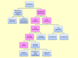
Fracture Mechanics Size and Orientation of Cracks Stress Fields Material Properties
Crack Tip Stress Fields (Elastic) Consider a sharp crack in an elastic material r K is stress intensity factor Function of geometry and loading Fracture occurs when K reaches critical value (KIC fracture toughness)
An Example Consider an infinite plate with a through crack K I = = a K IC K = IC allow a Glass: KIC=1 MPa-m0.5 Al: KIC=20 MPa-m0.5 For a=100 microns, fracture stresses are 56 MPa for glass and 1,100 MPa for Al
Fracture Toughness (room temp) Material 7075 Aluminum 4340 Steel Silicon Carbide Polystyrene Tungsten (polycrystalline) Beryllium Toughness (MPa m^0.5) 24 50 4 1 5 10 These values depend strongly on processing.
Stress Fields in Ductile Materials Ductile materials will develop plastic deformation at crack tips This toughens material and resists catastrophic crack growth Previous analysis is not valid Analysis uses integral around crack tip, rather than stress intensity factor
Failure Criterion for Ductile Materials Base failure prediction on work required to create fresh fracture surface Write as line integral u = J Wdx t ds W=strain energy density T=tractions U=displacement 2 I x 1 1 2 = 2 J K IC IC 3 E
Fatigue Crack Growth Previous analyses refer to catastrophic, unstable crack growth Repeated application of loads can lead to incremental crack growth
Characterizing Cracks Key Question: What is initial crack size? We need non-destructive examination (NDE) Options: Dye penetrant Ultrasound X-rays Eddy currents Thermography Etc. Costs and capabilities vary
ITER Structural Design Criteria Primary Loads . 0 33 K K I C Primary + Secondary Loads . 0 67 K K I C Elasto-Plastic Analysis . 0 67 J J I C
ANSYS Finite Element Model of Circumferential Crack Stress intensities along crack face using the ANSYS CINT command Elastic-Plastic material properties for Tungsten used Currently only pressure loads are considered, but thermal stresses to be included Crack face
Initial Fracture Studies Based on T -Tube Geometry and Pressure Loads Tungsten OD = 15 mm Coolant pressure ~ 10 Mpa Coolant inlet temperature ~ 600 oC t = 1 mm
Initial Studies Compute Stress Intensities for Axial Cracks in Pressurized Cylinder Case 1: Circular crack; c/a=1 Case 2: Elliptical crack; c/a=2 Use elastic-plastic properties for tungsten. Calculate J1 and then report equivalent KI.
Variation of Stress Intensity with Location along Crack Tip (a = 0.1 mm) 1.3 cylindrical 1.2 elliptical K1 (MPa-m1/2) 1.1 1 0.9 Case 1: Circular crack; c/a=1 0.8 0 15 30 45 60 75 90 Case 2: Elliptical crack; c/a=2 (degrees) a = 0.1mm
Maximum Stress Intensity as a Function of Crack Depth 3.5 3 2.5 K1 (MPa-m1/2) 2 1.5 Cylindrical 1 Elliptical 0.5 0 0 0.1 0.2 0.3 0.4 0.5 0.6 Crack Depth (mm)
Conclusions We ve got to include fracture in our design analysis, particularly when using materials with limited ductility So far, there are no major red flags We will include thermal stresses in the future


")

")