FPGA Centric Dataflow Buffer Management Overview


Erdem Motuk
Erdem Motuk
12 July 2018
12 July 2018
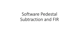
BUFFER MANAGEMENT
BUFFER MANAGEMENT
for FPGA Centric Dataflow
for FPGA Centric Dataflow
•
FPGA Centric Dataflow
FPGA Centric Dataflow
•
10 second buffer in DRAM (DDR4)
10 second buffer in DRAM (DDR4)
•
Solid state storage for longer period if SN trigger
Solid state storage for longer period if SN trigger
Diagram – Babak Abi
•
A
FIFO structure using the
external DDR4 RAM
•
The input is the compressed
detector data and the outputs
are:
•
Selected data as a
result of the trigger
command to the event
builder,
•
The detector data sent
to the SSD interface in
case of a SN trigger
•
The compressed data will come with the timestamps
•
These timestamps will be extracted and along with the
corresponding memory addresses will be stored in a table
(time stamp FIFO)
•
The data will be written to the DDR4 RAM (memory
addresses to the time stamp table)
•
With a trigger command the FIFO will be read out (or
readout will start after a certain period of time)
•
If the time stamp on the trigger command matches the time
stamp of the data read the data will be sent to the event
builder or SSD storage
Uncompressed data volume (per FPGA)
Uncompressed data volume (per FPGA)
12 bits x 2 MHz → 24 Mbit/s
12 bits x 2 MHz → 24 Mbit/s
5x128 channels → 15.36 Gbit/s
5x128 channels → 15.36 Gbit/s
10 seconds → 19.2 GBytes
10 seconds → 19.2 GBytes
Possible compression ratio 1 to 3
Possible compression ratio 1 to 3
Proposed hardware – DPM board
Proposed hardware – DPM board
Xilinx UtraScale+ xzcu15 FPGA
Xilinx UtraScale+ xzcu15 FPGA
16 GByte DDR4 RAM
16 GByte DDR4 RAM
8 GByte connected to the PL (programmable logic)
8 GByte connected to the PL (programmable logic)
part
part
8 GByte assigned to the PS (processing system)
8 GByte assigned to the PS (processing system)
part
part
Using the PL connected RAM as a FIFO
Using the PL connected RAM as a FIFO
Traditional DRAM access via MIG
Traditional DRAM access via MIG
Ultrascale / UC+ architecture has dedicated DDR4 PHYs
Ultrascale / UC+ architecture has dedicated DDR4 PHYs
Xilinx MIG IP with the Memory Controller soft core
Xilinx MIG IP with the Memory Controller soft core
Flexibility in the soft memory controller to improve latency
Flexibility in the soft memory controller to improve latency
Current Xilinx IP for using the DRAM as a FIFO - AXI
Current Xilinx IP for using the DRAM as a FIFO - AXI
Virtual FIFO Controller
Virtual FIFO Controller
•
Multiple AXI4-Stream FIFOs using an AXI4 slave memory
Multiple AXI4-Stream FIFOs using an AXI4 slave memory
controller (MIG+soft MC)
controller (MIG+soft MC)
•
Up to 8 channels
Up to 8 channels
Block Diagram for the Virtual FIFO controller
Block Diagram for the Virtual FIFO controller
•
The input side is AXI4-stream (32/64/.. data width) – This can
The input side is AXI4-stream (32/64/.. data width) – This can
be ok with a translation module – Compression output to AXI4S
be ok with a translation module – Compression output to AXI4S
packets
packets
•
E
E
a
a
c
c
h
h
c
c
h
h
a
a
n
n
n
n
e
e
l
l
c
c
a
a
n
n
b
b
e
e
u
u
p
p
t
t
o
o
2
2
5
5
6
6
M
M
b
b
y
y
t
t
e
e
s
s
i
i
z
z
e
e
–
–
N
N
o
o
t
t
g
g
o
o
o
o
d
d
f
f
o
o
r
r
o
o
u
u
r
r
p
p
u
u
r
r
p
p
o
o
s
s
e
e
Using Memory Controller IP along with a controller block
Using Memory Controller IP along with a controller block
•
Controller – accepts burst transactions from the user interface and
Controller – accepts burst transactions from the user interface and
generates transactions
generates transactions
•
Takes care of the SDRAM timing parameters and refresh
Takes care of the SDRAM timing parameters and refresh
•
Physical Layer – SERDES, delays, memory initialisation and
Physical Layer – SERDES, delays, memory initialisation and
calibration
calibration
Using Memory Controller IP along with a controller block
Using Memory Controller IP along with a controller block
•
Application Interface – provides a simple FIFO-like interface to the
Application Interface – provides a simple FIFO-like interface to the
user. Data is buffered and read data is presented in the request order
user. Data is buffered and read data is presented in the request order
•
Two choices for interfacing – User Interface and AXI4 slave interface
Two choices for interfacing – User Interface and AXI4 slave interface
•
User Interface – An address input (app_addr_width-1:0), a command
User Interface – An address input (app_addr_width-1:0), a command
input (2:0), a strobes for address, command and data and other
input (2:0), a strobes for address, command and data and other
control signals
control signals
•
The input and output data widths (app_data_width) are
The input and output data widths (app_data_width) are
2 x
2 x
nCK_PER_CLK (4) x DQ_WIDTH
nCK_PER_CLK (4) x DQ_WIDTH
(when ECC is disabled)
(when ECC is disabled)
•
AXI4 slave interface – Built on top of the user interface to provide
AXI4 slave interface – Built on top of the user interface to provide
AXI4 standard memory mapped interface
AXI4 standard memory mapped interface
•
Separate channels for read and write addresses
Separate channels for read and write addresses
•
Arbitration user selectable – Simple round robin, TDM, read/write
Arbitration user selectable – Simple round robin, TDM, read/write
priority etc.
priority etc.
•
Data width can be smaller than the
Data width can be smaller than the
APP_DATA_WIDTH
APP_DATA_WIDTH
Using Memory Controller IP along with a controller block
Using Memory Controller IP along with a controller block
•
Performance related parameters
Performance related parameters
•
MEM_ADDR_ORDER determines how the address input is mapped
MEM_ADDR_ORDER determines how the address input is mapped
to the SDRAM address bus and chip select pins
to the SDRAM address bus and chip select pins
•
ROW_COLUMN_BANK is the recommended setting – affects the bit
ROW_COLUMN_BANK is the recommended setting – affects the bit
fields in the address input
fields in the address input
•
Ideal for linear increments – As in the FIFO application
Ideal for linear increments – As in the FIFO application
•
C_S_AXI_DATA_WIDTH is the width of the data signals – better
C_S_AXI_DATA_WIDTH is the width of the data signals – better
performance when it’s equal to the APP_DATA_WIDTH - not the best
performance when it’s equal to the APP_DATA_WIDTH - not the best
for our application but short packet sizes are also possible with an
for our application but short packet sizes are also possible with an
upsizer block (instantiated within the core – selectable with a
upsizer block (instantiated within the core – selectable with a
parameter)
parameter)
Block Diagram for the Vivado design for the KCU105 board
Block Diagram for the Vivado design for the KCU105 board
Conclusion
Conclusion
Buffer management for the PL connected DDR4 memory can
Buffer management for the PL connected DDR4 memory can
use the memory controller IP from Xilinx
use the memory controller IP from Xilinx
AXI4 connection to the memory controller seems to be a good
AXI4 connection to the memory controller seems to be a good
choice
choice
KCU105 development board (Ultrascale) can be used for the
KCU105 development board (Ultrascale) can be used for the
development for the module (PL connected DDR4 architecture
development for the module (PL connected DDR4 architecture
is the same)
is the same)
Development can start very soon (with hypothetical inputs)
Development can start very soon (with hypothetical inputs)
If the RAM connected to the PS side needs to be used, a DMA
If the RAM connected to the PS side needs to be used, a DMA
scheme has to be devised (not all 8 GByte of RAM will be
scheme has to be devised (not all 8 GByte of RAM will be
available for buffering – operating system)
available for buffering – operating system)
A scheme using both the PL and the PS memory might be
A scheme using both the PL and the PS memory might be
possible – more complexity
possible – more complexity
This overview discusses buffer management for FPGA-centric dataflow systems, including the use of DDR4 RAM, solid-state storage, FIFO structures, and trigger commands for efficient data processing and storage. It also covers the handling of compressed and uncompressed data volumes, proposed hardware configurations, and utilizing PL-connected RAM as a FIFO. Various diagrams illustrate the concepts and processes involved in managing data within FPGA-centric architectures.

Download Presentation

Please find below an Image/Link to download the presentation.
The content on the website is provided AS IS for your information and personal use only. It may not be sold, licensed, or shared on other websites without obtaining consent from the author.If you encounter any issues during the download, it is possible that the publisher has removed the file from their server.
You are allowed to download the files provided on this website for personal or commercial use, subject to the condition that they are used lawfully. All files are the property of their respective owners.
The content on the website is provided AS IS for your information and personal use only. It may not be sold, licensed, or shared on other websites without obtaining consent from the author.
E N D
Presentation Transcript
BUFFER MANAGEMENT for FPGA Centric Dataflow Erdem Motuk 12 July 2018
FPGA Centric Dataflow 10 second buffer in DRAM (DDR4) Solid state storage for longer period if SN trigger Diagram Babak Abi 2
A FIFO structure using the external DDR4 RAM The input is the compressed detector data and the outputs are: Selected data as a result of the trigger command to the event builder, The detector data sent to the SSD interface in case of a SN trigger 3
The compressed data will come with the timestamps These timestamps will be extracted and along with the corresponding memory addresses will be stored in a table (time stamp FIFO) The data will be written to the DDR4 RAM (memory addresses to the time stamp table) With a trigger command the FIFO will be read out (or readout will start after a certain period of time) If the time stamp on the trigger command matches the time stamp of the data read the data will be sent to the event builder or SSD storage 4
Uncompressed data volume (per FPGA) 12 bits x 2 MHz 24 Mbit/s 5x128 channels 15.36 Gbit/s 10 seconds 19.2 GBytes Possible compression ratio 1 to 3 Proposed hardware DPM board Xilinx UtraScale+ xzcu15 FPGA 16 GByte DDR4 RAM 8 GByte connected to the PL (programmable logic) part 8 GByte assigned to the PS (processing system) part 5
Using the PL connected RAM as a FIFO Traditional DRAM access via MIG Ultrascale / UC+ architecture has dedicated DDR4 PHYs Xilinx MIG IP with the Memory Controller soft core Flexibility in the soft memory controller to improve latency Current Xilinx IP for using the DRAM as a FIFO - AXI Virtual FIFO Controller Multiple AXI4-Stream FIFOs using an AXI4 slave memory controller (MIG+soft MC) Up to 8 channels 6
Block Diagram for the Virtual FIFO controller The input side is AXI4-stream (32/64/.. data width) This can be ok with a translation module Compression output to AXI4S packets Each channel can be up to 256 Mbyte size Not good for our purpose 7
Using Memory Controller IP along with a controller block Controller accepts burst transactions from the user interface and generates transactions Takes care of the SDRAM timing parameters and refresh Physical Layer SERDES, delays, memory initialisation and calibration 8
Using Memory Controller IP along with a controller block Application Interface provides a simple FIFO-like interface to the user. Data is buffered and read data is presented in the request order Two choices for interfacing User Interface and AXI4 slave interface User Interface An address input (app_addr_width-1:0), a command input (2:0), a strobes for address, command and data and other control signals The input and output data widths (app_data_width) are 2 x nCK_PER_CLK (4) x DQ_WIDTH(when ECC is disabled) AXI4 slave interface Built on top of the user interface to provide AXI4 standard memory mapped interface Separate channels for read and write addresses Arbitration user selectable Simple round robin, TDM, read/write priority etc. Data width can be smaller than the APP_DATA_WIDTH 9
Using Memory Controller IP along with a controller block Performance related parameters MEM_ADDR_ORDER determines how the address input is mapped to the SDRAM address bus and chip select pins ROW_COLUMN_BANK is the recommended setting affects the bit fields in the address input Ideal for linear increments As in the FIFO application C_S_AXI_DATA_WIDTH is the width of the data signals better performance when it s equal to the APP_DATA_WIDTH - not the best for our application but short packet sizes are also possible with an upsizer block (instantiated within the core selectable with a parameter) 10
Conclusion Buffer management for the PL connected DDR4 memory can use the memory controller IP from Xilinx AXI4 connection to the memory controller seems to be a good choice KCU105 development board (Ultrascale) can be used for the development for the module (PL connected DDR4 architecture is the same) Development can start very soon (with hypothetical inputs) If the RAM connected to the PS side needs to be used, a DMA scheme has to be devised (not all 8 GByte of RAM will be available for buffering operating system) A scheme using both the PL and the PS memory might be possible more complexity 12


")