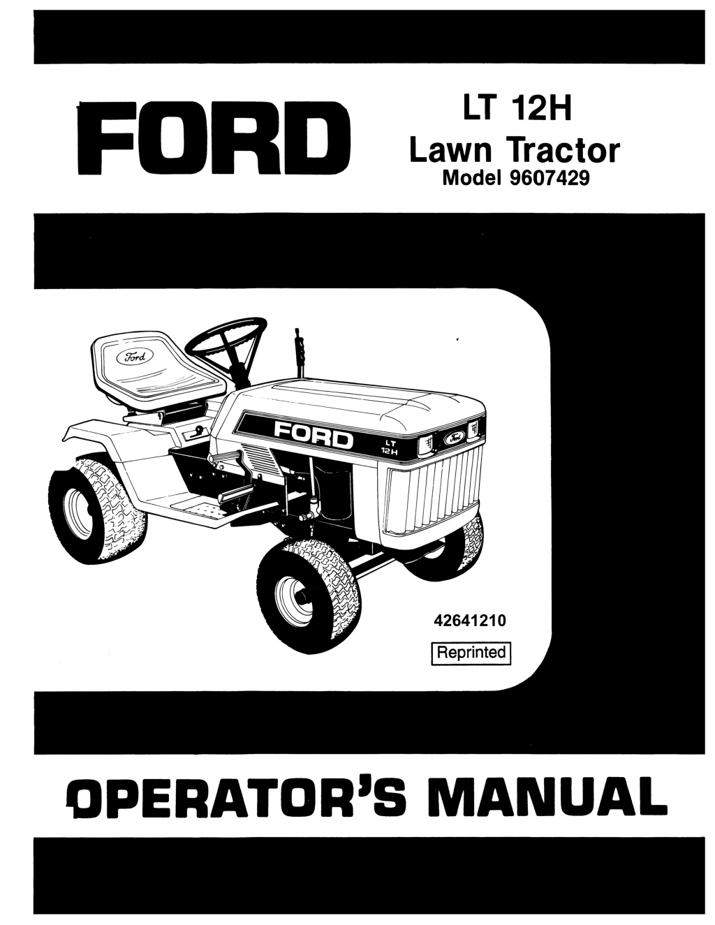
Ford LT12H Lawn Tractor Operator’s Manual Instant Download (Publication No.42641210)
Please open the website below to get the complete manualnn//
Download Presentation

Please find below an Image/Link to download the presentation.
The content on the website is provided AS IS for your information and personal use only. It may not be sold, licensed, or shared on other websites without obtaining consent from the author. Download presentation by click this link. If you encounter any issues during the download, it is possible that the publisher has removed the file from their server.
E N D
Presentation Transcript
INTRODUCTION NOnCE: A decal with the product model number and ~ number of your unit is on the left side of the tractor frdllll engine base assembly. Record these numbers in the spaCes provided below. Engine model. type and code numbers are located on the engine blo'N9f' housing. cylinder head shield or backplate. This operator's manual has been prepared to provide the information you need to correctly assemble. operate and maintain your unit. Read it carefully and keep it for Mure reference. Should you ever need repair parts or service. con- tact your authorized parts and service dealer. Be sure safety precautions are observed. Read and follow all safety and operating instructions in this operator's manual. . __________________________ __ ~ o d u c t M o d e I N o ~ o d u c t Serial No. Ally references made in this manual conceming the right- or left-hand sides are determined with the operator facing for- ward in the operating poSition. Engine Model No. Engine Type No. The replacement of any part on this product by other than the manufacturer's authorized replacement part may adversely affect the performance. durability or safety of this product. Engine Code No. Dealer Purchased From _______________ _ Date Purchased _____________________ __ The manufacturer reserves the right to make changes on. or add improvements to its product at any time without prior notice or obligation. The manufacturer also reserves the right to decide. upon its descretion and at any time. to discontinue a product. Dealer Address Dealer Telephone No. C1264
TABLE OF CONTENTS ......... Safety Precautions ........ ........ . ... 1 .1-1 .2 ,.tontrols And ~ p e r a t l o n Safety Interlock System ... ........ ... . ... 2.2 Brake Clutch Pedal . .. .. ... . ....... .. ... 2.2 Forward And Reverse Traction Drive Speed Control Pedals ... ..... ... ... 2.2 Ground Speed Control Lever .. ... .. . . ... 2.2 Engine Speed Control. ... ..... .......... 2.3 Manual P.T.o. (Power Take Off) Lever ..... 2.3 Headlight Switch .. .. . .. ..... . .. ........ 2.3 Ignition Switch ............. . .... . .. ..... 2.3 Seat Adjuster Handle ......... . . .. . ..... 2.3 Parking Brake Latch . .. ..... ............. 2.4 Attachment Lift Lever . .... ..... ......... 2.4 Tow Valve Lever ... . . .. .. .. .. ........... 2.4 Opening Hood . . ...... ....... .......... 2.4 3 Trial Run Seat Adjustment .... , ............. . ..... 3.1 4 Maintenance And Lubrication Break-In Maintenance And Lubrication ... 4.1 Daily Schedule ......... . ............... 4.1 25 Hour Schedule . .. . . ... . . ............. 4.2 100 Hour Schedule . ...... ....... .. .. 4.3-4.4 5 Adjustment And Servicing Primary Traction Belt .. ... ...... . . ..... .. 5.1 Belt Diagram ..................... .. . . . 5.2 Secondary Traction Belt ........ .... ... .. 5.3 Hydrostatic Drive .......... ... ......... . 5.3 Tow Valve Lever .... .. .... .............. 5.3 Brake Cable/Parking Brake ........ . ... . 5.4 Brake Pad ..................... ..... ... 5.4 Steering Gear .. ..... .......... .... . . ... 5.5 6 Electrical System Battery-Electrolyte Level ...... ... . . .... . 6.1 Cleaning The Battery . .. . . .. . .. ........ 6.1 Battery-Jump Starting ..... .. ... ....... . 6.1 Fuse .................... .. . .. . . .. ... . . . 6.1 Safety Interlock System ....... .. ...... .. 6.1 7 Storage .............. .......... ..... .. .. . 7.1 8 Trouble Shooting .... . .. . . . . . ...... .... . . . 8.1 9 Wiring Diagram .. . .. ... .. ... ..... . . '" .. . 9.1 10 Set-Up And Assembly Hardware Bag Contents .. .. ....... .. .. 10.1 Battery ... ... . ............ . .. ..... 10.2-10.3 Steering Wheel .......... .... ..... . ... 10.3 Seat ........ ....... .. .. . . .. .. ..... .. . 10.4 Initial Servicing .. .. ...... ...... .. .. .... 10.5 11 Replacement Decals Safety ........... . .... . ... .......... . . 11.1 Standard .. .. ......... . .. ... . . . . ... . .. 11.2 12 Optional Accessories ..... .. .. . ... ...... 12.1 13 Engine Information 14 OWner Assistance IMPORTANT: If decals are missing, illegible, or damaged, they should be replaced. Notice to Customers in the State of California-The engine on this unit is NOT equipped with a spark arresting muffler. IMPORTANT USE OR OPERATION OF THIS ENGINE ON ANY FOREST COVERED, BRUSH COVERED, OR GRASS COVERED LAND WITHOUT A STATE APPROVED SPARK ARREmR IN EFFECTIVE WORKING OR DER BY THE OPERATOR CONSTITUTES A VIOLA nON OF THE LAW OF THE STATE OF CAUFORNIA, OTHER STATES MAY HAVE SIMILAR LAWS. FED ERAL LAWS APPLY ON FEDERAL LANDS. C1265
https://www.ebooklibonline.com Hello dear friend! Thank you very much for reading. Enter the link into your browser. The full manual is available for immediate download. https://www.ebooklibonline.com
1 SAFETY PRECAUTIONS THE FOUOWING PRECAUTIONS ARE SUGGESTED TO HELP PREVENT ACCIDENTS. ~ A CAREFUL OPERATOR IS THE BEST OPERATOR. MOST ACCIDENTS CAN BE AVOIDED BY OBSERVING CERTAIN PRE CAUTIONS. READ AND TAKE THE FOUOWING PRECAUTIONS BEFORE OPERATING THIS TRACTOR TO HELP PREVENT ACCIDENTS. EQUIPMENT SHOULD BE OPERATED ONLY BY THOSE WHO ARE RESPONSIBLE AND INSTRUCTED TO DO SO. THE TRACTOR Know the controls and how to stop quickly. READ THIS OPERATOR'S MANUAL and instructions fur- nished with attachments. DO NOT modify or alter or permit anyone else to modify or alter this tractor or any of its components or any tractor function. DO NOT AUOW CHILDREN TO OPERATE THE VEHICLE. DO NOT allow adults to operate it without proper instruction. DO NOT CARRY PASSENGERS. DO NOT mow when children and others are around. There is no safe place for extra riders. Keep all shields in place. Replace safety and warning decals when they become illegible. FUEL USAGE SAFETY Handle gasoline with care. It is highly flammable. Only use approved gasoline container. DO NOT attempt to fill gas tank from fuel con- tainer unless the container spout or funnel fits inside the fuel tank filler neck .The use oftoo large a spout or funnel. or no funnel. may result in spilled gasoline, creating highly flammable gas vapors. This could result in fire and/or explosion, causing severe bodily injury. NEVER take the cap off or refuel when the engine is running or hot, allow engine to cool for several minutes before refueling. DON'T SMOKE WHILE REFUEUNG OR ANYWHERE NEAR FUEL. DO NOT store, spill or use gasoline near an open flame. When filling the tank, maintain control of the noule. DON'T fill fuel tank to capacity allow room for expansion. Wipe up any spills immediately. ALWAYS tighten the fuel tank cap securely. If the original equipment fuel tank cap is lost, ALWAYS replace it with an approved cap.Awill-fit cap may not be safe. DON'T drive equipment near open fire. NEVER use gasoline for cleaning parts. TRACTOR OPERATION Disengage all power to attachment(s), fully dep- ress brake-clutch pedal and shift into neutral before attempting to start the engine. Only use jumper cables in recommended man- ner as outlined in Operator's Manual. DO NOT bypass the safety interlock system. Con- sult your Dealer if your safety controls malfunction. Reduce speed and exercise extreme caution 01'11 slopes and in sharp turns to prevent tipping or loss of control. Be especially cautious when changing direction on slopes. Except for adjustment DO NOT operate engine i'f' air cleaner or cover directly over carburetor ai .... intake is removed. Removal of such part could create a fire hazard. DO NOT operate without a muffler or tamper with the exhaust system. Damaged mufflers or spark arresters could create a fire hazard. I n s p e c ~ periodically and replace if necessary. DO NOT operate the tractor engine in an en- closed building without adequate ventilation. Exhaust fumes can cause death. DO NOT start the engine or operate controls while standing beside the tractor. Always sit in the trac- tor seat when starting the engine or operat' controls. DO NOT get off the tractor while it is in motion. Before leaving the operator's position, disengage power to attachment(s), lower the attachments, shift into neutral. set the parking brake and stop the engine and remove key (if so equipped). NEVER leave the unit when it is parked on an incline. Always park the unit on level ground where possible. If the unit is to be parked on an incline, always lower the attachment(s), set the parking brake, and securely block the wheels. Drive the tractor with care and at speeds compa't- ible with safety, especially when operating over rough ground, crossing ditches, slopes and when turning to avoid up-sets. When using any attachments, NEVER direct dis- charge of material toward bystanders nor allovv anyone near the vehicle while in operation. Keep people and pets a safe distance away from machine. Disengage power to attachment (s) when trans- porting or not in use. Keep the tractor in the same gear when going downhill as used when going uphill. DO NOT coast or free wheel down hills. Use care when pulling loads or using heavy equipment. a) Use only approved drawbar hitch points . ..,.. b) Limit loads to those you can safely control. c) Do not trrn sharply. Use care when backing. d) Use conterweight (s) or wheel weights when suggested in the Operator's Manual. .- 1.1 C1045
Watch out for traffic when crossing or near roadways. ~ recommended that this machine not be used f .,ublic roads. However, if riding on public roads ._ .Jnavoidable you must comply to equipment requirements per SAE J137b and/or ~ lighting and marking standard. These standards require vehicles be equipped with two (2) head- lights, one (1) red taillight. two (2) amber flashing waming lights and a slow moving vehicle (SMV) emblem for operation on public roads. MOWER OPERATION Clear the work area of objects which might be picked up and thrown. When using the vehicle with mower, proceed as follows: a) Mow only in daylight or in good artificallight. b) Never make a cutting height adjustment while the engine is running if the operator must dis- mount to do so. c) Check the blade mounting bolts for proper tightness at frequent intervals. d) Shut the engine off when removing the grass catcher or unclogging chute. Watch for holes, rocks and roots in the terrain and other hidden hazards. Keep OWO{ from dr0P')ffs. DO NOT stop or start suddenly when going uphill or downhill. Mow up and down the face of steep ~ I o p e s ; never across the face. sengage power to mower before backing up. JO NOT mow in reverse unless absolutely neces- sary and the only after careful observation of the entire area behind the mower. SERVICING, MAINTENANCE AND STORAGE The vehicle and attachments should be stopped and inspected for damage after striking a foreign object and the damage should be repaired before restarting and operating the equipment. Keep the vehicle and attachments in good oper- ating condition and keep safety devices in place and in working conditon. Keep open flame away from battery or cold weather starting aids to prevent fires or explos- ions . Disengage power to attachment (s), stop the engine, disconnect spark plug wire (s)from spark plug (s) before cleaning and making any repairs or adjustments. DO NOT lubricate or make mechanical adjust- ments while the units is in motion or when the engine is running. However, if minor engine adjustments must be made, set the parking brake, securely block the wheels and use extreme caution. It is necessary to adjust the carburetor with the engine running, take extra care not to allow rings, wristwatches, clothing, etc. to become entangled with moving parts. DO NOT strike flywheel with a hard object or metal tool as this may cause flywheel to shatter in opera- tion, causing personal injury or property damage. DO NOT change the engine govemor setting or over-speed the engine. To reduce fire hazard, keep the engine free of grass, leaves, or excessive grease. DO NOT clean while engine is running. Keep all nuts, bolts and screws tight to be sure the equipment is in safe working condition. NEVER store equipment with gasoline in the tank inside a building where fumes may reach an open flame or spark. Allow the engine to cool before storing in any enclosure. Keep the machine and supply of gasoline in loc- ked storage to prevent children or others from playing or tampering with them. When machine is to be stored for an extended time, disconnect battery cables or remove the battery. Under normal usage the grass catcher bag material is subject to deterioration and wear. Check bag frequently for deterioration and wear and replace wom bags. Check that replacement bags comply with the original manufacturer's recommenedations or specifications. S279.4 SAFETY DEFINITIONS AWARNING A DANGER The signal word "DANGER" signifies thai a source of extreme danger to a person on or near a machine exists as a result of the very nalure of the machine Itself. This danger to persons Is such that r ")&lid result In a high likelihood of death or per- l n J u r y If the recornrnened precautions are huftaken. The slgnlal word 'WARNING" Indicates that a source of danger to a person on or near a machine exists which may result In death or Injury If the recomrnened precautions are not taken. ~ When you see this s y m b o l ~ t means: ATIEN110N! BECOME ALERT! YOUR SAFETY IS INVOLVED! 1.2 C1046
2 CONTROLS AND OPERATION Refer to Fig. 2.1A IMPORTANT: Be sure to read this section of the Operator's Manual before you attempt to operate your tractor. It is for your safety that you know where all controls are, and are familiar with the functions of each contrOl. Headlight SWitch Attachment Lift Lever Brake/Clutch Pedal (Depress Fully For Braking And Starting) ~ r - - - - ~ . l l 1 l ~ - - - Reverse Pedal Parking Brake Latch RElEASED Position P.TO. Lever LTIOS3 DRIVE Position FIG. 2. ... 2. .. C1266
WElY INTERLOCK SYSTEM 'four tractor is equipped with an interlock system that will allow the engine to start only if the brake clutch pedal is fully dep- ressed, thePJ.o. is in the OFF position, and the operator is pro- party seated. Refer to ElECTRICAL SYSTEM section ("Safety Interlock System") for further explanation. BRAKE CWTCH PEDAL This pedal is foot operated and controls only the brake on this tractor. The pedal is on the right-hand side of frame. To operate: Depress brake clutch pedal fully. This will auto- matically put the hydrostatic traction drive in neutral and engage the brake. NOTE: The brake clutch pedal must be completely dep- ressed, and the PJ.o.1ever must be in the OFF position before the engine can be started. FORWARD AND REVERSE TRAcnON DRIVE SPEED CONTROL PEDALS The forward and reverse pedals are the two ends of a single rocker type assembly. These two pedals are located just above the right foot rest . . '" operate: Depress the forward pedal end or the reverse Klal end to control the tractor's fOlWOrd or reverse move- I nent and speed. Resting your heal on the foot rest while dep- ressing theforward pedal provides a comfortable foot position for long time operationS. GROUND SPEED CONTROL LEVER This hand control prOllides the convenience of operating the tractor in fOlWOrd movement without having to continuously press the forward foot pedal. The ground speed control lever is located on the right-hand side of the instrument panel. OperatIon: To maintain a desired ground speed, move the ground speed controlleverto the left and upward, positioning it in a "notch" that maintains desired ground speed. If ground speed control is not set for maximum ground speed, the control can be o v e r ~ d d e n by depressing the fOlWOrd pedal to increase the ground speed not the engine speed. When forward pedal is released, the speed control will main- tain the previously set ground speed. To instantly disengage the speed control. apply the brake clutch pedal. The ground speed control can also be released by hand with a slight leftward nudge. NOTE: The reverse pedal is locked out when ground speed control is engaged. The ground speed control lever must be in the released posi- tion before the tractor can be reversed. The use of the ground speed control function is not possible when tractor is operated in reverse. 2.2 C1267
ENGINE SPEED CONTROL This control regulates the engine speed from SLOW (idle) to FAST (maximum operating power and speed). When starting engine. set control to a m i d ~ a n g e position. As engine warms uP. gradually move control to maximum FAST position. NOli: AJwa.{suse maximum FAST position when attachments are being used. To idle. set control in SLON position. MANUAL P.T.O. (POWERTAKE'()FF) LEVER This controls engages and disengageS power to the attach- ments. NOli: The P.T.0. must be in the OFf position and brake clutch pedal must be completely depressed before the engine can be started. A .. Ing the P.T.O., be .... the attachment Is clear of anyobstac .... WARNING: To avoid personal inJury, before engag- To ENGAGE. move lever to ON position. To DISENGAGE. move lever to the OFF position. WARNING: To avoid personal Injury, the P.T.O. should never be ON un .... an engine powered attachment Is being operated. Twn P.T.O. OFF when transporting an attachment to and from a work area. HEADUGHT SWITCH This "rocker" type switch tums the lights ON and OFF. NOlI: The engine must be running fOl'the lights to operate. (Dimming of lights when engine is idling is normal). IGNlnON SWITCH Fa safety purposes a key type ignition switch is utilized for start- ing and instantly stopping the engine. TO START: Tum and hold key at START position until engine is running; then release key. Tum key to OFF position to stop engine. 2.3 C1427
~ -.RKING BRAKE LATCH This latch is hand operated and sets the parking broke. The latch is located on the left -hand side of the frame aoove the footrest. TO SET: Depress broke clutch pedal completely and slide latch forward and up to SET position (see circled illustration Fig. 2.1A). Operate Mower Only In Lowered Position To Lower , TO RELEASE; Depress broke clutch pedal untillotch releases. A WARNING: To avoid personal Injury, the parking _ brake should be set before the operator leaves the seat. Depress Button AnACHMENT UFT LEVER This control will raise or lower attachments (mowers, snow- thra.vers etc.). Push Forward To Lower Be sure attachment has been properly mounted before using lift lever. To raise attachment, pull lever bock until the lock engages itself. To lower attachment, pull lever bock, depress button on top of lever with your thumb and push lever forward (Fig. 2.M). A WARNING: To avoid personal InJury, never operate . ~ mower with aHachment 11ft lever In a transport posl- lion. Mower must be lowered completely before operating. DO NOT OPERATE MOWER WITH GUARDS REMOVED. Pull Bock To Raise FIG.2.4A TOW VALVE LEVER This hand operated lever allows you to ta.v or move manually (free wheel) the tractor without starting the engine. To Engage Tow Valve Lever: Move lever to the left and lock lever in the upper part of notch. The tractor can then be towed or moved without using the tractor engine. IMPORTANT: The engine will not move the tractor when the tow lever is engaged. For normal tractor operation the control lever must be released. To Release Ta.v Valve Lever: Pull lever out of the upper part of notch and place it into the lower part of notch. The engine will now move the tractor. OPENING HOOD Toopen hood grasp hood at both sides and lift up with a sharp pull. Do not lift from only one side. C1428
3 TRIAL RUN TRANSMISSION OVER HEAnNG NOIIII that you have located the controls and understand their operation and function it is time to test ride your new tractor. Do this without operating an attachment until you have the feel of the unit. A WARNING: To avoid personal InJury, give complete .. and undivided aHention to safe operation of the tractor. Remember, Improper use of the tractor Is hazardous. A additional weights for stability when operating frac- tor on hills. When using the tractor for extreme and/or continuous'll during very warm weather the transmission may start to .. ~ The slippage is caused by the oil in transmission being too hot. When slipping occurs the transmission must be cooled dOIIIIn. This is done by letting the tractor idle for a short time or shut the engine off and allOllll transmission to cool. IMPORTANT: If tractor is used while transmission is slipping. serious damage to the transmission could result. WARNING: To avoid personal InJury from overtums, do not use wheel weights, a weight box, or any SEAT ADJUSTMENT (For increased traction use only authorized wheel weights.) TO ADJUST: Loosen the two knobs at the rear of the seat sup- port. Slide the seat support to the desired position and re- tighten both knobs securely. This tractor is equipped with an interlock system which will allow the engine to start only if the brake clutch pedal is fully depressed. the P J.o. is in the OFF position and the operator is property seated. BEFORE STARTING 1. Be certain that the engine crankcase Is filed with 011 and the engine service instructions have been follOlllled completely. 2. Sit on the tractor seat in the normal operating position. 3. Move PJ.o. to OFF position. 4. Move engine speed control to START if starting a cold engine. If starting a \NOrm engine move control to MEDIUM or FAST. 5. Fully depress brake clutch pedal. TO START 1. Tum ignition key to START until the engine starts then release the key. Do not engage starter for ITlOIe than a 10 second duration. TO OPERATE To move fOlWOrd. depress the fOlWOrd drive pedal. To reverse movement. depress the reverse drive pedal. A WARNING: To avoid personal Injury, use a slow .. speed wdII you leam how to drive the tractor. BEFORE STOPPING ENGINE 1. Disengage P J.o .. 2. SET the parking brake. TO STOP ENGINE Tum ignition key to OFF. Remove key. 3.1 C1429
4 MAINTENANCE AND LUBRICATION DAILY SCHEDULE WARNING: To avoid personal Injury, always tum engine off and walt for aI movement to stop, remove spark plug wIre(s) from spark plug(s) before clean lng, making atfIf repairs or adJuslnlenls. 1. GENERAL: Make general visual inspection of the tractor for loose or damaged parts. Check nuts and tx>lts periodically to insure against looseness caused by vibration or rough handling. Check for oil leaks from engine, differential and transaxle. Damaged parts should be repaired or replaced before using the tractor. BREAK-IN MAINTENANCE AND WBRICAnON IMPORTANT: Apply oil and grease carefully and only where required. Oil or grease on drive belts or pulleys will cause slip- page and loss of drive. Thoroughly wipe up any excess grease, oil and spills. 2. ENGINE OIL LEVEL: Refer to the engine instructions. Check oil level with tractor on level ground and the engine stopped. Before removing dipstick, clean dirt from around dipstick and opening. For maximum efficiency and trouble free service, make the following periodic inspections of the tractor. For engine main- tenance, refer to the engine instructions. 3. ROTATING SCREEN: Inspect rotating screen for chaff or dirt build-up and clean as required (Fig. 4.2A). 4. AIR CLEANER: Refer to the engine instructions for proper maintenance. 1. The engine oil should be changed as described in the engine instructions. The oil drain pipe is located on the right-hand side of engine just above frame. 5. BATTERY: Terminals should be tight and free of corrosion. The hold down should be snug CNer battery. Top of battery should be clean and dry. Check level of electrolyte. Main- tain electrolyte level up to the tx>ttom of vent walls. Add clean distilled water as needed. Place an oil pan under drain and remove oil drain cap. The best Hme to change ollis Just after the engine has been Rln. Use cardboard or tinfoil to form a gutter from the drain to the oil pan. 6. OPERATING UGHTS: Check operation of all lights before starting and using your tractor. NOTE: To check operation of headlights, engine must be running. Mer the oil has been drained, replace the oil drain cap. Remove the oil fill cap and dipstick. For proper type of oil and crankcase capacity refer to the engine instructions. Do not overftl. \Nhen checking oillevet, screw dipstick assembly firmly but slowly until cap tx>ttoms on tube. Dipstick assembly must be securely assembled into tube at all times when engine is operating. IMPORTANT: If lights do not 'M?I1<, check circuit and correct failure before starting or using the tractor again. Refer to the WIRING DIAGRAM section. NOTE: If lights need replacement, order replacement parts from your authorized dealer. 2. Perform all other checks and maintenance called for under "Daily", "25 HolJ'S", and "100 Hour" schedules. 7. BELTS: Inspectforpropertension.RefertoADJUSTMENTAND SERVICING section. 8. HYDROSTATIC TRANSMISSION COOUNG: The fan guard, fan, and the fins on the transmission must be kept free of grass clippings, dirt and other debris that can impede effi- cient cooling. Use a suitable soft brush to rernoYe any accumulation of debris from these components, IMPOR- TANT: Do not use water, or any other liquid soIYents to cleon on or around this area of the transmisslonl .... C1270
25 HOUR SCHEDULE 1. GENERAL: Perform the "Daily" maintenance schedule. 2. ENGINE OIL: Refer to the engine instructions. 3. AIR CLEANER: Refer to the engine instructions. Rotating Screen 4. GREASE: NLGI Grade 2 Lithium base EP grease or equiva- lent. NOn: Clean off grease fittings before attaching grease gun. Grease until the grease comes out of bearings. Wipe off excess grease. Use a pressure type grease gun. FIG.4.2A Refer to Fig . 4.28. Grease Fitting (Spindle) A. Front VI/heels: one fitting located on inner side of each wheel. Grease Fitting (Tie Bar) B. TIe Bar: one fitting on each end. C. Spindles: one fitting on each end of front axle. D. Axle Pivot: one fitting in center of axle. 5. OIL: SAE 30 engine oil. A. Speed Control Linkage-Apply oil at all pivot points to reduce wear and assure free movement. Be sure lin- kages ore clean before applying oil. Grease Fitting (Front Wheel) B. General - Apply oil at all pivot points and linkages to reduce wear and assure free movement. Be sure lin- kages are clean before applying oil. Grease Fitting (Axle Pivot) 6. TIRE PRESSURE: Check tire pressures. Recommeded pres- sure is 10 p.s.i. for both front and rear tires. Under inflated tires will cause premature failure. Over inflated tires will result in a hard riding tractor which may also loosen hardware on the unit. FIG . . 2B ..2 C14JO
Suggest: If the above button click is invalid. Please download this document first, and then click the above link to download the complete manual. Thank you so much for reading
.., HOUR SCHEDULE F. Carefully remove the fender and seat support from the tractor. Carefully work the wires through the holes in seat pivot. fender and seat support. 1. GENERAL: Perform the "25 Hour" maintenance schedule. 2. AIR ClEANER: Refer to the engine instructions for proper maintenance. Oil Level Hot ~ f " "~ 3. For all engine maintenance, refer to the engine instruc- tions. ..,-Oil Level Cold I~ Oil Reservoir 4. TRANSMISSION: Under normal operating conditions, the oil need not ever be changed, but the oil level should be maintained as specified. Refer to Fig. 4 . ~ . A. Check the oil level in the reservoir with the transmission hot and the engine stopped. B. On the right hand side of tractor locate the oil reservoir by looking over the top of rear tire and in between the seat support and frame. C. Wipe dirt away from around the oil reservoir cover and remove the cover. Do this by reaching in over right hand rear tire. D. Loosen the cap screws holding the seat support plate to the fender and seat support. Move seat back and forth until the slot in the seat support plate lines up with the hole in the fender and seat support directly above the oil reservoir. FIG.4.3A Remove These Hex Hd. Cap SCrews E. With a flash light look through the slot and check the oil level. If the oil is substantially below the hot level mark, look for external oil leaks and repair the cause. F. Wait for transmission to cool before adding oil. G . Check the oil level after transmission has cooled.lf oil can still be seen in the oil reservoir add detergent oil (SAE #20) through the lined up holes to reach the cold level mark on reservoir (Fig. 4 . ~ ) . Replace the oil reservoir cap after filling. Disconnect Wire At Seat Switch . H. If oil is not present in the oil reservoir the fender and seat pan has to be removed. FENDER AND SEAT SUPPORT REMOVAL Remove Knob Remove the fender and seat support. Be sure not to lose any parts. A. Lift seat up and disconnect the wires between seat and tractor (Fig. 4.39). Remove the plastic connector from the wires. Remove This Thread Forming Screw On Each Side . LTI073 . Remove This Carriage Bolt On Each Side B. Remove the knob on the tow valve lever at the front of seat (Fig. 4.39). FIG. 4.38 C. Remove the two hex hd. cap screws on the top offender and seat support (Fig. 4.39). I D. Remove the two thread forming screws holding the front of the fender and seat support to the frame (Fig. 4.39). E. Remove the two carriage bolts and nuts holding the fender and seat support to the footrest supports (Fig. 4.39). 4.3 C1273
https://www.ebooklibonline.com Hello dear friend! Thank you very much for reading. Enter the link into your browser. The full manual is available for immediate download. https://www.ebooklibonline.com


