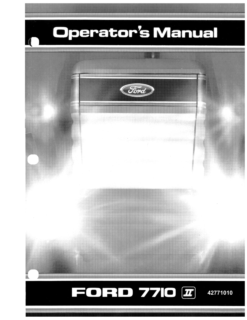
Ford 7710 II Tractor Operator’s Manual Instant Download (Publication No.42771010)
Please open the website below to get the complete manualnn//
Download Presentation

Please find below an Image/Link to download the presentation.
The content on the website is provided AS IS for your information and personal use only. It may not be sold, licensed, or shared on other websites without obtaining consent from the author. Download presentation by click this link. If you encounter any issues during the download, it is possible that the publisher has removed the file from their server.
E N D
Presentation Transcript
DEAR CUSTOMER - PLEASE READ CAREFULLY The warranty coverage that is extended to your Ford Tractor is explained in the Warranty and Umitation of Uability, Ford Tractor and Equipment form, Yow: dealerwiU provide you with a copy of the warranty and retain a copy which you have signed, After you read the warranty, ask your dealer to explain any points that you may not understand. Do not modify or alter or permit anyone else to modify or alter this tractor or any of its components or any tractor function without first consulting a Ford Tractor Dealer. If you have any questions regarding tractor modifications contact Ford Tractor Operations of Ford Motor Company. A roll over protective structure (ROPS) and seat belt were standard equipment for the tractor at time of factory assembly, If the ROPS was deleted by the original purchaser or has been removed, it is recommended that you equip your tractor with a Roll Over Protective Structure (ROPS) and seat belt ROPS and safety cabs are effective in reducing injuries during tractor overturn accidents. Overturning a tractor without a ROPS or safety cab can result in serious injury or death. Roil Over Protective Structure (ROPS) safety cabs and seat belts are available for your Ford tractor. If your tractor is not equipped with a ROPS or safety cab and seat belt see your Ford Tractor Equipment Dealer. Your safety you use while operating this equipment. Read the safety precautions carefully. the safety of those around you depends upon the care and good judgment a complete list of the pre delivery service checks performed by your dealer, refer to PRE DELIVERY SERVICE on the upper portion of the following two pages. The first copy is your record of the service performed and the second copy, which is to be removed from the manual, is your dealer's record. MAKE SURE THAT YOU AND THE DEALER SiGN BOTH COPIES. After you have operated yow: tractor for fifty hours, take the manual and your tractor to your dealer. He will then perform the :factory recommended SO HOUR SERVICE as listed on the lower portion of the following two pages - without charge - except for lubricants, hydraulic oil, or filters replaced as part of normal maintenance. MAKE SURE THAT YOU AND THE DEALER SIGN BOTH COPIES. Your tractor is equipped with a new Ford engine. During manufacturing, the cylinder walls of some engines are sleeved. Both sleeved and unsleeved engines have the same operating characteristics. PARTS AND SERVICE CATALOGUES AVAILABLE! Ford Tractor Operations is pleased to announce to owners of Ford tractors and equipment the availability of numerous parts and service catalogues. To obtain these catalogues merely fill out the order form available from yow: local authorised Ford Tractor-Equipment Dealer. Mail VlIth your remittance to Helm Inc. Your order will be processed promptly.
https://www.ebooklibonline.com Hello dear friend! Thank you very much for reading. Enter the link into your browser. The full manual is available for immediate download. https://www.ebooklibonline.com
PRE-DELIVERY SERVICE CHECK AND ADJUST AS REQUiRED INOPERATIVE SERVICE CHECKS; 20. Hydraulic lift draft control m ~ i f \ " l r w l f 1 t ! adjustment 3. Windsh iald wiper/washer 2 Sflt'h,,'tl drawbar and pin in !. Tire pressure Front wheel t o e ~ i n 3. Front and rerv wheel disc and hub nuts for tightness" 4 Rear wheel to ,im clamp bolts, lock 0, lack screws 8. 9. Hv,jralJllc 5. condition 27. Cab door lock operation 28. Seat adjustment 29. intenor upholst!lry.l!im and Control rocker for tension and compression loads,,, .. AuxH'3ty service control or remOle control valve 10. Fluid and oil leaks 11. Seat belt and rollbars properly 6. 7 R 30. 9. 31. 32. 33 34. 10, 11- 12 13. 14. Oil level in injector pump .. 15. Fuel level 16. Battery cleanliness, vent Onf"1IrlflS elecln)Mte level, and not less 1 .240 Check all electrical cables and wire routings are away from sharp moving parts and exhaust 18. Power 5reering reservoir 01 I level.. 19. Hydraulic system oil level O t l ' 8 ( R t o r ~ Manual ........ .1 oil diesel luel PERFORMANCE SERVICE CHECKS operation including throttle OPERATIVE SERVICE CHECKS; All operating chacks afe to hi! performed with the tractor at normal 1. Starter 2 Lights and proper operation temperature. 4. 5. 6, accessories TRACTOR MODEL NO TRACTOR SERIAL NO. INSPECTION PERFORMED PRECAUTIONS AND WARRANTY EXPLAINED SAFETY OWNER'S SIGNATURE -----------------------.---- ..... ------------- DATE DEALER'S SIGNATURE DATE 50-HOUR SERVICE CHECK AND ADJUST AS REQUIRED INSPECTION PERFORMED SAFETY PRECAUTIONS AND WARRANTY EXPLAINED TRACTOR MODEL NO. TRACTOR SERIAL NO. r I OWNER'S SIGNATURE DATE DEALER'S SIGNATURE DATE ~
PRE-DELIVERY SERViCE CHECK AND ADJUST AS REQUIRED 20. Hydraulic lift draft control mainspring adjustment ."" ................. ,," .... C1 21. link drawbar and pin in 3, Windshield wiper/washer 2 speed operation .,,, ... ,, .......... ,, ................... ,, ............ 0 4, Heater temperature controL, ................... C1 5. Pressurizer fan 3 speed operation ......... .. 6, Air conditioner oparetion ........................ 0 7. Ensine maximum no-load speed adjustmant and fuel 8. PTO engagement and disengagement ... 9. Hydraulic system; Draft and Position Control operation ........ ,." ........ "., ................. .. Draft Control rocker for tension and compression loads .............. .. Auxiliary service control or rarnote control valve ........................................... , 10, Fluid and oil leeks ...................... " ..... """ ... 0 11. Seat belt and roUbars properly installed ..... " ........ , ......... , .. ,., .... , ... "" ..... """". 0 INOPERATIVE SERVICE CHECKS: 1. Tira pressura 2. Front wheel toe-in "."., .. , .... """",.,.,.", .. ", 0 3, Front and raIIr wheel disc and hub nuts for tightness" ......... " .. C1 4. Reer whee! to rim clamp bolts, lock nuts. or jack screws for tightness, ............ , .. "","' .......... """""" .. , [] 5, Front axle spindle nuts for proper tightness ." ...... " ... , ............. 'w .... , ..... C1 6. Front axle support bolts for tightness ... """,." .. , .... ", .... .,.,." ..... ., .. .,.,., [] 7, Chack front axle differential oil level (Front wheel drive only) ,.." ...... " .. ,,, " ....... C1 8. Chack front axle hub oil level (Front wheel drive only) .. , .. , ...... ., ........ , .... [J 9, Check front weight mounting bolts for tightness ..... " .... " .. ,., .......... """", ......... , .. 0 10, Radiator coolant level ....................... "" .... , 0 11, All belt tensions ................... ,' .... " ............ , .. i.J 12. Engine oil leveL ...................... " ................. C1 13, Drain diesel fuel filter .............................. ", [] 14. Oil level in injector pump .. , ...................... 0 15. Fuel Ieve! .. "" .. ., .. ,, .......................... , ..... , ...... , 0 16. Battery cleanliness, vent openings. electrolyte level. and specific gravity not less than 1 ,240 ......... ., ... " .. " .... , .. "" .... ' 0 17. Check aU electrical cables and wira routings are away from sharp edges, moving perts and exhaust heat .. , .. , .. " ........................ ", ..... " .. " [] 18. Power steering reservoir oil leveL"' ....... [] 19. Hydraulic system oil !eve! ,.",." .. " .. , .......... [] CJ 22, rod levelling crank for proper operation """ ... " ...... " .. " .. "", ....... " .. 23. Clutch pedal free travel "'."",.", ..... " ... " .... 24. Brake pedal free travel, equalization. pedal lock."""""" ............ " .. ,,,,, .. ,, ... ,, ...... ,,,, 25. Parkins brake oparation ... "" ...... , ...... "" .... 26. Cab door operstion and see! condition " ...... ,,,., ............... ,,,.,,"" ............... . 21. Cab door lock operation .......................... . 28, Seat adjustment "' .... " ..... , .......................... , 29, Cab intarior upholstery, trim and moldings ".,,, ......... ,., ..... ,, ................ , ... ,., .... CJ 30, Cab window oparation. window props and latches, seal condition" .. " ..... , 31. Cab SUfi visor operation ........ " ................ .. 32. Cab filter installation ................. '"""" ........ [] 33, Tool box for Operators Manual .............. . 34. Sheet metal and peint condition ........... .. idle [] PERFORMANCE SERVICE CHECKS 1, Engine operation including throttle and governor operation ............................. 0 2. Transmission including clutch ................. 0 3. Differential lock engagement and disengagement .",., ... , ..... " ..................... , .. , .. LJ 4, Steering controL ........................................ [J 5. Brake action ... , ............. , ............................... 0 6, AI! OPtional equipment and accessories .. , .... , .. , ........ ,., ............................. C1 OPERATIVE SERVICE CHECKS: AU oparating checks afe to be performed with the tractor at normal operating temperatura, 1. Starter salety switch operation ............ , ... 0 2. lights and instruments for propar operation .......... , ........... , ........... " ..... [] INSPECTION PERFORMED - SAFETY PRECAUTIONS AND WARRANTY EXPLAINED TRACTOR SERIAL NO. ------ DATE DEALER'S SIGNATURE DATE OWNER'S SIGNATURE SERVICE 5 O ~ H O U R CHECK AND ADJUST AS REQUIRED 1, Change Engine Oil and Filter 2. Change Hydraulic Inlet Filter .. , ...................... "" ......................... ,.,.,.,., ............................. " .. " .. " ................ . 3, Drain Fuel Filter and Bleed System ........................ "" ..................................... " .............................. "" ....... Cl 4, Change Injection Pump Oil .. ",,,,, ............... ,, .... , ....................... " .. " .. "" ... " ...... " ............. " ....................... .. 5, Tighten Pump Delivery Valve Holders""' .. " .. """ ... , .. , ......... "" ........... " ...... " .... , ... , ............ , ... ,,,."", .......... , 6. Chack Cylinder Head Bolt Torques and Adjust Engine Valve Clearance ................................ "" ..... " 7, Check and Adjust Belt Tension ..... " ...... , ........ , ................................................................................ , ........ .. 8, Chack and Adjust Brake and Clutch Linkage .......................................................................................... 0 9. Check Torque on Front and Rear Wheel Lug Nuts ............ , ...................... " ...... ,,,,,,, , ............. " ............. CJ 1(). Chack Torque on Rear Wheel Rim-ta-Disc Clamp Bolts ............................................ " ....................... C1 11. Chack Torque on Front Weiqht Clamp Bolts and Weight Hanger Mounting Bolts ......... ,,,,, .. , .... ,,. CJ 12, Change Front Axle Differential Oil {Front Wheel Drive Only} ..... , ...................... , ........ ,.,., ... , .. "." ........ 0 13. Change Front Axle Hub Oil (Front Wheel Drive Only) ............................. " ......................... " ............... [] TRACTOR MODEL NO, ~ INSPECTION P PRECAUTIONS AND WARRANTY EXPLAINED TRACTOR SERIAL NO. ~ ~ - - - E R F O R M E D ~ S A F E T Y DATE DEALER'S SIGNATURE OWNER'S SiGNATURE DATE
FOREWORD This Manual has been prepared to assist you in the correct procedure operation and maintenance of your new Ford Tractor. The Manual covers tractors IAlith and less cab where obvious occur both versions are illustrated or described in text running-in, Your tractor has of operation under a IAlide variety of operating conditions. Prior to delivery, the tractor was carefully inspected, both at the factory and by your Ford tractor dealer to ensure that it reaches you in optimum condition. To maintain this condition and ensure trouble-free operation, it is important that the routine services, as specified in this Manual, are camed out at recommended intervals. built to maximum performance, economy and ease Read this Manual carefully and keep it in a convenient place for future reference. If at any time you require advice concerning your tractor, do not hesitate to contact your authorised Ford tractor dealer. He has factory trained personnel, genuine Ford parts and the necessary equipment to carry out your service requirements. A vehicle identification plate is located under the radiator cap access panel. If your tractor is equipped IAlith front wheel drive transmission, then a similar plate is affixed to the rear of the front casing. For convenience, the numbers shown on the plates should be recorded in the panels beloo; and quoted to your Ford tractor dealer should the tractor require service. OMroa Vehicle Identification Plate Front Axle Identification Plate Ford policy is one of continuous improvement. and the right to change prices, specification or equipment at any time Without notice is All approximate only and the illustrations do not necessarily show tractors in standard condition exact information about any particular tractor please consult your Ford tractor in this book is subject to production variations. Dimensions and weights are (i)
SAF TY PRECAUTIONS A careful accidents who are responsible end Is the best operator. Most accidents can be avoided by observing certain precautiot'lS. and take the before operating the tractor. n,.,,,nH1 m so. THE TRACTOR 9, The fuel oil in the injection system is under high pressure and can penetrate the skin. Unqualified persons should not remove or attempt to adjust a pump, injector, nozzle or any other part of tbe fuel Fa!lure to foJlovJ these instructions can Read the Operator's Manual carefully tractor. Lack of operating knowledge can lead to accidents, using tOO 1. 2, with a RaPS or for safe operation. or injuf!." If your tracior 10, Continuous long term contact with used caused skin cancer in animal tests. contact with used engine oiL Wash skin nu,mt)t!u soap and water, Is not equipped with a seat belt, see your Ford Tractor Equipment Dealer, If a front end loader is to be installed, always use a FOPS canopy to avoid injury from falling objects. 3. OPERATING mE TRACTOR 4, Use the nandholds and step plates when getting on and off the tractor to prevent falls, Keep steps and platform cleared of mud and debris. Apply the parking brake, "Off" position, the lift control lever in the down position, the remote control valve levers in the neutral position, and the transmission in neutral before starting the tractor, the P,T,O. lever in the Do not tractor, 5. anyone but the operator to ride on the is no safe for extra riders. Replace aH missing, illegible, or damaged safety decals, 6. 2, Do not start the engine or operate controis while standing beside the tractor, Always sit in the tractor seat when starting the engine or operating the controls, 7. Keep safety decals dean of dirt and grime. SERVICING THE TRACTOR Do not bypass the neutral start switch, Consult your Ford tractor dealer if your safety start controls malfunc- tion, Use jumper cables only in the recommended manner, use can result in a tractor runaway. 3, The cooling system operates under pressure which is controlled by the radiator cap. It is dangerous to remove the cap while the system is hot. Always tum the cap slowly to the frrst stop and allow the pressure to escape before removing the cap 1. 4, AVOid accidental contact with the gear shift lever while the engine is running. Unexpected tractor movement can result from such contact, Do not smoke while refuelling the tractor. type of open flame away. Walt for the engine to cool before refuelling, 2. any Do not get off the tractor while it is in motion. 5, Keep the tracior In good operating condition for your safety. An improperly maintained tractor can be haz- ardous, 3. 6, Shut off the getting off apply the parking brake before To prevent flre or explosion' keep open flames away from battery or cold weather starting aids, To prevent sparks which could cause an explosion use jumper cables to instructions. 4, Do not park the tractor on a steep lndlne, 7, Do not operate the tractor engine in an enclosed building without adequate ventilation. Exhaust fumes can cause death, 8. 5, Stop the engine before performing any service on the tractor. 9, If the power steering or engine ceases operating, stop the tractor 6. h y d r a u ~ c / d i e s e l flUid under pressure can penetrate the skin causing serious Injury, DO NOT use your hand to check ror leaks. Use a piece of cardboard or paper to search for leaks. Stop the engine and relieve pressure OOfore connecting or dtsconnecting lines. all connections before pressurlzlng lines, If fluid is injected into the skin obtain medical attention immediately or gangrene may result. 10. pun only from the swinging dnawbar or the lower unk drawbar in the down position, Use only a drawbar pin that locks in Pulling from the tractor rear axle or upset engine or 11. If the front end of the tractor tends to rise when heavy install front end or front wheel weights, tractor with a light front end. not operate the Do not attempt to service the air conditioning system, It is possible to be severely frostbitten or injured by escaping See your dealer for service. 12. Always set the control when porting equipment. properly mounted and \NiH disconnect safely in case of accidental detachment of implement. selector lever in position equipment and when trans- sure hydraulic couplers are Do not modify or alter or permit anyone else to modify or alter this tractor or any of its components or any tractor function without first consulting a Ford tractor dealer. 8. 13, Do not leave equipment in the raised position. (ii)
SAFETY PRECAUTIONS DIESEL FUEL DRIVING THE TRACTOR L alcohol or These com!A- 1. blended fuels be added to nations can create an increased fire or explOSive hazard. In a dosed container such as a fuel tank such blends are more explosive than hlends. 2. To avoid upsets drive the tractor with care and at conlpaltlble v.4th 1:l1ing over rough ground. and when turning comers. Do not use these when oper- crossing ditches or 2, Never f l11OVe the fuel cap or refuel with the engIne running or hot 3. To provide two whee! pedals when transporting on roads. lock the tractor brake 3, Do not smoke while refuelling or when standing near fuel. 4. Maintain control of the fuel fiUer pipe nozzle wben fillIng the tank. 4. Keep the tractor in the same gear when going downhill as used when going uphill. Do not roast or free wheel down hills. Do not fill the fuel tank to capacity. Allow room for expansion, 5. 5. Any towed vehicle whose total weight exceeds that of the towing tractor must be equipped with brakes for safe operation. 6. Wipe up spilled fuel immediately. Always tighten the fuel tank cap securely. 7. When the tractor is stuck or tyres are frozen to the ground, back up the tractor to prevent upset 6. If the original fuel tank cap is lost, approved cap. A non-approved, proprietary cap may not be safe. 8. it with a Ford 7. Always check overhead clearance, especially when transporting the tractor. 9. Keep equipment dean and properly maintained. 10. Do not drive equipment near open fires. 8. Dip the tractor lights when meeting a vehicle at night Make sure the lights are adjusted to prevent blinding an oncoming vehlde operator. 11. Never use fuel for cleaning purposes. 12. Arrange fuel purchases so that winter not held over and used in the spring. fuels are 9. North An1er1ca only: Use the Rasher/Tum Signal llghls and SMV sign when travelling on puhl!c roods, both day and night, unless prohihited by law. SAFETY CAB OR FRAME (Where fitted) If your Ford tractor is equipped v.4th a safety cab or frame it must be maintained in a serviceable condition, Be careful when driving through doorways or working In confined spaces with low headroom. OPERATING THE P.T.O. L When operating P.TD, driven equlpment, shut off the engine and wait until the P.T.O. stops before gelling off the tractor and dtsconnecting the equipment. Under no circnmstances: L - - - modify, drill or alter the safety frame or safety cab in any way as so could render you liable to legal prosecution. 2. Do not wear loose take-off or when near rotating eqUipment when operating the power 2. - - - attempt to straighten or weld any part of the main frame or retaining brackets whlch have suffered damage. By doing so and endanger your may weaken the structure When operating stationary PT.o. driven equipment, always apply the tractor parking brake and block the rear wheels front and back 3. 3. - - - secure any parts on the main frame or attach your cab or frame with other than the bolts and nuts specitied. high 4, To avoid injury, do not P.T.O, driven equipment runnig, adjust, unclog or service the tractor engine is 4, --- attach chains or ropes to the main frame or cab for puH!ng purposes. 5. 5. I l n r \ " " ' < " ' ~ ' n ! risks even your safety is in position at all times cap when the P,TO, is Whenever you see this symbol A it means: Make sure the PT.o. and not in use. the you the maximum protection ATTENTION! BECOME ALEfITl YOUR SAFETY IS INVOLVED! (ill)
ROPS (North America only) ROLL STRUCTURES OVER PROTECTIVE ROPS INSPECTION MAINTENANCE AND A ron over protective structure (ROPS) and seat belt were equipment for the tractor at time of factory assembly. If the ROPS was deleted by the original purchaser or has been removed, it is recommended that you equip your tractor with a Roll Over Protective Structure (ROPS) and seat belt ROPS are effective in reducing injuries during tractor overturn accidents. Overturning a tractor without a ROPS can result in serious Injury or death. Mer the first 20 hours of operation and after every 300 hours of operation, or six months, whichever comes first; 1. Check the torque of the ROPS mounting bolts. Tighten, if necessary, as follows: 0.75 in. bolts; 252 308 IbHt (342418 Nm) 1.00 in. bolts: 646 714 IbUt. (876 968 Nml 2, Check the operator's seat mounting bolts and the seat belt mounting parts. Tighten bolts to torque and replace worn or damaged parts. DAMAGE TO THE ROPS Roll Over Protective Structure (ROPS), and seat belts are available from your Ford Tractor EqUip- ment Dealer. If the tractor has rolled over or the ROPS has been damaged (such as striking an overhead object during transport), the ROPS must be replaced to provide the onginal amount of protection. Mer an accident, check for damage to the (1) ROPS, (2) operator's seat, (3) seat belt and seat belt mountings. Before you operate the tractor, replace all damaged parts. DO NOT TRY TO WELD OR STRAIGHTEN THE ROPS. A WARNING: Never attach chains, ... ropes, or cables to the ROPS or Cab for pulling purposes; this will cause backward. Always pull from the tractor drowbar. A WARNING: If the ROPS cab is ... removed or replaced, make certain that the proper hardware is used and the recom- mended torque values are ching bolts. A WARNING: Always wear your seat ... Never wear is not equipped with a ROPS or Safety Cab. FALLING OBJECT STRUCTURES (FOPS) -- 2 Post ROPS tractor to to atta seat belt if the tractor PROTECTIVE When tractors are equipped with front-end load ers and are not equipped with rp(',r;m'mP1nlic'li the tractor cabs, it is Ford Built Safety Cab (ROPS) (Iv)
UNIVERSAL SYMBOLS your tractor, various symbols are symbols a to the operation on the below instruments ... II Engine speed (rev/minx 100) Remote cylinder (extend) (il Ai tV! t ~ p e r a t u r e control ~ Hours recorded Hazard warning coolant @Neutral 4:;':" Remote (float) temperature "" Fan Fuel level .... 'Tortoise', slow or minimum setting Wipe/wash control Engine stop control 'Hare', setting ! I Power take-off engage ...... ~ or maximum Lights I Power take-off disengage I .. ~ .. Transmission oil pressure ~ Hom "r Front wheel drive iii engage , Tum signal oil pressure tt Front whee! drive Itt disengage ..... Transmission oil temperature Alternator charge TT Heater temperature W control OM499A ( '\to Work ~ Parking brake arm/lower OM484 (v)
CONTENTS Page (i) (U) foreword safety precautions roll over protective structures (North America only) universal symbols (iv) (v) SECTION A CONTROLS, INSTRUMENTS AND OPERATION tractor controls engine starting/stopping procedure transmission dual power front wheel drive safety cabs operator's seat power take-off belt pulley hydraulic controls remote control valves three-point linkage track adjustment tractor weighting tyre inflation .2 4 8 9 9 10 18 20 21 22 30 33 44 50 53 SECTIONB LUBRICATION AND MAINTENANCE lubrication and maintenance chart routine servicing general maintenance .2 3 23 SPECIFICATIONS SECTIONC INDEX (vi)
--FORD 1110 SECTION A CON ROLS, INSTRUMENTS AND OPERATION The following pages in this section detail switches and this section carefully and ensure you are thoroughly familiar with all aspects of operation. location and function or the various instruments, to or on your tractor. tractor, study This Manual covers tractors IAlith and less cab. Where there are obvious differences in location, appearance or operation of any of the controls, then each version is illustrated or described in the text If in doubt about any aspect of operation of the tractor, consult your Ford tractor dealer. Particular attention should be paid to the recommendations for running-in to ensure that your tractor 1AIil1 long and dependable seMce for which it was rf,,",nn,>rf 1
PANEL a 2, P1"oofmete1" in this section correct 2
--FORD 7710------------SECTION A When the switch will whee! light intenslty is drive is switch is turned on, the rocker internally illuminated. When front is the when front wheel is brightly lit Key-Start Switch Actuates the starting motor and Thermostart (where fitted). See "KEYSTART SWITCH" in this section for correct operating procedure, 1. Instrument Panel Engine Stop Control Pull fully 'OUT' to cut the fuel supply to the injectors and stop the engine. The stop control must be pushed fully 'IN' before re starting the engine. 1. 2. 3. 4, Alternator warning light Turn coolant temperature gauge Trailer tum signal indicator llghts (except North Amer- ica) Proofrneter Fuel gauge Engine oU pressure warning light Air cleaner t striction warning Dua! power indicator lamps indicator 5. 6. 7. 8. 9. Cigarette Ughter To operate, push the lighter knob fully in. The lighter will pop out when the electrical element has reached the correct temperature. HAND CONTROLS AND SWITCHES An ashtray is provided on the left-hand side of the cab, in front of the parking brake. NOTE: The following text describes the function of the various switches and hand controls on your tractor. See Figure 2 to locate these features on your tractor. Tractor Lights Switch The rocker switch is of the 3-way type, the rear position being off, the centre position actuating the side lights and the foremost position actuat ing the headlights. Selection of main or dip beam is by means of the stalk-type switch mounted on the steering column. Hand Throttle Lever Push forward to progressively increase engine speed. Fuel Tank Sender Switch The switch is used to monitor the fuel level in the upper and lower tanks, See "Fuel Gauge" on page 2 of this section for correct operating procedure. Work Lamp Switch The rocker switch is of the 3-way type, the front position controlling the front work lamps, the centre position being off tion controlling the rear work lamps. Front and rear work lamps may be illuminated simulta- neously by first moving the switch to the forward position, then qUickly to the rear position. the rearmost posi- Front Wheel Drive Engagement Switch (where fitted) Press green section engage the drive to the front wheels. Press the black section of the switch to drive. will tum a short Moving the switch to the centre off the rear work lamps, followed, time delay, by the front work lamps. The switch is illuminated when the rear worklamps are on. switch to front 3
Suggest: If the above button click is invalid. Please download this document first, and then click the above link to download the complete manual. Thank you so much for reading
.... -..r!ilt:COJfiROLS, INSTRUMENTS AND OPERA TION--- NOTE: The horn, headlight flash and turn signals wilt only operate when the key.start switch is turned on. Hazard Warning Lights Switch Press the red secti'On 'Ofthe rocker switch (mangle symbol) to 'Operate ali the tum signals simulta- neously. The switch is internally iUuminated and will flash in unison with the tum Signals. NOTE: In North America hazard warning lights are used when driving on the public highway. \tVhen a tum signal is made. the lights on one side of the tractor wiil flash, indicating a tum, while the lights on the other side will burn continuously. Steering Wheel Tilt Control The steering I.IIheel may be tilted if the clamp handle is pushed in against spring 'Pfessure and rotated antkloc.k\.W;e. Tighten the clamp when the steering wheel is at the desired angie. To aooid interference with the steering wheel or driver's knee, the handle should point forward and do;..vn after clamping. Re-position the handle, as necessary. 2. Hand Controls and Switches Hand throtti(;l I.wer Fuel tank SIilnOer switch 1. 2. 3, Front wh(;le! drMa engagement switch (where fitted) 4. Key-start switch 5. Engine stop rontrol 6. Ogarette lighter 7, Tractor lights switch 8. Work lamp switch 9. Multl fu:nction switch 10. Hazard wamlng lights switch 11. St(;loo'ng ~ tilt control IMPORTANT: Your tractor is equipped with hydrostatic power steering. Neuer hold the steer- ing wheel against either of the steering stops for more than 10 seconds or for more than a total oj 10 seconds in anyone minute. Fa!lure to observe this precaution may result in damage to the steering system components. Multi-Ft.metie Switch The stalk-type ~ t c h is mounted on the steering column. The switch operates the hom, tum signals and headlarnp flash and is also used to select main or dipped beam. KEY-START SWITCH A ... Therrn'Ostort. If, in an emergency, it is necessary to use ether with Thermostart installed, disconnect the terminal wire from the glow plug on the rear of the intake maniJord and insulate the free end oj the wire. WARNING: Do not use ether with the Press in the end of the stalk to actuate the hom. The stalk win operate the right-hand tum signal, if moved clockwise, and the lef1;.hand tum signal, If moved anti clockwise. The tum signal warning light (and trailer lights, if connected), will also flash when the tum signals are operated. All tractors have a five-positi'On key-start switch. See Figure 3 and the following text NOTE: North America only: The turn signals will only operate if the hazard warning lighl$ are switched on. Your tractor may be equipped with the Thermostart cold weather starting aid which is effective in temperatures down to -18"C (O F). The Thermo- start consists of a heating element installed in the inlet manifold VJhen operated b; the key-start switch, the Thennostart will ignite fuel in the manifold prior to it entering the combustion chamber. With the headllghts switched on, push the stalk downwards to select main beam. The blue warn- ing .light on the proofmeter will also iUuminate. Pull the stalk back to the central position to select dip beam. Pull the stalk further back. against spring pres- sure, to flash the headlight main beam. The sialk wiU automatically return to the central, dip beam position when released. IMPORTANT: Never push or tow the tractor to start the engine. Doing so may overstress the drive-train and damage the Dual Power. 4
https://www.ebooklibonline.com Hello dear friend! Thank you very much for reading. Enter the link into your browser. The full manual is available for immediate download. https://www.ebooklibonline.com


