Exploring Sensing Circuits and Resistance Variations
Dive into the concepts of potential difference, resistance variations in sensors like thermistors and LDRs, and the application of sensing circuits in real-world scenarios. Understand how resistance changes with temperature and light intensity, and learn to calculate voltages and currents in sensing circuits. Discover the impact of light level changes on LDR resistance, voltage across components, and circuit current. Delve into practical examples like central heating systems and lighting circuits that utilize sensing circuits for automatic operation based on environmental conditions.

Download Presentation

Please find below an Image/Link to download the presentation.
The content on the website is provided AS IS for your information and personal use only. It may not be sold, licensed, or shared on other websites without obtaining consent from the author. If you encounter any issues during the download, it is possible that the publisher has removed the file from their server.
You are allowed to download the files provided on this website for personal or commercial use, subject to the condition that they are used lawfully. All files are the property of their respective owners.
The content on the website is provided AS IS for your information and personal use only. It may not be sold, licensed, or shared on other websites without obtaining consent from the author.
E N D
Presentation Transcript
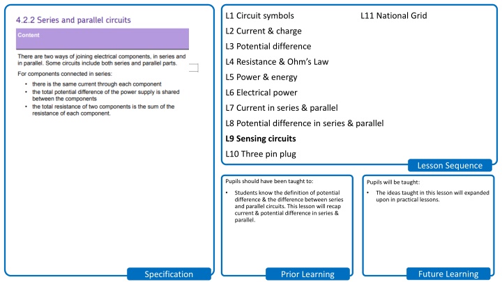
L1 Circuit symbols L11 National Grid L2 Current & charge L3 Potential difference L4 Resistance & Ohm s Law L5 Power & energy L6 Electrical power L7 Current in series & parallel L8 Potential difference in series & parallel L9 Sensing circuits L10 Three pin plug Lesson Sequence Pupils should have been taught to: Pupils will be taught: Students know the definition of potential difference & the difference between series and parallel circuits. This lesson will recap current & potential difference in series & parallel. The ideas taught in this lesson will expanded upon in practical lessons. Future Learning Specification Prior Learning
SciDoc Sensing circuits Sensing circuits Last Lesson Last Term Last Year Stretch & Challenge I do We do You do Test I do We do You do Do Now
SciDoc Keywords Learning Objectives Keywords Sensing Thermistor LDR Resistance Voltage Current Recall what happens to resistance of a thermistor/LDR as the temperature/light intensity increases. Recall how sensing circuits can be used. Calculate resistances, voltages and currents in sensing circuits. I do We do You do Test I do We do You do Do Now
As the temperature increases, the resistance of a thermistor decreases. SciDoc As the light intensity increases, the resistance of an LDR decrease. Stretch: How will the following vary if the light level increases: a) Resistance of the LDR. b) Voltage across the LDR. c) Voltage across the resistor. d) Overall current in the circuit. I do We do You do Test I do We do You do LO:
If the light level increases: a) Resistance of LDR will decrease. b) Voltage across the LDR will decrease. c) Voltage across the resistor will increase. d) Overall current in the circuit will increase. SciDoc Stretch: If the resistance of the LDR is 150 , what is the: a)Current in the circuit. b)Voltage across the resistor. I do We do You do Test I do We do You do LO:
Sensing circuits are used in: Central heating that turns on automatically when it s cold. Lighting circuits that turn on when it s dark. SciDoc Stretch: If the resistance of the LDR is 150 , what is the: a)Current in the circuit. b)Voltage across the resistor. I do We do You do Test I do We do You do LO:
SciDoc When light intensity is 45 lux: 1. What is the resistance of the LDR? 2. What is the total resistance of the circuit? 3. What is the current in the circuit? 4. What is the p.d. across the fixed resistor? 5. Will the street lights be on or off? I do We do You do Test I do We do You do LO:
SciDoc Worksheet Worksheet Complete the worksheet! I do We do You do Test I do We do You do LO:
SciDoc Basic answers Basic answers 1. From graph; R = 500 2. 1000 + 500 = 1500 3. V = I x R I = V R = 6 1500 = 0.004 A 4. V = I x R = 0.004 x 1000 = 4 V 5. Over 3 volts, so street lamps off. I do We do You do Test I do We do You do LO:
SciDoc 6. From graph; R = 2000 7. 1000 + 2000 = 3000 8. V = I x R I = V R = 6 3000 = 0.002 A 9. V = I x R = 0.004 x 1000 = 2 V 10. Under 3 volts, so street lamps on. I do We do You do Test I do We do You do LO:
SciDoc 11. Total resistance = 2000 I = V R = 6 2000 = 0.003 A 12. 2000 13. 1000 14. 45 lux I do We do You do Test I do We do You do LO:
SciDoc Resistance of LDR is 900 at 50 lux. Therefore variable resistor needs resistance of 900 to split voltage with LDR. I do We do You do Test I do We do You do LO:
SciDoc Struggle time! Struggle time! Exam question so exam conditions! You have 10 minutes. I do We do You do Test I do We do You do LO:
SciDoc Current I do We do You do Test I do We do You do LO:
As temperature increases, resistance of thermistor decreases. [1] This decreases overall resistance in circuit. [1] So (due to V = I x R), current on ammeter decreases. [1] Reading on voltmeter across thermistor would decrease. [1] Due to voltage splitting in series. [1] Vice versa if temperature SciDoc I do We do You do We do decreases. [1] Test I do You do LO:
SciDoc R = V I I = 3.5 mA = 0.0035 A R = 4.2 0.0035 A = 1200 [1] [1] [1] Q = I x t t = 5 mins = 300 s Q = 0.0035 300 = 1.05 C [1] [1] [1] I do We do You do Test I do We do You do LO: