Evolution of Digital Radiography in Medical Imaging
Explore the evolution of digital radiography in medical imaging, from the invention of CMOS in 1963 to the development of Gadolinium-based flat-panel detectors in 1997. Learn about the advantages and challenges of digital imaging technology and its impact on the field of radiography.
Download Presentation

Please find below an Image/Link to download the presentation.
The content on the website is provided AS IS for your information and personal use only. It may not be sold, licensed, or shared on other websites without obtaining consent from the author.If you encounter any issues during the download, it is possible that the publisher has removed the file from their server.
You are allowed to download the files provided on this website for personal or commercial use, subject to the condition that they are used lawfully. All files are the property of their respective owners.
The content on the website is provided AS IS for your information and personal use only. It may not be sold, licensed, or shared on other websites without obtaining consent from the author.
E N D
Presentation Transcript
5/19/2023 DIABETES MELLITUS 1
Digital Radiography Digital Radiography 2
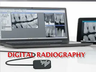
Digital imaging Digital Imaging is any modality / method of imaging that creates an image that can be viewed or stored on a computer. Digital Radiography 3
Introduction Digital technology in the capture, display, enhancement, and storage of direct radiographic images. Digital imaging offers some distinct advantages over film, but like any emerging technology, it presents new and different challenges for the practitioner to overcome. imaging incorporates computer Digital Radiography 4
History Year 1963 Development CMOS invented 1969 CCD technology for video applications Method of converting the informationpattern into a digital form 1975 1980 Computed radiography - storage phosphors Computed Radiography PSPmethod Kodak Ekta speed 1981 Digital Radiography 5
History Y ear Development Amorphous selenium based image plates 1987 Charge-coupled device (CCD) slot-scan direct radiography Storage phosphor system, DIGORA for intraoral use. 1990 1994 Computed Dental Radiography (CDR) system by Schick. Amorphous silicon cesium iodide (scintillator) flat-panel detector Selenium-based flat-panel detector 1995 Pasler,Pocket Atlas of Dental Radiology, Thieme2007 Digital Radiography 6
Year Development 1997 Gadolinium-based (scintillator) flat-panel detector Gadolinium-based (scintillator) portable flat-panel detector Dynamic flat-panel detector fluoroscopy 2001 2009 Wireless DR (flat-panel detector) Digital Radiography 7
WHAT IS A DIGITALIMAGE Method of capturing radiographic Image Sensor Break in Electronic pieces Present and Store Computer Digital Radiography 8
Pixel In digital imaging, a pixel [picture element] is the smallest controllable represented on the screen element of a picture Digital Radiography 9
Analogue to Digital Conversion Digital images are numeric and discrete in two ways: (1) in terms of the spatial distribution of the picture elements (pixels) and (2) in terms of the different shades of gray of each of the pixels. Digital Radiography 10
ADC consists of 2 steps Sampling Quantization Digital Radiography 11
Sampling Sampling means that a small range of voltage values are grouped together as a single value Digital Radiography 12
Sampling Digital Radiography 13
Quantization Digital Radiography 14
Equipment An x-ray machine Digital image receptor a sensor An analog-to-digital converter Computer and monitor with appropriate hardware, software, networkconnection Printer Digital Radiography 15
ACQUIRING A DIGITAL IMAGE INDIRECTMETHOD scanners cameras Digital Radiography 16
DIRECT METHOD 1. Solid state technology: Charge coupled device Complementory metal oxide semiconductors Flat panel detectors 2. Photostimulable phosphor plate Digital Radiography 17
Charge coupled device Introduced in 1987 1st intraoral digitalreceptor Consist of thin wafer of silicon with electronic circuit Consist of matrix, amplifier in plastic housing Digital Radiography 18
Structure Digital Radiography 20
Exposure to radiation Break the covalent bond in silicon atoms Produce electron hole pair Electron attracted towards most positive potential in device create charge packet Charge pattern formed from individual pixels forms latent image Digital Radiography 21
Bucket brigade form of charge transfer Finally transferred to amplifier Transmitted as voltage Analog to digital converter Image display Digital Radiography 22
Mechanism e- Digital Radiography 23
CCDLinear array made up of few px wide and many px long Area array Digital Radiography 25
Linear array Digital Radiography 26
Area array Digital Radiography 27
Advantages Intact images or real time image production and display. Consistent quality X ray sensitivity is 80% greater than conventional film. Elimination of hazardous chemicals used in film processing and lead foil. Computer aided diagnosis Digital Radiography 28
Disadvantages High initial cost of system Unknown life expectancy of CCD sensor Rigidity and thickness of the sensor CCDS cannot be sterilized Hard copy images fade with time Digital Radiography 29
Disadvantages Image manipulation can be time consuming. The sensor may not be well tolerated by patients -more time-consuming The cable attached to the sensor is easily damaged and may interfere with sensor Actual area available for image capture may be as little as 60% of the sensor area Digital Radiography 30
Complementary metal oxide semiconductors Each pixel is isolated from its neighboring pixels and connected to transistor Electron hole pair generated withinpixel Charge tranfer to transistor in formof voltage Each transistor voltage is read out separately by frame grabber Stored and displayed as digital gray value Digital Radiography 31
AD C Digital Radiography 32
Flat panel detector Used for medical imaging, extraoral imaging device Provide large matrix area with pixel of less than 100 m Allows imaging of larger areas including head 2 types: direct indirect Digital Radiography 33
Flat panel detector Indirect flat panel detector: sensitive to visible light use intensifying screen to convert X-ray to light Digital Radiography 34
Flat panel detector Direct flat panel detector use selenium for efficient X-rays absorption Digital Radiography 35
Flat Panel Structure SANDWIC H Digital Radiography 36
Advantages Real-time process With a time lapse between exposure and image display of less than 10 seconds. Digital Radiography 37
Disadvantages Large in size so cannot be used intraorally Expensive Digital Radiography 38
Photostimulable phosphor plates storage (spp) Image plates or radiography Flexible, wireless receptors Available in the same sizes as intraoral films. phosphor plates computed Digital Radiography 39
Structure The PSP material used for radiographic imaging is europium doped barium fluorohalide. Barium in combination with iodine, chlorine, or bromine forms a crystal lattice. The addition europium (Eu + 2 ) creates imperfections in this lattice. of Digital Radiography 40
Stationary plate scans Method for "reading" the latent images on PSP plates. A rapidly rotating multifaceted mirror that reflects a beam of red laser light. As the mirror revolves, the laser light sweeps across the plate. The plate is advanced and the adjacent line of phosphor is scanned. Digital Radiography 42
Rotating plate scans Rapidly rotating drum that holds the plate Consist of Rotation of drum and fixed laser Digital Radiography 43
Advantages Storage phosphor plates can be reused indefinitely Receptor is cordless & flexible Linear or logarithmic response to radiation is available There is wide exposure range & fewer retakes Less radiation is required Digital Radiography 44
Advantages No chemical processing required Image processing of acquired images is available Images can be transferred to easily Images can be easily & inexpensively stored & retrieved Computed aided diagnosis Digital Radiography 45
Disadvantages Receptors must be erased before reuse High initial cost of the equipment Some of the image processing routines are time intensive Phosphor plates must be packaged in sterile envelopes Digital Radiography 46
Digital detector characterstics CONTRASTRESOLUTION SPATIALRESOLUTION DETECTOR LATITUDE DETECTOR SENSITIVITY
CONTRAST RESOLUTION Ability distinguish - densities Interaction of attenuation characteristics of tissuesbeing imaged Ability of computer display to portray diff in density Ability of observer to recognize differences Noise- densities captured limited by inaccuracies inimage acquisition
SPATIALRESOLUTION To distinguish fine detail Limit of resolution-function of pixel size Resolution measured- units of line pair per millimeter LINE PAIR(lp) - line & its associated space-lp/mm 2 pixels required to resolve a line pair
500px 200px 50px 10px 5px 1px DD iigg iittaa llRR aa ddiiooggrr aa pphhyy 5500
DETECTOR LATITUDE Ability of imaging receptor to capture a range of X-ray exposure Full range of densities gingiva to enamel PSP receptors larger latitude CCD & CMOS-similar to film-enhanced by contrast & brightness
