ESSnuSB Accumulator Work Plan Update

E. Wildner
08/10/14
Accumulator_Uppsala_Oct_14, E. Wildner
2
ESSnuSB
Accumulator Work Plan

NOW 2014, 10/9
E. Wildner, CERN
3
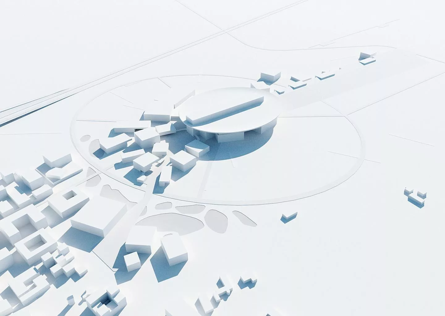
ESSnuSB on ESS site
ESSnuSB on ESS site
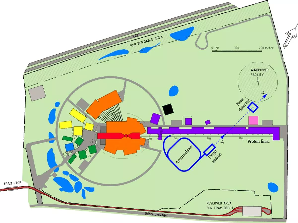
2 GeV

> 2 GeV
N
e
u
t
r
o
n
s
p
a
l
l
a
t
i
o
n
t
a
r
g
e
t
H
-

p
~1 BEuros for the neutrino facility including detector

Tord is laying out the
transfer from Linac !
08/10/14
Accumulator_Uppsala_Oct_14, E. Wildner
4
One accumulator
•
The originally proposed 4 Accelerators for accumulation seem
costly and not necessary
–
One accumulator could pulse 4 times with ¼ of the linac pulse length
•
The injection bumper is too slow
–
Rise time for the PS Booster bumpers is10 ms (same for the fall time)
–
Modern bumpers?
•
We propose to make 4 linac pulses
of length 2.86/4 ms (same beam
power)
–
They would be injected sequentially into accumulator
–
Spaced using timing such that bumpers are comfortable
–
However a price has to be payed…
NB: accumulation for ESS neutrons need H- but
considerably longer pulses at extraction from
accumulator: this is not forgotten but is less
straight forward, needs more design work
Linac Pulsing 70 Hz, present baseline
08/10/14
Accumulator_Uppsala_Oct_14, E. Wildner
5
35.7 ms
2.86 ms
28 Hz
neutron
neutrino
71.4 ms, 14 Hz
14.28 ms
0.7 ms
71.4 ms, 14 Hz
70 Hz
2.86 ms
Four Accumulators
One Accumulator
(baseline)
70 Hz linac pulsing
08/10/14
Accumulator_Uppsala_Oct_14, E. Wildner
6
Fill time of the superconducting cavities:
•
For loaded Q, this is about 0.2 ms
•
For two 3 ms beam pulses, this is 6.6% of the beam pulse length
This corresponds to an inefficiency of
6.6%
•
4 pulses at 0.75 ms and one pulse of 3 ms:
5 x 0.2 ms = 1 ms filling time,
16.6%
inefficiency (10% extra)
•
Keep in mind: 4 rings are 4 times operation and maintenance cost,
not less
•
Foil heating in accumulator (see later)
Communication D. Mc Ginnis
ESSnuSB Accumulator Lattice Version 0
SNS
C=376 m
SNS straight section for injection used
“as is” for simulations of foil stripping
Less bending strength to ease energy
upgrade
No magnet considerations yet
Collective effects not yet completed
ESSnuSB
Straight Arc
C=278 m
J. Jonnerby
H- injection foil stripping
24 m
Courtesy W. Bartmann
Injection area optics (foil/laser)
•
Contradicting requirements for foil and laser
two different
optics
settings
(however: the layout is the same!)
Foil optics
Laser optics
Courtesy W. Bartmann
•
Foil stripping feasibility: first stage approach
•
Simulations of MW accumulator projects have been done
with the ACCSIM Code.
•
The results are compared with the ORBIT results
(courtesy M. Plum, J. Holmes) for representative SNS
beams.
Feasibility of Stripping foil injection
H. Schönauer, CERN
08/10/14
Accumulator_Uppsala_Oct_14, E. Wildner
10
Comparison of Foil Heating Simulations for some Project
Lattices with the SNS
08/10/14
Accumulator_Uppsala_Oct_14, E. Wildner
11
H. Schönauer, CERN
08/10/14
Accumulator_Uppsala_Oct_14, E. Wildner
Comparison of Phase space Occupation for
100
vs. 200
normalized Emittance
For an emittance of 100
t
he
average Nr of foil hits of the
circulating beam approximately
doubles - the linac beam remains
about the same
Space Charge Detuning (approx.):
-0.15 (100
), -0.08 (200
)
12
H. Schönauer, CERN
ESS Foil (Extended SNS Lattice): Peak Temperatures
H- Linac
H- Linac+ p circulating
Maximum Foil Temperatures:
1797 K (H- Linac Beam))
2050 K (H- + p circulating Beam)
08/10/14
Accumulator_Uppsala_Oct_14, E. Wildner
13
H. Schönauer, CERN
ESS stripping foil heating considerations I
ESS stripping foil heating considerations I
Table 1: ESS beam characteristics at injection
1.
To keep constantly the foil temperature below 2500
K the pulse RMS spot size should be about 2
mm (x & y dir.) which needs betatron functions at accumulator ring injection close to 36m.
2.
Protons and electrons in H
-
having the same velocity at foil entrance (same
&
) the electron
energy is then 1.09 MeV and its total stopping power is 1.61 MeV cm2/g. So the H
-
total stopping
power is 4.98 MeV cm2/g.
M.Martini, CERN
ESS stripping foil heating considerations (2)
ESS stripping foil heating considerations (2)
M.Martini, CERN
ESS stripping foil heating considerations (3)
ESS stripping foil heating considerations (3)
Solution of the 3D heat equation with
Mathematica
for the ESS beam
Fig. 1: Time evolution of the maximum carbon foil
temperature at the pulse spot center derived from the
3D PDE (cont. line) and the simplified 1D ODE
(dotted line). Both plots differ as the 1D model does
not contain the heat conduction effect
Fig. 2: Time evolution of the carbon foil temperature
versus the foil height (y dir.). The temperature decreases
quite rapidly along the y axis (as along the x axis)
For the beam characteristics of Table 1, both figures show that the foil temperature modulation in the
repetitive accumulator filling cycles is quasi stable after the second long cycle, each made of four 0.715
ms injection pulses (repeated every 14.29 ms) plus a 14.29 ms gap (empty injection cycle). Fig. 1 shows
that the maximum stripping foil temperature varies between 1032
K and 2072
K
M.Martini, CERN
Linac Pulsing, option if current too high ?
08/10/14
Accumulator_Uppsala_Oct_14, E. Wildner
17
35.7 ms
2.86 ms
28 Hz
neutron
neutrino
71.4 ms, 14 Hz
14.28 ms
(0.7 * 2) ms, and half the intensity, for example (to mitigate high H- intensity)
How would this option influence the linac ?
71.4 ms, 14 Hz
70 Hz
2.86 ms
Four Accumulators
One Accumulator
Lower linac peak current
Extraction to 4 targets: Switch-yard
08/10/14
Accumulator_Uppsala_Oct_14, E. Wildner
18
E. Bouquerel
•
Development for EUROSB
•
ESSnuSB beam energy is lower
•
Extraction timing is different (50 Hz -> 70 Hz)
•
Needs ~ 100 ns gap in Accumulator
•
Regular gaps in linac beam (chopping)
•
Extraction from accumulator is included in this work
p-beam from Linac
08/10/14
Accumulator_Uppsala_Oct_14, E. Wildner
19
What will change for H- (simulations have to be done from the source output)
Items to change have been established and injected in the Linac upgrade plans, see for example
report from ESS visit by Gerigk and Montesinos
Linac lattice can be found in Optimus folder on the Cloud
We expect the beam conditions at exit from Linac to be available by ESS team (M. Eshraqi)
Source: Mamad Eshrakqi, email
Beam in Accumulator ??
08/10/14
Accumulator_Uppsala_Oct_14, E. Wildner
20
To be completed!
Workplan skeleton 1
08/10/14
Accumulator_Uppsala_Oct_14, E. Wildner
21
•
We would like to start he work an the planning now to get an idea
of the accumulator design, layout and price, to be refined during
“Horizon 2020”
•
The following slides organizes a few ideas (“classical”) about the
procedure
•
Small workforce, but well organized we could achieve a well set
goal.
•
The parts (have to be iterated between them) are
1.
Transferline Linac Accumulator
2.
Injection into accumulator
3.
Extraction
4.
General
5.
Lattice construction
Actors
08/10/14
Accumulator_Uppsala_Oct_14, E. Wildner
22
CERN Team
General: Elena
Consulting: Bernhard, Yannis, Brennan, Horst, Frank&Eric, Mamad
Supervision: Bernhard, Elena
Education: Bernhard
Workforce: Horst, Elena…
To some extent we will be able to use CERN competences, for accelerator physics,
clearly yes (consulting only, so far).
CERN Core team: Elena, Horst Bernard
Uppsala Team
General: Tord
Consulting:
Supervision:
Education:
Workforce:
Transfer line Linac-Accumulator
08/10/14
Accumulator_Uppsala_Oct_14, E. Wildner
23
1.
Choose extraction point (energy)
2.
Choose magnet (length, aperture…)
3.
Define transfer line lattice (stripping in magnetic elements )
4.
Debunching (
E and bunching conditions at injection, SC)
5.
Check gaps for accumulator extraction
Elena, Tord, Horst, Bernhard, Brennan, Frank, Mamad
Injection to Accumulator
08/10/14
Accumulator_Uppsala_Oct_14, E. Wildner
24
1.
Injection optics taken from SNS, to be changed?
2.
Design for foil stripping (optics)?
3.
Stripping efficiency
4.
Injection design (injection elements req.) and emmittance
estimations after injection
5.
RF
Elena, Horst, Bernhard, UU
Accumulator
08/10/14
Accumulator_Uppsala_Oct_14, E. Wildner
25
1.
Construct lattice
2.
Check the lattice with reasonable magnets
3.
Debunching (
E and bunching conditions at injection, SC)
4.
Check gap evolution for accumulator extraction
5.
RF?
6.
Estimate impedances (kickers, bumpers, cavities,
instrumentation…)
7.
Stability calculations (collective effects)
Elena, Horst, Bernhard, Frank, UU
Extraction
08/10/14
Accumulator_Uppsala_Oct_14, E. Wildner
26
1.
Responsibility of CNRS
2.
Define interface point and beam conditions at this point
General
08/10/14
Accumulator_Uppsala_Oct_14, E. Wildner
27
1.
Beam loss and radiation
2.
Controls
3.
Instrumentation
4.
Machine protection
5.
Safety (including access control)
6.
Civil Engineering
7.
Costing
Elena, Tord, Lars Söby ???, Alfredo Ferrari ???, UU and ESS
Lattice construction steps
08/10/14
Accumulator_Uppsala_Oct_14, E. Wildner
28
1.
Optimize
1.
Circumference
2.
Apertures
3.
Neutron option
2.
Can we define a new lattice in a systematic way
1.
Where to start (circumference)
2.
Magnets (aperture, length, field)
3.
Packing
4.
Injection/Extraction
5.
Characteristics of lattice for very high intensities
6.
Remedies for possible collective effects ?
7.
….etc
Lattice construction 2
08/10/14
Accumulator_Uppsala_Oct_14, E. Wildner
29
1.
High intensity / Energy
1.
Gamma transition/Isochonous ring
2.
Lattice types
3.
Phase advance
4.
Symmetry (square??)
5.
Short/long arc
6.
Straights for injection/extraction/RF/instrumentation
7.
RF at injection
Lattice design, more details 1
08/10/14
Accumulator_Uppsala_Oct_14, E. Wildner
30
0.) Paper work ...
possible articles / papers to be studied in the field:
PS-Booster Design (Bovet / Reich)
PS-Booster performance (Bovet et al)
Lattice Design of HISTRAP (Oakridge)
Design report of the RCS / Papers on the RCS lattice
(Hanke, Lachaize, Carli)
PHD Miriam Fitterer: She compared different lattices in the context of space charge
dominated beam optics & dynamic aperture
Email by Bernhard
Lattice design, more details 2
08/10/14
Accumulator_Uppsala_Oct_14, E. Wildner
31
1.) Define the geometry of the ring:
check maximum allowed dipole field by lorentz stripping
and also: available space on site
2.) define in first approximation the ring geometry <--> number of dipoles
three fold (like the RCS e.g.) / four fold / ...
which defines already a bit the tune.
3.) Scale - for the sake of comparison and experience - the space charge problem between
the accumulator ring and e.g. the PS-Booster.
4.) Symmetry arguments in the geometry layout
5) do we need dispersion free sections ?
for rf ?
for injection / extraction ?
if so do we maintain (and how) the symmetry ?
Lattice design, more details 3
08/10/14
Accumulator_Uppsala_Oct_14, E. Wildner
32
6.) Study & chose the focusing structure ...
basic cell layout
doublet / triplet / FoDo
any exotics ?
7.) and then based on this the beam optics.
Do we care about momentum compaction (In think not too much but still...)
Optimisation between beam size determined by beta function / dispersion
Optimisation of the overall beam size to keep the space charge forces limited
Optimisation of the change of the beta function along the lattice (i.e. between QF and QD
quadrupoles)
Optimisation of the phase advance --> the tune (See point 2)
8.) tbd
looks like quite some work and in some cases we will have to get used to the tools even (PTC
instead or in combination with MAD-X), special space charge tracking codes etc
Clear enough: a lot of work but interesting and not without challenge.
So a pretty nice package.
How to start
08/10/14
Accumulator_Uppsala_Oct_14, E. Wildner
33
1.
Could we start now ?
2.
Who, which lab ?
3.
Person power ?
4.
Timeline and milestones ?
5.
Priorities ?
6.
Meeting plan (CERN Core team every week? 1.5 hours)?
ESSnuSB project involves optimizing the accumulator system for efficient neutron extraction. Proposed changes include pulsing one accumulator four times and adjusting bumpers for faster injection. The linac pulsing frequency and fill time considerations are also discussed. The accumulator lattice design and H- injection process are detailed for improved performance.

Download Presentation

Please find below an Image/Link to download the presentation.
The content on the website is provided AS IS for your information and personal use only. It may not be sold, licensed, or shared on other websites without obtaining consent from the author.If you encounter any issues during the download, it is possible that the publisher has removed the file from their server.
You are allowed to download the files provided on this website for personal or commercial use, subject to the condition that they are used lawfully. All files are the property of their respective owners.
The content on the website is provided AS IS for your information and personal use only. It may not be sold, licensed, or shared on other websites without obtaining consent from the author.
E N D
Presentation Transcript
ESSnuSB Accumulator Work Plan E. Wildner 08/10/14 Accumulator_Uppsala_Oct_14, E. Wildner 2
ESSnuSB on ESS site Tord is laying out the transfer from Linac ! 2 GeV > 2 GeV p H- Neutron spallation target E. Wildner, CERN ~1 BEuros for the neutrino facility including detector NOW 2014, 10/9 3
One accumulator The originally proposed 4 Accelerators for accumulation seem costly and not necessary One accumulator could pulse 4 times with of the linac pulse length The injection bumper is too slow Rise time for the PS Booster bumpers is10 ms (same for the fall time) Modern bumpers? We propose to make 4 linac pulses of length 2.86/4 ms (same beam power) They would be injected sequentially into accumulator Spaced using timing such that bumpers are comfortable However a price has to be payed NB: accumulation for ESS neutrons need H- but considerably longer pulses at extraction from accumulator: this is not forgotten but is less straight forward, needs more design work 08/10/14 Accumulator_Uppsala_Oct_14, E. Wildner 4
Linac Pulsing 70 Hz, present baseline neutrino neutron 71.4 ms, 14 Hz 35.7 ms 28 Hz Four Accumulators 2.86 ms 71.4 ms, 14 Hz One Accumulator (baseline) 70 Hz 14.28 ms 2.86 ms 0.7 ms 08/10/14 Accumulator_Uppsala_Oct_14, E. Wildner 5
70 Hz linac pulsing Fill time of the superconducting cavities: For loaded Q, this is about 0.2 ms For two 3 ms beam pulses, this is 6.6% of the beam pulse length This corresponds to an inefficiency of 6.6% Communication D. Mc Ginnis 4 pulses at 0.75 ms and one pulse of 3 ms: 5 x 0.2 ms = 1 ms filling time, 16.6% inefficiency (10% extra) Keep in mind: 4 rings are 4 times operation and maintenance cost, not less Foil heating in accumulator (see later) 08/10/14 Accumulator_Uppsala_Oct_14, E. Wildner 6
ESSnuSBAccumulator Lattice Version 0 ESSnuSB Circumference 376 m Dipole field 0.635 T # Dipoles 64 # Quads 84 C=376 m Bending radius 14.6 m Injection region 12.5 m Revolutiontime 1.32 s J. Jonnerby Straight Arc SNS straight section for injection used as is for simulations of foil stripping Less bending strength to ease energy upgrade No magnet considerations yet Collective effects not yet completed SNS C=278 m
H- injection foil stripping H0(n=1), H- D4 D3 D1 D2 p+, H0,H- 140 mm p+, p+(H0n 2) 40 QF QF B 0.13 T B~1.6 T Chicane bump 24 m Courtesy W. Bartmann
Injection area optics (foil/laser) Contradicting requirements for foil and laser two different optics settings (however: the layout is the same!) Foil optics Laser optics Courtesy W. Bartmann
Feasibility of Stripping foil injection Foil stripping feasibility: first stage approach Simulations of MW accumulator projects have been done with the ACCSIM Code. The results are compared with the ORBIT results (courtesy M. Plum, J. Holmes) for representative SNS beams. H. Sch nauer, CERN 08/10/14 Accumulator_Uppsala_Oct_14, E. Wildner 10
Comparison of Foil Heating Simulations for some Project Lattices with the SNS TEST CANDIDATE: ESS Linac + ExtededSNS Lattice CERN SPL PDAC 2001 1Foil CERN SPL PDAC 2001 2Foils SNS C [m] 318 943 943 242 T [GeV] 2 2.2 2.2 1 P beam 5 GW / 4 2 GW 2 GW 1 GW f rep [Hz] 70 / 14 50 50 60 Np 2.3E14 2.3E14 1.5E14 2.8E14 N turns 650 850 850 1060 Norm(95%) 100 / 200 *) 150 150 200 Linac(95%) 1.33 2 2 1.5 Nmacro 33000 41000 156000 Foil [ g/cm2] 750 750 2 x 750 400 *) 100 too small; better 200 like in SNS H. Sch nauer, CERN 08/10/14 Accumulator_Uppsala_Oct_14, E. Wildner 11
Comparison of Phase space Occupation for 100 vs. 200 normalized Emittance For an emittance of 100 the average Nr of foil hits of the circulating beam approximately doubles - the linac beam remains about the same Space Charge Detuning (approx.): -0.15 (100 ), -0.08 (200 ) H. Sch nauer, CERN 08/10/14 Accumulator_Uppsala_Oct_14, E. Wildner 12
ESS Foil (Extended SNS Lattice): Peak Temperatures H- Linac H- Linac+ p circulating Maximum Foil Temperatures: 1797 K (H- Linac Beam)) 2050 K (H- + p circulating Beam) H. Sch nauer, CERN 08/10/14 Accumulator_Uppsala_Oct_14, E. Wildner 13
ESS stripping foil heating considerations I Table 1: ESS beam characteristics at injection Parameter Value 2 GeV ( = 3.1) Ion kinetic energy H pulse duration 0.715 ms = 2.86 ms/4 H pulse repetition rate 70 Hz, 14.29 ms H mean pulse current 62.5 mA x,y 0.33 m & x,y = 2 mm with at injection RMS normalized emittances x,y 36 m and preferred beam size 17 62 mm2 3.9 m (tc[ m]) = 750 g/cm2 ct Carbon foil dimensions (x, y, z) Thickness area density H total stopping power at 2 GeV Sp= 4.98 MeV cm2/g To keep constantly the foil temperature below 2500 K the pulse RMS spot size should be about 2 mm (x & y dir.) which needs betatron functions at accumulator ring injection close to 36m. Protons and electrons in H-having the same velocity at foil entrance (same & ) the electron energy is then 1.09 MeV and its total stopping power is 1.61 MeV cm2/g. So the H-total stopping power is 4.98 MeV cm2/g. 1. 2. M.Martini, CERN
ESS stripping foil heating considerations (2) M.Martini, CERN
ESS stripping foil heating considerations (3) Solution of the 3D heat equation with Mathematica for the ESS beam Fig. 1: Time evolution of the maximum carbon foil temperature at the pulse spot center derived from the 3D PDE (cont. line) and the simplified 1D ODE (dotted line). Both plots differ as the 1D model does not contain the heat conduction effect Fig. 2: Time evolution of the carbon foil temperature versus the foil height (y dir.). The temperature decreases quite rapidly along the y axis (as along the x axis) For the beam characteristics of Table 1, both figures show that the foil temperature modulation in the repetitive accumulator filling cycles is quasi stable after the second long cycle, each made of four 0.715 ms injection pulses (repeated every 14.29 ms) plus a 14.29 ms gap (empty injection cycle). Fig. 1 shows that the maximum stripping foil temperature varies between 1032 K and 2072 K M.Martini, CERN
Linac Pulsing, option if current too high ? neutrino neutron 71.4 ms, 14 Hz Not working!!! 35.7 ms 28 Hz Four Accumulators 2.86 ms 71.4 ms, 14 Hz One Accumulator Lower linac peak current 70 Hz 14.28 ms 2.86 ms (0.7 * 2) ms, and half the intensity, for example (to mitigate high H- intensity) How would this option influence the linac ? 08/10/14 Accumulator_Uppsala_Oct_14, E. Wildner 17
Extraction to 4 targets: Switch-yard E. Bouquerel Development for EUROSB ESSnuSB beam energy is lower Extraction timing is different (50 Hz -> 70 Hz) Needs ~ 100 ns gap in Accumulator Regular gaps in linac beam (chopping) Extraction from accumulator is included in this work 08/10/14 Accumulator_Uppsala_Oct_14, E. Wildner 18
p-beam from Linac parameter value unit 1.1 1015 Intensity p/pulse Source: Mamad Eshrakqi, email Current 62.5 mA Pulse length x/ y E 2.86 ms 0.327/0.334 pi.mm.mrad 2.966 +- 0.4 MeV Int. gradient last 2 quads 1.5 T Aperture What will change for H- (simulations have to be done from the source output) Items to change have been established and injected in the Linac upgrade plans, see for example report from ESS visit by Gerigk and Montesinos Linac lattice can be found in Optimus folder on the Cloud We expect the beam conditions at exit from Linac to be available by ESS team (M. Eshraqi) 08/10/14 Accumulator_Uppsala_Oct_14, E. Wildner 19
Beam in Accumulator ?? parameter Emittance ( ( n) Magnet aperture value unit pi.mm.mrad 200 E To be completed! 08/10/14 Accumulator_Uppsala_Oct_14, E. Wildner 20
Workplan skeleton 1 We would like to start he work an the planning now to get an idea of the accumulator design, layout and price, to be refined during Horizon 2020 The following slides organizes a few ideas ( classical ) about the procedure Small workforce, but well organized we could achieve a well set goal. The parts (have to be iterated between them) are 1. Transferline Linac Accumulator 2. Injection into accumulator 3. Extraction 4. General 5. Lattice construction 08/10/14 Accumulator_Uppsala_Oct_14, E. Wildner 21
Actors CERN Team General: Elena Consulting: Bernhard, Yannis, Brennan, Horst, Frank&Eric, Mamad Supervision: Bernhard, Elena Education: Bernhard Workforce: Horst, Elena To some extent we will be able to use CERN competences, for accelerator physics, clearly yes (consulting only, so far). CERN Core team: Elena, Horst Bernard Uppsala Team General: Tord Consulting: Supervision: Education: Workforce: 08/10/14 Accumulator_Uppsala_Oct_14, E. Wildner 22
Transfer line Linac-Accumulator 1. Choose extraction point (energy) 2. Choose magnet (length, aperture ) 3. Define transfer line lattice (stripping in magnetic elements ) 4. Debunching ( E and bunching conditions at injection, SC) 5. Check gaps for accumulator extraction Elena, Tord, Horst, Bernhard, Brennan, Frank, Mamad 08/10/14 Accumulator_Uppsala_Oct_14, E. Wildner 23
Injection to Accumulator 1. Injection optics taken from SNS, to be changed? 2. Design for foil stripping (optics)? 3. Stripping efficiency 4. Injection design (injection elements req.) and emmittance estimations after injection 5. RF Elena, Horst, Bernhard, UU 08/10/14 Accumulator_Uppsala_Oct_14, E. Wildner 24
Accumulator 1. Construct lattice 2. Check the lattice with reasonable magnets 3. Debunching ( E and bunching conditions at injection, SC) 4. Check gap evolution for accumulator extraction 5. RF? 6. Estimate impedances (kickers, bumpers, cavities, instrumentation ) 7. Stability calculations (collective effects) Elena, Horst, Bernhard, Frank, UU 08/10/14 Accumulator_Uppsala_Oct_14, E. Wildner 25
Extraction 1. Responsibility of CNRS 2. Define interface point and beam conditions at this point 08/10/14 Accumulator_Uppsala_Oct_14, E. Wildner 26
General 1. Beam loss and radiation 2. Controls 3. Instrumentation 4. Machine protection 5. Safety (including access control) 6. Civil Engineering 7. Costing Elena, Tord, Lars S by ???, Alfredo Ferrari ???, UU and ESS 08/10/14 Accumulator_Uppsala_Oct_14, E. Wildner 27
Lattice construction steps 1. Optimize 1. Circumference 2. Apertures 3. Neutron option 2. Can we define a new lattice in a systematic way 1. Where to start (circumference) 2. Magnets (aperture, length, field) 3. Packing 4. Injection/Extraction 5. Characteristics of lattice for very high intensities 6. Remedies for possible collective effects ? 7. .etc 08/10/14 Accumulator_Uppsala_Oct_14, E. Wildner 28
Lattice construction 2 1. High intensity / Energy 1. Gamma transition/Isochonous ring 2. Lattice types 3. Phase advance 4. Symmetry (square??) 5. Short/long arc 6. Straights for injection/extraction/RF/instrumentation 7. RF at injection 08/10/14 Accumulator_Uppsala_Oct_14, E. Wildner 29
Lattice design, more details 1 Email by Bernhard 0.) Paper work ... possible articles / papers to be studied in the field: PS-Booster Design (Bovet / Reich) PS-Booster performance (Bovet et al) Lattice Design of HISTRAP (Oakridge) Design report of the RCS / Papers on the RCS lattice (Hanke, Lachaize, Carli) PHD Miriam Fitterer: She compared different lattices in the context of space charge dominated beam optics & dynamic aperture 08/10/14 Accumulator_Uppsala_Oct_14, E. Wildner 30
Lattice design, more details 2 1.) Define the geometry of the ring: check maximum allowed dipole field by lorentz stripping and also: available space on site 2.) define in first approximation the ring geometry <--> number of dipoles three fold (like the RCS e.g.) / four fold / ... which defines already a bit the tune. 3.) Scale - for the sake of comparison and experience - the space charge problem between the accumulator ring and e.g. the PS-Booster. 4.) Symmetry arguments in the geometry layout 5) do we need dispersion free sections ? for rf ? for injection / extraction ? if so do we maintain (and how) the symmetry ? 08/10/14 Accumulator_Uppsala_Oct_14, E. Wildner 31
Lattice design, more details 3 6.) Study & chose the focusing structure ... basic cell layout doublet / triplet / FoDo any exotics ? 7.) and then based on this the beam optics. Do we care about momentum compaction (In think not too much but still...) Optimisation between beam size determined by beta function / dispersion Optimisation of the overall beam size to keep the space charge forces limited Optimisation of the change of the beta function along the lattice (i.e. between QF and QD quadrupoles) Optimisation of the phase advance --> the tune (See point 2) 8.) tbd looks like quite some work and in some cases we will have to get used to the tools even (PTC instead or in combination with MAD-X), special space charge tracking codes etc Clear enough: a lot of work but interesting and not without challenge. So a pretty nice package. 08/10/14 Accumulator_Uppsala_Oct_14, E. Wildner 32
How to start 1. Could we start now ? 2. Who, which lab ? 3. Person power ? 4. Timeline and milestones ? 5. Priorities ? 6. Meeting plan (CERN Core team every week? 1.5 hours)? 08/10/14 Accumulator_Uppsala_Oct_14, E. Wildner 33


")


: Peak Temperatures")

")
")