Electronic Design Rule Checking Guidelines
This document provides detailed guidelines for adhering to design rules for electronic components and circuits, covering various aspects such as spacing requirements, potential interactions, and component specifications. It includes rules related to image sensors, pad spacing, VIA density, and the positioning of specific components within the CMOS area. The guidelines also highlight specific rules that can be waived under certain conditions, along with recommended fixes for non-compliant elements.
Download Presentation

Please find below an Image/Link to download the presentation.
The content on the website is provided AS IS for your information and personal use only. It may not be sold, licensed, or shared on other websites without obtaining consent from the author.If you encounter any issues during the download, it is possible that the publisher has removed the file from their server.
You are allowed to download the files provided on this website for personal or commercial use, subject to the condition that they are used lawfully. All files are the property of their respective owners.
The content on the website is provided AS IS for your information and personal use only. It may not be sold, licensed, or shared on other websites without obtaining consent from the author.
E N D
Presentation Transcript
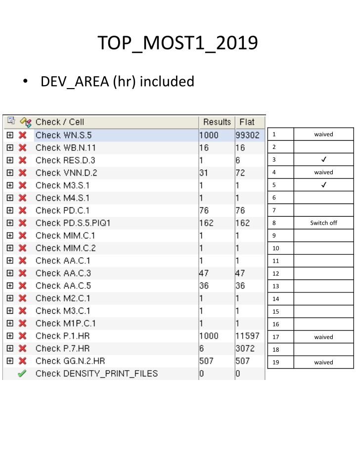
TOP_MOST1_2019 DEV_AREA (hr) included 1 waived 2 3 4 waived 5 6 7 8 Switch off 9 10 11 12 13 14 15 16 17 waived 18 19 waived
WN.S.5 WN.S.5:For Image sensor using Epi process only: Space between two WN s having different potential. DRC will check this rule if EPI flag is invoked in the runset , must be min 2.8 um, for Different net ( WN.S.5 - Nodal Check ) . WN.S.5 : in the past, we already waved this rules inside the pixels with a distance between two WN of 1.4 m. Gregory WN.S.3 WN.S.3 Space between two WN s having different potentials. That is: 1.8V ~ 1.8V, 3.3V ~ 3.3V , 1.8V ~ 3.3V ,1.8V ~ 4.1V or 4.1V ~ 4.1V min 1.4 Error P P P Diode P Waived
WB.N.11 WB.N.11: VNN interacting with WB is not allowed. WB.N.11 -> must be fixed. Gregory Error AoutBuffer DAC BGP_npn RSDS LVDS PeripheralReadout VNN 0.005um
VNN.D.2 VNN.D.2: Distance from VNN outside WN to WN Edge, min 1.66. VNN.D.2 -> could be waived. Gregory Error AoutBuffer LVDS PeripheralReadout DAC BGP_npn RSDS APAD_IO Waived
PD.C.1 PD.C.1: VIA Density Inside PAD, min 0.05 (This Rule is Not applicable for Dummy Pads). VNN.D.2 -> must be fixed. Gregory Error DIGITAL_IO_Pullup DIGITAL_IO_Pulldown V3
PD.S.5.PIQ1 PD.S.5.PIQ1:For PIQ1: PAD-to-pad space, min 33. I don't have this PD.S.5.PIQ1 on my DRC or in my design rules. But our PDK is quite old (from January 2018) and I will update it before the submission. Gregory Error PAD(drw) PAD(drw) space 26.91 PAD 93.09 87um Check Selection Recipe
P.1.HR P.1.HR: WPD (Deep P-Well) must cover the whole CMOS Area, excluding: * Deep N-Wells (WB) A fixed distance of 1 [um] between WPD to any WB must be kept * Pixel ARRAY_AREA (80dt72) * Pixel Array N-Well Guard Ring (77dt106) Could be waived. (Gregory) Error PAD WP pick-up WP pick-up Waived. Layout
P.7.HR P.7.HR: Space between VSS (ground) taps inside ARRAY_AREA, Max 15. P7.HR : -> should be fixed . (Gregory) Error . WP pick-up
GG.N.2.HR GG.N.2.HR: WPD(lc) in the area enclosed by DEV_AREA(gg), or WPD interacting with DEV_AREA(gg) is not allowed GG.N.2.HR -> could be waived (WPD put inside pixel array). (Gregory) Error PMOS WPD Waived.
MIM.C.1/2 MIM.C.1: Coverage of CE area on overall chip area ,min 0.03 MIM.C.2: For stacked MIM: Coverage of BCE area on overall chip area Note that BCE is generated from CE and SPC_AREA(mm) in stacked MIM capacitors ,min 0.03 Error BGP_npn cmim_hc OTA cmim_stk Must be fixed.
AA.C.1/3/5 AA.C.1: Sized AA density also inside NODUMMY region, should be min 0.15 , for Window of 200X200 microns ( AA.C.1 ). AA.C.3: Sized AA density also inside NODUMMY region, should be min 0.20 , for Window of 100X100 microns ( AA.C.3 ). Except where spacing is smaller than 8 Microns. AA.C.5: Sized AA density also inside NODUMMY region, should be min 0.30 , for Window of 100X100 microns ( AA.C.5 ). Except where spacing is smaller than 20 Microns. Error AA Must be fixed.
M1P.C.1 M1P Layer (Optional for Pixel Array) M1P is M1;lc covered by M1;is and is located at ARRAY_AREA only M1P.C.1: Coverage of M1 total chip area. For DRC purposes, coverage is calculated by [(M1(lc)+M1(dy)-M1(ms)]/(chip area). This rule is not checked under embedded IP area , Min 30% M1.C.1 Min 20%. Error M1 Must be fixed. dummy
MI.C.1 MI.C.1: MI Coverage less than 0.20 ( MI.C.1 ). Error M2/M3 M2/M3.C.1 Must be fixed.
CHIP2 DEV_AREA (hr) not included 1 2 3 4 5 6 7 8 9 10 11 12
