Electric Machinery Fundamentals

ELECTRIC Machines II
Prof.Dr. Karthikeyan C Balasundaram
Room: 3
rd
Floor, University Block
Mob: +255 22 62 11 42 42 2
Email: director_pgrs@sjuit.ac.tz
Basic electricity/ Current (I):
Electricity is the flow of electrons from one place to another. Electrons
can flow through any material, but does so more easily in some than in others.
...
Neutral Atom:
A
neutral atom
is an
atom
where the charges of the electrons and the protons
balance
Charge of electron=charge of proton
ION
When an
atom
is attracted to another
atom
because it has an unequal number
of
electrons
and
protons
, the
atom
is called an
ION
.
If the
atom
has more
electrons
than
protons
, it is a
negative ion
, or
ANION
.
If it has more
protons
than
electrons
,it is a
positive ion or Cation
Terminologies…
P
o
t
e
n
t
i
a
l
D
i
f
f
e
r
e
n
c
e
(
V
o
l
t
a
g
e
)
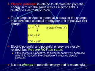
The electrical
potential difference
is defined as the amount of work
done to carrying a unit charge from one point to another in an electric
field. In other words, the
potential difference
is defined as
the
difference
in the electric
potential
of the two charged bodies
Conductor/Semiconductor/Insulator
The main
difference …
is in its conduction state.
The
conductors
always conduct electric current
while the
insulators
do no conduct.
However,
semiconductor
conducts & blocks at different conditions.
LAWS/RULE…
•
OHMS LAW
•
KICHOFFS CURRENT LAW
•
KIRCHOFFS VOLTAGE LAW
•
FARADAY LAW
•
FLEMMINGS LEFT HAND RULE
•
FLEMMINGS RIGHT HAND RULE
•
CORK SCREW RULE
•
LENZ LAW
Ohms law
•
At constant temperature, the current through an
ideal
resistor
(Resistivity?)
is directly proportional to the voltage applied
across the resistor
•
Why the temperature is kept constant in Ohm’s law
•
The
limitations of Ohm’s law
:
•
This law cannot be applied to unilateral networks.
A unilateral network has unilateral elements like
diode
,
transistors
, etc., which
do not have same
voltage
current relation for both directions of current.
•
Ohm’s law
is also not applicable for non – linear elements.
Non-linear elements are those which do not have
current
exactly proportional
to the applied
voltage
, that means the
resistance
value of those elements
changes for different values of voltage and
current
.
Examples of non – linear elements are
thyristor
, diode.. etc.
Kirchhoff's current/voltage laws
Faraday laws
Faraday laws of electromagnetic induction is a basic law of
electromagnetism predicting how a magnetic field wil interact with an
electric field to produce electromagnetic force. This phenomenon is called
electromagnetic induction.
First Law: Whenever a conductor is placed in changing magnetic field an
emf is inducd and if the conductor path is closed, an induced current flows
through it.
Second Law:
The induced emf is equal to the Change of Flux Linkage (Flux linkage os the
product of turns (n) and the flux associated with it
Explanation for better understanding
•
Let the initial flux linkagebe = Nɸ1
Final flux linkage - Nɸ2
Change n flux linkage: Nɸ2-Nɸ1 = N(ɸ2-ɸ1) = Nɸ
Rate of Change in Flux Linkage= Nɸ/t wb/sec
Taking Derivative on Right Hand Side (RHS)
Rate of Change in Flux Linkage= N dɸ/dt wb/sec
As per faraday law induced emf E= rate of change in flux linkage
Hence e= N dɸ/dt volts =
-
N dɸ/dt , where the negative sign indicates
the direction of induced current
Cycle
•
Cycle
One complete set of positive and negative values of alternating quantity
is known as cycle.
A cycle may also be sometimes specified in terms of angular measure.
In that case, one completecycle is said to spread over 360º or 2π radians.
Time Period
•
The time taken by an alternating quantity to complete one cycle is
called its time period
T
. For example, a 50-Hz alternating current has a
time period of 1/50 second.
•
f
= 1/
T
or
T
= 1/
f
Frequency
•
The number of cycles/second is called the frequency of the alternating
quantity. Its unit is hertz (Hz).
•
Amplitude
•
The maximum value, positive or negative, of an alternating quantity is
known as its amplitude.
•
Different Forms of E.M.F. Equation
•
The standard form of an alternating voltage, is
e
=
Em
sin θ =
Em
sin ω
t
=
Em
sin 2 π
f t
=
Em
sin (2
π
/T) x
t
•
By closely looking at the above equations, we find that
(
i
)
the maximum value or peak value or amplitude of an
alternating
voltage is given by thecoefficient of the sine of the time angle.
(
ii
)
the frequency f is given by the coefficient of time divided by 2
π
..
P
h
a
s
e
D
i
f
f
e
r
e
n
c
e
phasedifference between
A
and
B
is β and between
B
and
C
is α but between
A
and
C
is (α + β). The
statement, however, does not give indication as to
which e.m.f. reaches its maximum value first. This
deficiency is supplied by using the terms
‘
lag
’
or
‘
lead
’.
Root-Mean-Square (R.M.S.) Value
•
The r.m.s. value of an alternating current
is given by that steady (d.c.)
current which whenflowing through a given circuit for a given time
produces the same
heat
as produced by the alternating current when
flowing through the same circuit for the same time
.
Average Value
•
The average value
Ia
of an alternating current is expressed
by that
steady current which transfers across any circuit the same charge as
is transferred by that alternating current during the same time.
Form factor and Peak factor
Multiples and Sub-multiples
Power…
Lumped Circuit…
•
A
lumped circuit
is a
circuit
where electrical parameters (R, L, C) are
assumed to be concentrated at one place
T
H
U
M
B
R
U
L
E
S
…
•
For Cu Wire, Current Capacity (Up to 30 Sq.mm) =
6X Size of Wire
in Sq.m
•
Ex. For 2.5 Sq.mm=6×2.5=15 Amp,
•
For 1 Sq.mm=6×1=6 Amp,
•
For 1.5 Sq.mm=6×1.5=9 Amp
•
For Cable, Current Capacity =
4X Size of Cable in Sq.mm ,
•
Ex. For 2.5 Sq.mm=4×2.5=9 Amp.
•
Current Capacity of Equipments:
•
1 Phase Motor draws Current=
7 Amp per HP.
•
3 Phase Motor draws Current=
1.25 Amp per HP.
•
Full Load Current of 3 Phase Motor=
HPx1.5
•
Full Load Current of 1 Phase Motor=
HPx6
•
Current Rating of Transformer
=KVAx1.4
Essential concepts in electric machinery including basic electricity, current flow, potential difference, Ohm's Law, Kirchhoff's laws, Faraday's laws, and more. Gain insights into terminologies, conductors, and insulators to enhance your understanding and application of electric machinery principles.

Download Presentation

Please find below an Image/Link to download the presentation.
The content on the website is provided AS IS for your information and personal use only. It may not be sold, licensed, or shared on other websites without obtaining consent from the author.If you encounter any issues during the download, it is possible that the publisher has removed the file from their server.
You are allowed to download the files provided on this website for personal or commercial use, subject to the condition that they are used lawfully. All files are the property of their respective owners.
The content on the website is provided AS IS for your information and personal use only. It may not be sold, licensed, or shared on other websites without obtaining consent from the author.
E N D
Presentation Transcript
ELECTRIC Machines II Prof.Dr. Karthikeyan C Balasundaram Room: 3rdFloor, University Block Mob: +255 22 62 11 42 42 2 Email: director_pgrs@sjuit.ac.tz
Terminologies Basic electricity/ Current (I): Electricity is the flow of electrons from one place to another. Electrons can flow through any material, but does so more easily in some than in others. ... Neutral Atom: Aneutral atom is an atom where the charges of the electrons and the protons balance Charge of electron=charge of proton ION When an atom is attracted to another atom because it has an unequal number of electrons and protons, the atom is called an ION. If the atom has more electrons than protons, it is a negative ion, or ANION. If it has more protons than electrons,it is a positive ion or Cation
Potential Difference(Voltage) Potential Difference(Voltage) The electrical potential difference is defined as the amount of work done to carrying a unit charge from one point to another in an electric field. In other words, the potential difference is defined as the difference in the electric potential of the two charged bodies Conductor/Semiconductor/Insulator The main difference is in its conduction state. The conductors always conduct electric current while the insulators do no conduct. However, semiconductor conducts & blocks at different conditions.
LAWS/RULE OHMS LAW KICHOFFS CURRENT LAW KIRCHOFFS VOLTAGE LAW FARADAY LAW FLEMMINGS LEFT HAND RULE FLEMMINGS RIGHT HAND RULE CORK SCREW RULE LENZ LAW
Ohms law At constant temperature, the current through an ideal resistor(Resistivity?) is directly proportional to the voltage applied across the resistor Why the temperature is kept constant in Ohm s law The limitations of Ohm s law : This law cannot be applied to unilateral networks. A unilateral network has unilateral elements like diode, transistors, etc., which do not have same voltage current relation for both directions of current. Ohm s law is also not applicable for non linear elements. Non-linear elements are those which do not have current exactly proportional to the applied voltage, that means the resistance value of those elements changes for different values of voltage and current. Examples of non linear elements are thyristor, diode.. etc.
Faraday laws Faraday laws of electromagnetic induction is a basic law of electromagnetism predicting how a magnetic field wil interact with an electric field to produce electromagnetic force. This phenomenon is called electromagnetic induction. First Law: Whenever a conductor is placed in changing magnetic field an emf is inducd and if the conductor path is closed, an induced current flows through it. Second Law: The induced emf is equal to the Change of Flux Linkage (Flux linkage os the product of turns (n) and the flux associated with it
Explanation for better understanding Let the initial flux linkagebe = N 1 Final flux linkage - N 2 Change n flux linkage: N 2-N 1 = N( 2- 1) = N Rate of Change in Flux Linkage= N /t wb/sec Taking Derivative on Right Hand Side (RHS) Rate of Change in Flux Linkage= N d /dt wb/sec As per faraday law induced emf E= rate of change in flux linkage Hence e= N d /dt volts = -N d /dt , where the negative sign indicates the direction of induced current
Cycle Cycle One complete set of positive and negative values of alternating quantity is known as cycle. A cycle may also be sometimes specified in terms of angular measure. In that case, one completecycle is said to spread over 360 or 2 radians.
Time Period The time taken by an alternating quantity to complete one cycle is called its time period T. For example, a 50-Hz alternating current has a time period of 1/50 second. f = 1/T or T = 1/f
Frequency The number of cycles/second is called the frequency of the alternating quantity. Its unit is hertz (Hz).
Amplitude The maximum value, positive or negative, of an alternating quantity is known as its amplitude.
Different Forms of E.M.F. Equation The standard form of an alternating voltage, is e = Em sin = Em sin t = Em sin 2 f t = Em sin (2 /T) x t By closely looking at the above equations, we find that (i) the maximum value or peak value or amplitude of an alternating voltage is given by thecoefficient of the sine of the time angle. (ii) the frequency f is given by the coefficient of time divided by 2 ..
Phase Difference Phase Difference phasedifference between A and B is and between B and C is but between A and C is ( + ). The statement, however, does not give indication as to which e.m.f. reaches its maximum value first. This deficiency is supplied by using the terms lag or lead .
Root-Mean-Square (R.M.S.) Value The r.m.s. value of an alternating current is given by that steady (d.c.) current which whenflowing through a given circuit for a given time produces the same heat as produced by the alternating current when flowing through the same circuit for the same time.
Average Value The average value Ia of an alternating current is expressed by that steady current which transfers across any circuit the same charge as is transferred by that alternating current during the same time.
Electrical Parameter Measuring Unit Symbol Description Unit of Electrical Potential V = I R Voltage Volt V or E Unit of Electrical Current I = V R Current Ampere I or i Unit of DC Resistance R = V I Resistance Ohm R or Reciprocal of Resistance G = 1 R G or Conductance Siemen Unit of Capacitance C = Q V Capacitance Farad C Unit of Electrical Charge Q = C V Charge Coulomb Q Unit of Inductance VL= -L(di/dt) Inductance Henry L or H Unit of Power P = V I or I2 R Power Watts W Unit of AC Resistance Z2= R2+ X2 Impedance Ohm Z Unit of Frequency = 1 T Frequency Hertz Hz
Lumped Circuit Alumped circuit is a circuit where electrical parameters (R, L, C) are assumed to be concentrated at one place
THUMB RULES THUMB RULES For Cu Wire, Current Capacity (Up to 30 Sq.mm) = 6X Size of Wire in Sq.m Ex. For 2.5 Sq.mm=6 2.5=15 Amp, For 1 Sq.mm=6 1=6 Amp, For 1.5 Sq.mm=6 1.5=9 Amp For Cable, Current Capacity =4X Size of Cable in Sq.mm , Ex. For 2.5 Sq.mm=4 2.5=9 Amp. Current Capacity of Equipments: 1 Phase Motor draws Current=7 Amp per HP. 3 Phase Motor draws Current=1.25 Amp per HP. Full Load Current of 3 Phase Motor=HPx1.5 Full Load Current of 1 Phase Motor=HPx6 Current Rating of Transformer=KVAx1.4


")


 Value")