DOM Acceptance and Calibration Plan Overview
This comprehensive plan outlines the acceptance and calibration processes for Deployed Optical Modules (DOMs) across multiple sites. It includes detailed instructions for assembly, testing, and calibration procedures involving sophisticated instrumentation and time-sensitive tasks. The plan covers integration, measurement details, parameters to be saved, and VEOC-DOM specifications, ensuring thorough quality control and accurate data collection.
Download Presentation

Please find below an Image/Link to download the presentation.
The content on the website is provided AS IS for your information and personal use only. It may not be sold, licensed, or shared on other websites without obtaining consent from the author.If you encounter any issues during the download, it is possible that the publisher has removed the file from their server.
You are allowed to download the files provided on this website for personal or commercial use, subject to the condition that they are used lawfully. All files are the property of their respective owners.
The content on the website is provided AS IS for your information and personal use only. It may not be sold, licensed, or shared on other websites without obtaining consent from the author.
E N D
Presentation Transcript
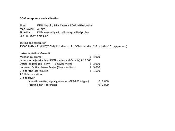
DOM acceptance and calibration Sites: Man Power: Time Plan: See PRR DOM time plan Testing and calibration 15000 PMTs / 31 (PMT/DOM) in 4 sites = 121 DOMs per site 6 months (20 days/month) INFN Napoli , INFN Catania, ECAP, Nikhef, other All site DOM Assembly with all pre-qualified probes Instrumentation: Green Box Mechanical Frame Laser source (available at INFN Naples and Catania) 15.000 Optical splitter 1x4 : 5 PMT + 1 power meter Improved Optical Power Meter (fibre monitor) UPS for the laser source 1 full shore station GPS receiver acoustic emitter, signal generator (GPS-PPS trigger) rotating dish + reference 4.000 3.000 5.000 1.500 2.000 2.000
Measurements and time details: DOM integration Gel solidification 12 h 12 h Green box closing and pre-setting Set Gain (PMT on at Nominal HV for pulse mode operation) Recover correspondance of number of PMT/base and mounting position from the Database Wait conditiong of PMTs 30 min 1 h Functioning test of the DOM using laser source 30 min Wait or not 8 h? depending on integration schedule A:Dark Current Rate (with glass and gel) Dark rate on all PMTs verify the specs of the PMT (if not long dark adaption observe only large deviations of few PMts) Mapping and relative time calibration using 40 K coninc (see http://pi1222.physik.uni-erlangen.de/Qualification/24) TOT check using single photo-electrons from 40K B: Laser calibration (absolute) 4 reference PMTs (far one from the other) - Laser triggered by GPS and amplitude set to 10 spe and 20 kHz Check absolute time on reference PMTs (TT or delta-T) Check relative to absolute time for PMTs close to the fiber Redo mapping and check with previous one C:Functionality test of nano beacon maximum amplitude @ 20 kHz minimum amplitude @ 20 kHz Check the nanobeacon functionality Redo mapping for PMTs close to the nano-beacon and check with previous ones D: Functionality test of acoustic reception (20,30,40 kHz, 2 amplitudes, acoustic emitter trigger GPS-PPS) Check functionality of the piezo rough estimate to sensitivity to different frequencies and measure of noise check time correlation signal master clock D:Compass Calibration using rotating dish readout of AHRS > 1Hz, PC with RS232 to drive the step motor encoder store compass data and AHRS data recover the AHRS calibration matrixes DOM Packing 10 min 2 min 5 min 5 min 15 min 20 min
Parameters to be saved: Histo coincidences for mapping (to be defined) Mapping matrix + indication on PMT (green, yellow, red) TOT (@ spe) green box (histo, mean, sigma fit, or RMS) Dark rate (specifying dark adaption time) Histo TOT (dark rate counts) 31 Histo Delta-T (TtT)
VEOC-DOM: extra length for 1 complete 360 turn Base used also for assembly Holder Holder Acoustic emitter Rotating dish (encoded motor below)
Soft flange For VEOC-DOM Optical splitter for time calibration
Soft flange For VEOC-DOM Optical splitter for time calibration Holder Holder Acoustic emitter Rotating Dish Encoded motor below)
