Direct-Injection Constant-Volume Combustion Chamber for Chemical Kinetic Modeling
Demonstrating a direct-injection constant-
volume combustion chamber as a validation tool
for chemical kinetic modeling of liquid fuels
Aaron Suttle
1
, Brian Fisher
2
, Dennis Parnell
1
, and
Joshua Bittle
1
1
The University of Alabama,
2
Naval Research Laboratory
ASME 2018 Internal Combustion Engine
Fall Technical Conference
San Diego, CA
1/17
Presentation Overview
2/17
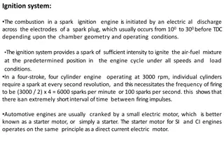
•
Ignition Research Techniques
•
Background Motivation
•
Experimental Setup and Modifications
•
Data Processing and Test Plan
•
Results
•
Summary and Future work
Ignition Research Techniques
3/17
•
Computationally based combustion research utilizes
chemical-kinetic mechanisms to model the complex
chemical reactions and the combustion phenomena
•
Experimentally based studies use a variety of devices:
–
Rapid Compression Machines (RCM)
–
Shock Tubes
–
Constant Volume Combustion Chambers (CVCC)-The ignition
quality tester (IQT) and derived cetane tester (CID)
•
Combustion occurring within each of these devices is then
captured via combustion pressure transducers or optical
ports
•
In order to facilitate mechanism development, each
system would be approximated as a perfect stirred reactor
Ignition Research
Techniques - CVCC
4/17
When using a CVCC considerations must be made, which form
limitations on the device’s capabilities
1.
Due to the transient nature of the fuel injection process,
there exists a time below which, the chamber cannot be
considered “well mixed”
2.
Accurate measurement of thermodynamic state of
contained air mass for estimation of initial conditions and
global equivalence ratio is critical
3.
Accurate characterization and control of the fuel injection
system is of utmost importance for limiting uncertainty
associated with the fuel injection process
Project Motivation and Background
5/17
•
Combustion of liquid fuels is often
studied for the validation or
refinement of chemical-kinetic
mechanisms
•
A particular difficulty for traditional
combustion test apparatuses are
low volatility fuels
•
These fuels can be difficult to
evaporate, and maintain in a vapor
state prior to mixing with air and
increasing mixture temperature
•
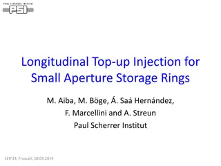
The Derived Cetane Tester (CID 510)
addresses this by injecting liquid fuel
into a heated, high pressure
constant volume combustion
chamber by utilizing a commercial
diesel engine injector
High
Pressure
Fuel
Supply and
Transducer
Combustion
Chamber
Injector
Gas Supply
Combustion
Pressure
Transducer
Experimental Setup and Modifications
6/17
•
Beginning with the unmodified CID, an external control and DAQ
system was developed to expand the chambers range of testable
temperatures, pressures, and equivalence ratios
Device Characterization
7/17
After completing expansion of the CID controls, the various
processes related to the device’s accuracy were characterized
These included:
•
Chamber wall temperature offset and temperature spatial
homogeneity
•
Volume of injected fuel calibration
•
Effects of evaporative cooling
•
Calibration of all onboard pressure transducers
Device Characterization
8/17
Test Plan and Data Processing
9/17
Initial Results –
φ
,T sweeps
10/17
n
-heptane – P
amb
= 5 bar
iso-octane – P
amb
= 20 bar
Based on confidence in thermodynamic state and injection durations, a
minimum threshold ignition delay of 10 ms results in a kinetics dominated
ignition event that can reasonably be compared to a 0-D model.
Initial Results
– φ,
T sweeps
Why would
n
-heptane have
better agreement with model
than iso-octane at nominally
same ignition delay range?
Next step:
–
try to study pressure effects
–
Must use iso-octane due to
τ
ign
range
11/17
n
-heptane – P
amb
= 5 bar
iso-octane – P
amb
= 20 bar
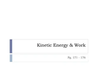
Octane Pressure Sweep
•
Relative pressure effects
are captured
•
Extremes of NTC region
are not and only low P
cases show reversal in
τ
ign
•
Capturing pressure
dependence is a focus of
kinetic model developers.
•
In this case the
dependence is over
predicted.
12/17
Bulk Temperature Histories
•
Process pressure histories
into bulk temperature
assuming ideal gas and
constant gas constant*
•
Plotted range of 600-1200 K
highlights low-temp. regime
•
Apparent low-temp kinetics
barrier around 800 K.
•
Correlation between temp.
increase during 1
st
stage
and secondary delay to
main ignition.
13/17
iso-octane – P
amb
= 5 bar
*during the 1
st
stage reactions the bulk gas constant does not change much and will not affect trends.
Bulk Temperature Histories
•
Same observations, except no
reversal in main ignition delay
trend.
•
Apparent low-temp kinetics
barrier around 825 K in this
case.
•
This barrier tends to slow the
overall ignition process for
temperatures in the NTC region.
•
For T
amb
>850 K, 1
st
stage begins
before 10 ms threshold.
14/17
iso-octane – P
amb
= 15 bar
*during the 1
st
stage reactions the bulk gas constant does not change much and will not affect trends.
Connection of 1
st
to 2
nd
Delay
•
Results suggest concentrations of
main ignition precursors (e.g.
H
2
O
2
) after 1
st
stage is proportional
with 1
st
statge heat release (
α
Δ
T)
•
Increase in initial temp reduces 1
st
stage HR and thus more time is
needed for accumulation of
precursors before main ignition.
•
Above the kinetic barrier, 1
st
stage
kinetics still present, but precursor
accumulation is primarily through
other pathways.
15/17
iso-octane
Comparison With Other Devices Work
16/17
While not included in paper, the key difference is that
CID, IQT, RCM all show suppressed NTC behavior
compared to model and shock tubes.
Summary and Conclusions
17/17
•
The modified CID is a capable ignition delay test
apparatus based on extensive characterization of
thermodynamic state.
•
Under conditions with more than 10 ms ignition delay the
results may be reasonably compared to 0-D simulations.
•
Temperature profiles highlight interesting NTC behavior
and illustrate low-temperature kinetic barriers.
•
Comparing CID and other apparatus to models suggest
over prediction of sensitivity to pressure (at least in
context of internal combustion engines).
Thank you for your
attention!
18
Chamber Temperature Offset
19/17
•
Chamber temperature offset was measured at 9 temperature
and pressure conditions
•
The plot below was used to curve fit a surface equation for the
purpose of estimating total wall temperature offset
This study validates chemical kinetic models of liquid fuels using a direct-injection constant-volume combustion chamber. The research explores ignition research techniques, experimental setups, and data processing for mechanism development. Project motivation focuses on studying combustion of low volatility fuels and improving understanding of combustion phenomena. Advanced devices like the Derived Cetane Tester are utilized to address challenges in fuel injection processes and mixture temperature control.

Download Presentation

Please find below an Image/Link to download the presentation.
The content on the website is provided AS IS for your information and personal use only. It may not be sold, licensed, or shared on other websites without obtaining consent from the author. Download presentation by click this link. If you encounter any issues during the download, it is possible that the publisher has removed the file from their server.
E N D
Presentation Transcript
Demonstrating a direct-injection constant- volume combustion chamber as a validation tool for chemical kinetic modeling of liquid fuels Aaron Suttle1, Brian Fisher2, Dennis Parnell1, and Joshua Bittle1 1The University of Alabama, 2Naval Research Laboratory ASME 2018 Internal Combustion Engine Fall Technical Conference San Diego, CA 1/17
Presentation Overview Ignition Research Techniques Background Motivation Experimental Setup and Modifications Data Processing and Test Plan Results Summary and Future work 2/17
Ignition Research Techniques Computationally based combustion research utilizes chemical-kinetic mechanisms to model the complex chemical reactions and the combustion phenomena Experimentally based studies use a variety of devices: Rapid Compression Machines (RCM) Shock Tubes Constant Volume Combustion Chambers (CVCC)-The ignition quality tester (IQT) and derived cetane tester (CID) Combustion occurring within each of these devices is then captured via combustion pressure transducers or optical ports In order to facilitate mechanism development, each system would be approximated as a perfect stirred reactor 3/17
Ignition Research Techniques - CVCC When using a CVCC considerations must be made, which form limitations on the device s capabilities 1. Due to the transient nature of the fuel injection process, there exists a time below which, the chamber cannot be considered well mixed 2. Accurate measurement of thermodynamic state of contained air mass for estimation of initial conditions and global equivalence ratio is critical 3. Accurate characterization and control of the fuel injection system is of utmost importance for limiting uncertainty associated with the fuel injection process 4/17
Project Motivation and Background Combustion of liquid fuels is often studied for the validation or refinement of chemical-kinetic mechanisms A particular difficulty for traditional combustion test apparatuses are low volatility fuels These fuels can be difficult to evaporate, and maintain in a vapor state prior to mixing with air and increasing mixture temperature The Derived Cetane Tester (CID 510) addresses this by injecting liquid fuel into a heated, high pressure constant volume combustion chamber by utilizing a commercial diesel engine injector High Pressure Fuel Supply and Transducer Injector Combustion Chamber Combustion Pressure Transducer Gas Supply 5/17
Experimental Setup and Modifications Beginning with the unmodified CID, an external control and DAQ system was developed to expand the chambers range of testable temperatures, pressures, and equivalence ratios 6/17
Device Characterization After completing expansion of the CID controls, the various processes related to the device s accuracy were characterized These included: Chamber wall temperature offset and temperature spatial homogeneity Volume of injected fuel calibration Effects of evaporative cooling Calibration of all onboard pressure transducers 7/17
Initial Results ,T sweeps n-heptane Pamb = 5 bar iso-octane Pamb = 20 bar Based on confidence in thermodynamic state and injection durations, a minimum threshold ignition delay of 10 ms results in a kinetics dominated ignition event that can reasonably be compared to a 0-D model. 10/17
Initial Results ,T sweeps Why would n-heptane have better agreement with model than iso-octane at nominally same ignition delay range? n-heptane Pamb = 5 bar iso-octane Pamb = 20 bar Next step: try to study pressure effects Must use iso-octane due to ign range 11/17
Octane Pressure Sweep Relative pressure effects are captured Extremes of NTC region are not and only low P cases show reversal in ign Capturing pressure dependence is a focus of kinetic model developers. In this case the dependence is over predicted. 12/17
Bulk Temperature Histories iso-octane Pamb = 5 bar Process pressure histories into bulk temperature assuming ideal gas and constant gas constant* Plotted range of 600-1200 K highlights low-temp. regime Apparent low-temp kinetics barrier around 800 K. Correlation between temp. increase during 1st stage and secondary delay to main ignition. *during the 1st stage reactions the bulk gas constant does not change much and will not affect trends. 13/17
Bulk Temperature Histories iso-octane Pamb = 15 bar Same observations, except no reversal in main ignition delay trend. Apparent low-temp kinetics barrier around 825 K in this case. This barrier tends to slow the overall ignition process for temperatures in the NTC region. For Tamb>850 K, 1st stage begins before 10 ms threshold. *during the 1st stage reactions the bulk gas constant does not change much and will not affect trends. 14/17
Connection of 1st to 2nd Delay iso-octane Results suggest concentrations of main ignition precursors (e.g. H2O2) after 1st stage is proportional with 1st statge heat release ( T) Increase in initial temp reduces 1st stage HR and thus more time is needed for accumulation of precursors before main ignition. Above the kinetic barrier, 1st stage kinetics still present, but precursor accumulation is primarily through other pathways. 15/17
Comparison With Other Devices Work While not included in paper, the key difference is that CID, IQT, RCM all show suppressed NTC behavior compared to model and shock tubes. n-heptane 3-4.5 bar CID to RCM iso-octane 15 bar CID to shocktube 16/17
Summary and Conclusions The modified CID is a capable ignition delay test apparatus based on extensive characterization of thermodynamic state. Under conditions with more than 10 ms ignition delay the results may be reasonably compared to 0-D simulations. Temperature profiles highlight interesting NTC behavior and illustrate low-temperature kinetic barriers. Comparing CID and other apparatus to models suggest over prediction of sensitivity to pressure (at least in context of internal combustion engines). 17/17
Thank you for your attention! 18
Chamber Temperature Offset Chamber temperature offset was measured at 9 temperature and pressure conditions The plot below was used to curve fit a surface equation for the purpose of estimating total wall temperature offset 19/17