Diode Circuits and Rectifiers for Power Supplies

 undefined


Chapter-V
Diode Circuits:
Series and parallel diode circuits, Clippers, Clampers,
Voltage multipliers.
Power Supplies:
Half-wave and full wave rectifiers,
Derivation of Vrms, Vdc, ripple factor, peak inverse voltage,
rectification efficiency in each case
Capacitor filter.
Working and design of a simple zener voltage
regulator.
Block diagram description of a DC Power supply.
Principle of SMPS
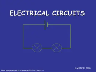
Used for converting AC to DC.
Two types.
Half wave rectifier-
Getting output in the half cycle of
the input signal.
Full wave rectifier-
Getting output in the full cycle of
the input signal.
Peak Inverse Voltage (PIV)
Maximum voltage the diode must withstand during
the reverse bias half cycle of the input signal.
PIV in HWR = Vm
Disadvantages:
Low output because only one half cycle delivers the
output.
AC components are more in the output.
DC Output
The DC output voltage or a current of the rectifier is the average value of the
output voltage or current.
RMS Value
Ripple Factor
Efficiency
In a half wave rectifier the load resistance RL=1KΩ the forward resistance of the diode
rd=100Ω, input alternating voltage (Vm) =325 volt. Find (a) Peak value, average value
and rms value of the output current (b) Efficiency of the rectifier.
Full wave rectifiers are of two types,
Centre tap rectifier
Bridge rectifier
PIV = 2Vm
PIV= Vm
The purpose of the rectifier is to convert AC voltage
to DC. But not type of rectifier converts AC to pure
DC. It produces pulsating DC. This residual pulsation
is called ripple.
Ripple factor indicates the effectiveness of the
rectifier in converting AC to perfect DC. It is the
ratio of the ripple voltage to the DC voltage.
For HWR , γ =1.21
For FWR, γ = .482
Efficiency of the rectifier is a measure of
conversion of AC power to the useful DC output
power. It is expressed as the ratio of DC output
power to AC input power.
For HWR, η = 40.6 %
For FWR, η= 81.2 %
In a full wave centre tap rectifier, the load resistance used is of 2KΩ,the forward resistance of
each diode is 400Ω,the voltage across the half of the secondary winding is 240 Sin50t.Find (a)
I
m
, (b)
I
dc
(c) I
rms
(d) ripple factor (e) PIV.
Parameters used to measure the performance of
voltage regulator are
line regulation
and
load regulation.
Line regulation
is the ratio of change in output voltage
to the change in source voltage.
Load regulation
is defined as the ratio of change in
output voltage to the change in load current.
Basic Concept
U
ses a series switching element that turns the current supply to a
smoothing capacitor on and off.
The time the series element is turned on is controlled by the voltage on the capacitor. If it is
higher than required, the series switching element is turned off, if it is lower than required,
it is turned on. In this way the voltage on the smoothing or reservoir capacitor is maintained
at the required level.
Advantages
High efficiency
Compact
Flexible technology
Disadvnatages
Noise
Expert Design Required
Costly
Clippers
Clampers
Multipliers
Series Negative Clipper
Series Positive Clipper
Biased Series Negative Clipper
Biased Series Positive Clipper
Positive Clipper
Negative Clipper
Biased Positive clipper with Positive supply
Biased Negative clipper with Negative supply
The
clamping
network is one that will “clamp”
a signal to a different dc level.
Clamping circuits are often used in TV
receivers as dc restorers.
Clamper Types
Positive Clamper
Negative Clamper
Biased positive Clamper
Biased Negative Clamper
V
o
= V
m
+V
m
sin
t.
V
o
= -V
m
+V
m
sin
t
Vo= (V
m
+3)+ V
m
sin
t.
Vo= -V
m
-3+ V
m
sin
t = -(V
m
+3)+ V
m
sin
t
.
Voltage multipliers are AC-to-DC power conversion
devices, comprised of diodes and capacitors, that
produce a high potential DC voltage from a lower
voltage AC source.
Generally, the DC output voltage (V
dc
) of a rectifier
circuit is limited by the peak value of its sinusoidal
input voltage. But by using combinations of
rectifier diodes and capacitors together we can
effectively multiply this input peak voltage to give a
DC output equal to some odd or even multiple of
the peak voltage value of the AC input voltage.
Exploring the functionality of diode circuits in series and parallel configurations, along with clippers, clampers, and voltage multipliers. Gain insights into power supplies such as half-wave and full-wave rectifiers, Vrms derivation, Ripple Factor, and more. Learn about diode behavior in rectification, the concept of Peak Inverse Voltage (PIV), DC output characteristics, RMS value, Ripple Factor, and efficiency calculations. Dive into the design and operation of simple zener voltage regulators and DC power supplies.

Download Presentation

Please find below an Image/Link to download the presentation.
The content on the website is provided AS IS for your information and personal use only. It may not be sold, licensed, or shared on other websites without obtaining consent from the author.If you encounter any issues during the download, it is possible that the publisher has removed the file from their server.
You are allowed to download the files provided on this website for personal or commercial use, subject to the condition that they are used lawfully. All files are the property of their respective owners.
The content on the website is provided AS IS for your information and personal use only. It may not be sold, licensed, or shared on other websites without obtaining consent from the author.
E N D
Presentation Transcript
DiodeCircuits: Series and parallel diode circuits, Clippers, Clampers, Voltage multipliers. PowerSupplies: Half-wave and full wave rectifiers, Derivation of Vrms,Vdc, ripple factor, peakinverse voltage, rectificationefficiencyin eachcase Capacitorfilter. Working and design of a simple zener voltage regulator. Block diagram descriptionof a DCPower supply. PrincipleofSMPS
Used for converting AC to DC. Two types. Half wave rectifier-Getting output in the half cycle of the input signal. Full wave rectifier-Getting output in the full cycle of the input signal.
Peak Inverse Voltage (PIV) Maximum voltage the diode must withstand during the reverse bias half cycle of the input signal. PIV in HWR = Vm Disadvantages: Low output because only one half cycle delivers the output. AC components are more in the output.
DC Output The DC output voltage or a current of the rectifier is the average value of the output voltage or current.
In a half wave rectifier the load resistance RL=1K the forward resistance of the diode rd=100 , input alternating voltage (Vm) =325 volt. Find (a) Peak value, average value and rms value of the output current (b) Efficiency of the rectifier.
Full wave rectifiers are of two types, Centre tap rectifier Bridge rectifier
The purpose of the rectifier is to convert AC voltage to DC. But not type of rectifier converts AC to pure DC. It produces pulsating DC. This residual pulsation is called ripple. Ripple factor indicates the effectiveness of the rectifier in converting AC to perfect DC. It is the ratio of the ripple voltage to the DC voltage. For HWR , =1.21 For FWR, = .482
Efficiency of the rectifier is a measure of conversion of AC power to the useful DC output power. It is expressed as the ratio of DC output power to AC input power. For HWR, = 40.6 % For FWR, = 81.2 %
In a full wave centre tap rectifier, the load resistance used is of 2K,the forward resistance of each diode is 400 ,the voltage across the half of the secondary winding is 240 Sin50t.Find (a) Im, (b) Idc(c) Irms(d) ripple factor (e) PIV.
Parameters used to measure the performance of voltage regulator are line regulation and load regulation. Line regulation is the ratio of change in output voltage to the change in source voltage. Load regulation is defined as the ratio of change in output voltage to the change in load current.
Basic Concept Uses a series switching element that turns the current supply to a smoothing capacitor on and off. The time the series element is turned on is controlled by the voltage on the capacitor. If it is higher than required, the series switching element is turned off, if it is lower than required, it is turned on. In this way the voltage on the smoothing or reservoir capacitor is maintained at the required level.
Advantages High efficiency Compact Flexible technology Disadvnatages Noise Expert Design Required Costly
Clippers Clampers Multipliers
Series Negative Clipper Series Positive Clipper
Biased Series Negative Clipper Biased Series Positive Clipper
Positive Clipper Negative Clipper
Biased Positive clipper with Positive supply Biased Negative clipper with Negative supply
The clamping network is one that will clamp a signal to a different dc level. Clamping circuits are often used in TV receivers as dc restorers. Clamper Types Positive Clamper Negative Clamper Biased positive Clamper Biased Negative Clamper


")