Dimensionless Velocity Triangles and Relations in Turbomachinery

6
t
h
l
e
c
t
u
r
e
D
i
m
e
n
s
i
o
n
l
e
s
s
v
e
l
o
c
i
t
y
t
r
i
a
n
g
l
e
s
a
n
d
r
e
l
a
t
i
o
n
s

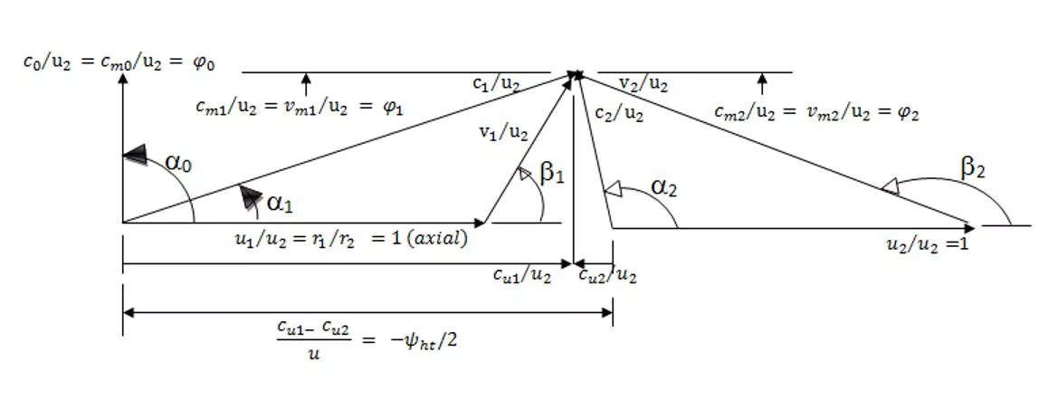
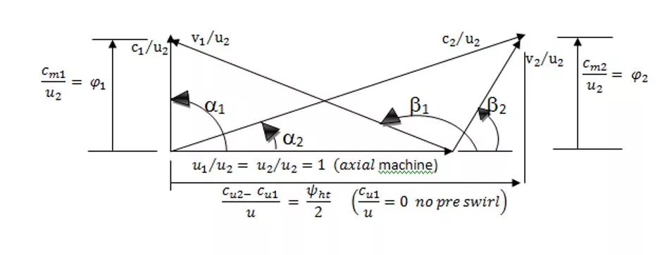
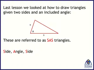
The dimensionless velocity triangles for a passive machine and an active machine are shown
in the two figures beside. All the velocities and velocity components are divided by the
peripheral velocity at the exit (
u
2
)
.
Dimensionless velocity of a passive machine
Dimensionless velocity of an active machine
As mentioned before the
power
coefficient is
defined as


= power coefficient or total enthalpy coefficien
t
=

=
Referring to the Gibbs equatio
n
we can define another similar coefficient for isentropic case:
When neglecting the variation in the kinetic energy, the following definitions can be deduced:
Static enthalpy coefficient
total pressure coefficient
In addition, the discharge coeffici
ent
is defined as the ratio between the meridian velocity
component; either absolute or relative, and the peripheral velocity at rotor exit
:
The degree of reaction
The degree of reaction is a measure of the enthalpy
R
h
(or pressure
R
y
) drop (active machine) or
rise (passive machine) in the stage.
Where
R
h
= degree of reaction based on the enthalpy change
= the static enthalpy change in the rotor
= the static enthalpy change in the stator
= the static enthalpy change in the whole stage
Where
R
y
= degree of reaction based on the pressure change
Sometimes the changes in the rotor and stator and the whole stage is defined by:
Euler’s turbine formula in kinematic form
Euler turbine equation can be in terms of the different velocities affecting the performance of a
turbomachine.
The figure shows a velocity triangle with acute angles. We have to remember that all
components in the direction of the peripheral velocity of rotation are positive and those
against this direction are negative
but
a
n
d
then
Substituting this in the Euler's turbine formula, we get it in its kinematic form.
-
This equation is very important, special for designing the radial machines.
For turbines it is normal to make the stage to be centripetal (u1
u
2
) in order to increase the
work extracted from the fluid. In some rare cases, especially in steam turbines, the expansion
increases the specific volume and hence decreases the density which in turn increases the
velocity because in centripetal machine the exit area is at smaller radius and accordingly small
area. To decrease this undesired effect the machine is built centrifugal one and the not
required effect of positive increase of the peripheral kinetic energy is beared on the other two
ones (absolute and relative). This in turn increases the acceleration of the rotor and stator. As
there is no danger referred to the boundary layers as long the material can bear and that we
are far from sonic velocity region.
This cannot be found in passive radial machine. The normal case is to increase the
peripheral kinetic energy to increase the energy of the fluid, which means centrifugal
machine. If the direction in the stage is inversed the machine will be centripetal one, and
then the deceleration in the cascades of the rotor and stator increases and the tendency
of flow separation increases. Therefore it is forbidden to make a passive radial machine
centripetal one.
In the following slides, come cases of axial, diagonal machines are give
n.
The effect of the change in
the diameter of the blowers
and pumps (increase;
centrifugal) works in
increasing the pressure
ratio. According to the
design of the impeller,
diffuser (stator), and the
revolution number; (this
determines the value of the
specific speed), the range of
the pressure ratio is
determined as shown in the
figure.
The figure indicates a
centripetal turbine (inward
flow)
0-1
bladed stator (nozzles)
1-2 inward radial impeller
•
from lower location through the
rotor through the stator and rotation
to the right direction, the machine
works as axial pump stage
•
from upper location through the
stator through the rotor and rotation
to the left direction, the machine
works as axial turbine stage
This type of machines are used for
storage of energy.
An axial stage works according to
the flow and rotation direct
ion
The figure shows a cross-
section in a turbo charger. It
consists of an axial turbine
stage works with the flue
gases (right) and derive 3-
stages radial compressor (left).
The figure shows a multistage
radial (six stages) compressor.
It can be observed from
narrowing the channels from
stage to stage that is handling
with compressible working
fluid
The figure shows a
high pressure feed
pump with 6
centrifugal stages.
It can be seen that
the different stages
have the same size
as the working fluid
is water
(incompressible)
A figure shows a civil turbo jet. The
machine consists of 6-stages (two axis)
axial turbine working by the hot gases
coming from the combustion chamber.
The compressor works on the same
pressure ratio of the turbine but it
consists of about 16 stage an a rotating
fan makes a bypass separate the
incoming air into two parts the upper
one thrust direct the compressed air
and the rest flows through the 16- stage
and after increasing its enthalpy in the
combustion chamber it expand in the
turbine only to derive the compressor
and the exiting flow with high energy
will expand in a nozzle to give the rest of
thrust to the machine.
In spite the compressor and the turbine
work on the same pressure difference,
the number of compressor stages is
greater than that for the turbine
because of the danger of flow
separation in the compressor and the
compression must occur very gradual
and slowly.
Explore the concept of dimensionless velocity triangles for passive and active machines, power coefficients, Gibbs equation, static enthalpy coefficients, degree of reaction based on enthalpy and pressure changes, and Euler's turbine formula in kinematic form. Gain insights into the relationships and calculations vital for analyzing turbomachinery performance.

Download Presentation

Please find below an Image/Link to download the presentation.
The content on the website is provided AS IS for your information and personal use only. It may not be sold, licensed, or shared on other websites without obtaining consent from the author. Download presentation by click this link. If you encounter any issues during the download, it is possible that the publisher has removed the file from their server.
E N D
Presentation Transcript
6thlecture Dimensionless velocity triangles and relations
= The dimensionless velocity triangles for a passive machine and an active machine are shown in the two figures beside. All the velocities and velocity components are divided by the peripheral velocity at the exit (u2). As mentioned before the power coefficient is defined as = power coefficient or total enthalpy coefficient Dimensionless velocity of a passive machine = Dimensionless velocity of an active machine
Referring to the Gibbs equation we can define another similar coefficient for isentropic case: total pressure coefficient When neglecting the variation in the kinetic energy, the following definitions can be deduced: Static enthalpy coefficient In addition, the discharge coefficient component; either absolute or relative, and the peripheral velocity at rotor exit: is defined as the ratio between the meridian velocity
The degree of reaction The degree of reaction is a measure of the enthalpy Rh(or pressure Ry) drop (active machine) or rise (passive machine) in the stage. Where Rh= degree of reaction based on the enthalpy change = the static enthalpy change in the rotor = the static enthalpy change in the stator = the static enthalpy change in the whole stage Where Ry= degree of reaction based on the pressure change Sometimes the changes in the rotor and stator and the whole stage is defined by:
- Euler s turbine formula in kinematic form Euler turbine equation can be in terms of the different velocities affecting the performance of a turbomachine. The figure shows a velocity triangle with acute angles. We have to remember that all components in the direction of the peripheral velocity of rotation are positive and those against this direction are negative C cm=vm V vu u but Cu and then Substituting this in the Euler's turbine formula, we get it in its kinematic form.
This equation is very important, special for designing the radial machines. For turbines it is normal to make the stage to be centripetal (u1 u2) in order to increase the work extracted from the fluid. In some rare cases, especially in steam turbines, the expansion increases the specific volume and hence decreases the density which in turn increases the velocity because in centripetal machine the exit area is at smaller radius and accordingly small area. To decrease this undesired effect the machine is built centrifugal one and the not required effect of positive increase of the peripheral kinetic energy is beared on the other two ones (absolute and relative). This in turn increases the acceleration of the rotor and stator. As there is no danger referred to the boundary layers as long the material can bear and that we are far from sonic velocity region. This cannot be found in passive radial machine. The normal case is to increase the peripheral kinetic energy to increase the energy of the fluid, which means centrifugal machine. If the direction in the stage is inversed the machine will be centripetal one, and then the deceleration in the cascades of the rotor and stator increases and the tendency of flow separation increases. Therefore it is forbidden to make a passive radial machine centripetal one. In the following slides, come cases of axial, diagonal machines are given.
The effect of the change in the diameter of the blowers and pumps (increase; centrifugal) works in increasing the pressure ratio. According to the design of the impeller, diffuser (stator), and the revolution number; (this determines the value of the specific speed), the range of the pressure ratio is determined as shown in the figure.
The figure indicates a centripetal turbine (inward flow) 0-1 bladed stator (nozzles) 1-2 inward radial impeller
An axial stage works according to the flow and rotation direction from lower location through the rotor through the stator and rotation to the right direction, the machine works as axial pump stage from upper location through the stator through the rotor and rotation to the left direction, the machine works as axial turbine stage This type of machines are used for storage of energy.
The figure shows a cross- section in a turbo charger. It consists of an axial turbine stage works with the flue gases (right) and derive 3- stages radial compressor (left).
The figure shows a multistage radial (six stages) compressor. It can be observed from narrowing the channels from stage to stage that is handling with compressible working fluid
The figure shows a high pressure feed pump with 6 centrifugal stages. It can be seen that the different stages have the same size as the working fluid is water (incompressible)
A figure shows a civil turbo jet. The machine consists of 6-stages (two axis) axial turbine working by the hot gases coming from the combustion chamber. The compressor works on the same pressure ratio of the turbine but it consists of about 16 stage an a rotating fan makes a bypass separate the incoming air into two parts the upper one thrust direct the compressed air and the rest flows through the 16- stage and after increasing its enthalpy in the combustion chamber it expand in the turbine only to derive the compressor and the exiting flow with high energy will expand in a nozzle to give the rest of thrust to the machine. In spite the compressor and the turbine work on the same pressure difference, the number of compressor stages is greater than that for the turbine because of the danger of flow separation in the compressor and the compression must occur very gradual and slowly.