Digital Electronic Circuit Design: BBM 231 Lecture Information
This content provides detailed information about the BBM 231 course covering topics such as lecture schedules, lab sections, grading criteria, lab assistants, contact information, motivation behind studying digital circuits, characteristics of digital systems, representation in electronics circuits, and more. It outlines essential concepts like logic gates, Boolean algebra, Verilog projects, and the significance of understanding digital systems in today's technological world.

Uploaded on Sep 23, 2024 | 3 Views
Download Presentation

Please find below an Image/Link to download the presentation.
The content on the website is provided AS IS for your information and personal use only. It may not be sold, licensed, or shared on other websites without obtaining consent from the author.If you encounter any issues during the download, it is possible that the publisher has removed the file from their server.
You are allowed to download the files provided on this website for personal or commercial use, subject to the condition that they are used lawfully. All files are the property of their respective owners.
The content on the website is provided AS IS for your information and personal use only. It may not be sold, licensed, or shared on other websites without obtaining consent from the author.
E N D
Presentation Transcript
BBM 231 Mant ksal Tasar m M. nder Efe onderefe@cs.hacettepe.edu.tr 1
Lecture Three hours a week (three credits) No other sections, please register this section Monday: 15:00 17:45 (M012) Attendance is advised 2
BBM 233 Lab Three sections Check from the dept. website 7 experiments Once in two weeks It is obligatory to do all the assignments See assistants for grading scheme Work in groups of two 3
Grading One midterm exam Weight: 30% November 11, 2013 Final exam Weight: 40% As scheduled by the registration office Verilog project 30% You need to learn Verilog HDL 4
Lab Assistants O uzhan G l Ali a layan H seyin Temu in (Verilog) 5
Contact Information M. nder Efe Place: CS, 1st Floor, Room 115 e-mail: onderefe @ cs.hacettepe edu.tr Office hours: Whenever you find me Or by appointment 6
Motivation Analysis & design of digital electronic circuits Why digital circuits? They are everywhere and generic digital computers, smart phones, data communication, digital recording, digital TV, many others Fundamental concepts in the design of digital systems Basic tools for the design of digital circuits Logic gates (AND, OR, NOT) Boolean algebra 7
What is a Digital System? One characteristic: Ability of manipulating discrete elements of information A set that has a finite number of elements contains discrete information Examples for discrete sets Decimal digits {0, 1, , 9} Alphabet {A, B, , Y, Z} Binary digits {0, 1} One important problem how to represent the elements of discrete sets in physical systems? 8
How to Represent? In electronics circuits, we have electrical signals voltage current Different strengths of a physical signal can be used to represent elements of the discrete set. Which discrete set? Binary set is the easiest two elements {0, 1} Just two signal levels: 0 V and 5 V This is why we use binary system to represent the information in digital systems. 9
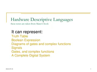
How to Represent? In electronics circuits, we have electrical signals voltage current Base current 4.5 A Collector current 4.5mA +5V 1k F=1000 1M +5V or 0V 0V 10
Binary System Binary set {0, 1} The elements of binary set, 0 and 1 are called binary digits or shortly bits . How to represent the elements of other discrete sets Decimal digits {0, 1, , 9} Alphabet {A, B, , Y, Z} Elements of any discrete set can be represented using groups of bits. 9 1001 A 1010 11
How Many Bits? What is the formulae for number of bits to represent a discrete set of n elements {0, 1, 2, 3} 00 0, 01 1, 10 2, and 11 3. {0, 1, 2, 3, 4, 5, 6, 7} 000 0, 001 1, 010 2, ands 011 3 100 4, 101 5, 110 6, ands 111 7. The formulae, then, #of bits required= log2 #of Symbols If n = 9, then ? bits are needed 12
Nature of Information Is information of discrete nature? Sometimes, but usually not. Anything related to money (e.g. financial computations, accounting etc) involves discrete information In nature, information comes in a continuous form temperature, humidity level, air pressure, etc. Continuous data must be converted (i.e. quantized) into discrete data lost of some of the information We need ADC (DAC) 13
General-Purpose Computers Best known example for digital systems Components CPU, I/O units, Memory unit Outside world CPU Memory Inter connect I/O Registers ALU Control FPU Multiplier/ Divider CPU General-purpose computer 14
Textbook & References Textbook M. Morris ManoDigital Design: With an Introduction to the Verilog HDL, 5th Edition, Prentice Hall, 2013. Other references Tens of digital design books Lectures from MIT Open Courseware and Stanford 15
Contents 1 Digital Systems and Binary Numbers 1 1.1 Digital Systems 1 1.2 Binary Numbers 3 1.3 Number Base Conversions 6 1.4 Octal and Hexadecimal Numbers 8 1.5 Complements of Numbers 10 1.6 Signed Binary Numbers 14 1.7 Binary Codes 18 1.8 Binary Storage and Registers 27 1.9 Binary Logic 30 16
Contents 2 Boolean Algebra and Logic Gates 38 2.1 Introduction 38 2.2 Basic Definitions 38 2.3 Axiomatic Definition of Boolean Algebra 40 2.4 Basic Theorems and Properties of Boolean Algebra 43 2.5 Boolean Functions 46 2.6 Canonical and Standard Forms 51 2.7 Other Logic Operations 58 2.8 Digital Logic Gates 60 2.9 Integrated Circuits 66 17
Contents 3 Gate Level Minimization 73 3.1 Introduction 73 3.2 The Map Method 73 3.3 Four Variable K-Map 80 3.4 Product of Sums Simplification 84 3.5 Don t Care Conditions 88 3.6 NAND and NOR Implementation 90 3.7 Other Two Level Implementations 97 3.8 Exclusive OR Function 103 3.9 Hardware Description Language 108 18
Contents 4 Combinational Logic 125 4.1 Introduction 125 4.2 Combinational Circuits 125 4.3 Analysis Procedure 126 4.4 Design Procedure 129 4.5 Binary Adder Subtractor 133 4.6 Decimal Adder 144 4.7 Binary Multiplier 146 4.8 Magnitude Comparator 148 4.9 Decoders 150 4.10 Encoders 155 4.11 Multiplexers 158 4.12 HDL Models of Combinational Circuits 164 19
Contents 5 Synchronous Sequential Logic 190 5.1 Introduction 190 5.2 Sequential Circuits 190 5.3 Storage Elements: Latches 193 5.4 Storage Elements: Flip Flops 196 5.5 Analysis of Clocked Sequential Circuits 204 5.6 Synthesizable HDL Models of Sequential Circuits 217 5.7 State Reduction and Assignment 231 5.8 Design Procedure 236 20
Contents 6 Registers and Counters 255 6.1 Registers 255 6.2 Shift Registers 258 6.3 Ripple Counters 266 6.4 Synchronous Counters 271 6.5 Other Counters 278 6.6 HDL for Registers and Counters 283 21
Contents 7 Memory and Programmable Logic 299 7.1 Introduction 299 7.2 Random Access Memory 300 7.3 Memory Decoding 307 7.4 Error Detection and Correction 312 7.5 Read Only Memory 315 7.6 Programmable Logic Array 321 7.7 Programmable Array Logic 325 7.8 Sequential Programmable Devices 329 22
Contents (If time permits) 8 Design at the Register Tr a n s f e r L e v e l 351 8.1 Introduction 351 8.2 Register Transfer Level Notation 351 8.3 Register Transfer Level in HDL 354 8.4 Algorithmic State Machines (ASMs) 363 8.5 Design Example (ASMD Chart) 371 8.6 HDL Description of Design Example 381 8.7 Sequential Binary Multiplier 391 8.8 Control Logic 396 8.9 HDL Description of Binary Multiplier 402 8.10 Design with Multiplexers 411 8.11 Race Free Design (Software Race Conditions) 422 8.12 Latch Free Design (Why Waste Silicon?) 425 8.13 Other Language Features 426 23


")