Hardware Descriptive Languages in Digital Systems

undefined
 
2024-09-18
 
1
 
Hardware Descriptive Languages
these notes are taken from Mano’s book
 
It can represent:
Truth Table
Boolean Expression
Diagrams of gates and complex functions
Signals
Gates, and complex functions
A Complete Digital System
 
 
2024-09-18
 
2
 
HDL, Area of Application
 
Design Entry
Logic Simulation
Functional Verification
Digital Circuit Synthesis
Timing Verification
Fault Simulation
Documntation
 
 
2024-09-18
 
3
 
Declarations
 
Language Manual describes Syntax
Reserved words….around 100
Reserved words are lower case:
module, endmodule, input, output, wire, timescale…..
// is used for comments
/*….*/ Is used for multi-line comments
Blank spaces are ignored
Blank spaces may not appear within a reserved word,
identifier, an operator or a number
 
2024-09-18
 
4
 
Declarations
 
Verilog is case sensitive
m
o
d
u
l
e
 
.
.
 
M
u
s
t
 
b
e
 
c
l
o
s
e
d
 
w
i
t
h
 
e
n
d
m
o
d
u
l
e
 
a
n
d
t
h
e
r
e
 
i
s
 
n
o
 
;
 
a
f
t
e
r
 
e
n
d
m
o
d
u
l
e
.
Combinational Logic
 
can be described by:
 Boolean Equations ,
Truth Table,
Schematic Capture
A digital System can be modeled in structural,
algorithmic or behavioural.
 
2024-09-18
 
5
 
Identifiers
 
Are case sensitive,
M
u
s
t
 
N
O
T
 
s
t
a
r
t
 
w
i
t
h
 
n
u
m
e
r
i
c
 
c
h
a
r
a
c
t
e
r
s
They may contain the underscore “ _”
Example:
Asim
Al_Khalili
Al-khalili
COEN212
 
2024-09-18
 
6
 
Verilog Constructs
 
E
a
c
h
 
m
o
d
u
l
e
 
s
t
a
r
t
s
 
w
i
t
h
 
r
e
s
e
r
v
e
d
 
w
o
r
d
 
m
o
d
u
l
e
 
a
n
d
e
n
d
s
 
w
i
t
h
 
e
n
d
m
o
d
u
l
e
.
T
h
e
 
p
o
r
t
 
l
i
s
t
 
i
s
 
e
n
c
l
o
s
e
d
 
w
i
t
h
i
n
 
p
a
r
e
n
t
h
e
s
i
s
.
 
C
o
m
m
a
s
a
r
e
 
u
s
e
d
 
t
o
 
s
e
p
a
r
a
t
e
 
t
h
e
 
e
l
e
m
e
n
t
s
.
A
l
l
 
s
t
a
t
e
m
e
n
t
s
 
m
u
s
t
 
e
n
d
 
w
i
t
h
 
a
 
;
.
i
n
p
u
t
 
a
n
d
 
o
u
t
 
d
e
f
i
n
e
 
t
h
e
 
p
o
r
t
s
.
w
i
r
e
 
d
e
f
i
n
e
s
 
t
h
e
 
i
n
t
e
r
n
a
l
 
c
o
n
n
e
c
t
i
o
n
s
.
G
a
t
e
s
 
a
r
e
 
d
e
f
i
n
e
d
 
w
i
t
h
 
r
e
s
e
r
v
e
d
 
w
o
r
d
s
 
a
n
d
,
 
n
o
t
 
o
r
 
E
a
c
h
 
g
a
t
e
 
i
s
 
c
a
l
l
e
d
 
b
y
 
a
 
g
a
t
e
 
i
n
s
t
a
n
t
i
a
t
i
o
n
.
 
G
a
t
e
s
n
a
m
e
s
 
a
r
e
 
o
p
t
i
o
n
a
l
 
b
u
t
 
h
e
l
p
 
i
n
 
i
d
e
n
t
i
f
y
i
n
g
 
t
h
e
 
c
i
r
c
u
i
t
.
G
a
t
e
 
o
u
t
p
u
t
,
 
i
n
p
u
t
s
 
a
r
e
 
o
r
d
e
r
e
d
 
s
e
p
a
r
a
t
e
d
 
w
i
t
h
 
a
c
o
m
m
a
 
a
n
d
 
e
n
c
l
o
s
e
d
 
b
y
 
p
a
r
e
n
t
h
e
s
i
s
.
 
 
2024-09-18
 
7
 
Example 
(Mano’s book 4thEdition
)


/
/
 
V
e
r
i
l
o
g
 
m
o
d
e
l
 
c
i
r
c
u
i
t
 
o
f
 
a
b
o
v
e
 
f
i
g
u
r
e
.
 
I
E
E
E
 
1
3
6
4
-
1
9
9
5
 
S
y
n
t
a
x
m
o
d
u
l
e


S
i
m
p
l
e
_
C
i
r
c
u
i
t
 
(
A
,
B
,
C
,
D
,
E
)
;
o
u
t
p
u
t


D
,
E
;
i
n
p
u
t


A
,
B
,
C
;
w
i
r
e


w
1
;
 
a
n
d


G
1
 
(
w
1
,
A
,
B
)
;
n
o
t


G
2
 
(
E
,
C
)
;
o
r


G
3
 
(
D
,
w
1
,
E
)
;
e
n
d
m
o
d
u
l
e
 
2024-09-18
 
8
 
Delays
 
The propagation delay is specified  in terms of time
units and is specified by the symbol #
and 
   #(10) G1  (w1, A,B)
The association of time unit and the time scale is
made with the compiler directive
              ‘timescale
The directive is specified before the declaration of a
module
‘timescale
 1 ns/100ps indicates unit of measurement
for time delay  followed by the precision round off.
 
2024-09-18
 
9
 
Test Bench
 
/
/
 
T
e
s
t
 
b
e
n
c
h
 
f
o
r
 
S
i
m
p
l
e
_
C
i
r
c
u
i
t
_
_
d
e
l
a
y
m
o
d
u
l
e
 
t
_
S
i
m
p
l
e
_
C
i
r
c
u
i
t
_
d
e
l
a
y
;
w
i
r
e


D
,
E
;


/
/
 
c
i
r
c
u
i
t
 
o
u
t
p
u
t
 
o
f
 
t
h
e
 
c
i
r
c
u
i
t
 
t
o
 
b
e
 
t
s
t
e
d
 
w
i
t
h
i
n
 
t
h
e
 
t
e
s
t
 
b
e
n
c
h
r
e
g


A
,
B
,
C
;


/
/
 
o
u
t
p
u
t
 
f
r
o
m
 
s
t
i
m
u
l
a
t
o
r
 
 
a
n
d
 
i
n
p
u
t
 
t
o
 
t
h
e
 
c
i
r
c
u
i
t
S
i
m
p
l
e
_
C
i
r
c
u
i
t
_
d
e
l
a
y
 
M
1
 
(
A
,
B
,
C
,
D
,
E
)
;
 
 
/
/
i
n
s
t
a
n
t
i
a
t
i
o
n
 
o
f
 
M
1
I
n
i
t
i
a
l


/
/
 
s
t
a
t
e
m
e
n
t
 
t
o
 
d
e
s
c
r
i
b
e
 
t
h
e
 
t
e
s
t
i
n
g
 
w
a
v
e
f
o
r
m


b
e
g
i
n


A
=
 
1
b
0
;
 
B
=
1
b
0
;
 
C
=
1
b
0
;
 
 
/
/
 
o
n
e
 
b
i
n
a
r
y
 
d
i
g
i
t
 
w
i
t
h
 
a
 
v
a
l
u
e
 
o
f
 
0
 
f
o
r
 
A
,
B
 
a
n
d
 
C


#
1
0
0
 
A
=
1
b
1
;
 
B
=
1
b
1
;
 
C
=
1
b
1
;


/
/
 
a
f
t
e
r
 
1
0
0
 
n
s
 
i
n
p
u
t
s
 
a
r
e
 
c
h
a
n
g
e
d
 
t
o
 
A
B
C
 
1
1
1


e
n
d
I
n
i
t
i
a
l
 
#
2
0
0
 
$
f
i
n
i
s
h
;
 
 
/
/
 
e
n
d
 
o
f
 
t
h
e
 
t
e
s
t
 
a
p
p
l
i
c
a
t
i
o
n
,
 
i
e
.
 
e
n
t
i
r
e
 
t
e
s
t
 
s
i
m
u
l
a
t
i
o
n
 
t
i
m
e
e
n
d
m
o
d
u
l
e
 
2024-09-18
 
10
 
Example
(Mano’s book 4thEdition
)


/
/
 
V
e
r
i
l
o
g
 
m
o
d
e
l
 
c
i
r
c
u
i
t
 
o
f
 
a
b
o
v
e
 
f
i
g
u
r
e
.
 
I
E
E
E
 
1
3
6
4
-
1
9
9
5
 
S
y
n
t
a
x
 
m
o
d
u
l
e


S
i
m
p
l
e
_
C
i
r
c
u
i
t
_
w
i
t
h
_
d
e
l
a
y
 
(
A
,
B
,
C
,
D
,
E
)
;
o
u
t
p
u
t


D
,
E
;
i
n
p
u
t


A
,
B
,
C
;
w
i
r
e


w
1
;
a
n
d


#
(
3
0
)
 
G
1
 
(
w
1
,
A
,
B
)
;
n
o
t


#
(
1
0
)
 
G
2
 
(
E
,
C
)
;
o
r


#
(
2
0
)
G
3
 
(
D
,
w
1
,
E
)
;
e
n
d
m
o
d
u
l
e
 
 
2024-09-18
 
11
 
Example 
(Mano’s book 4thEdition
)


A
B
C
W1
E
D


1
0
0
 
 
1
1
0


1
3
0


1
5
0
 
2024-09-18
 
12
 
Boolean Expressions
 
Use reserved word 
assign
 and
 
&
, 
| 
and 
~
 for AND,OR,NOT
Example:
/
/
 
B
o
o
l
e
a
n
 
C
i
r
c
u
i
t
 
r
e
p
r
e
s
e
n
t
a
t
i
o
n
m
o
d
u
l
e
 
B
o
o
l
e
a
n
 
C
i
r
c
u
i
t
 
(
E
,
F
,
A
,
B
,
C
,
D
)
;
o
u
t
p
u
t
 
 
E
,
F
;
i
n
p
u
t


A
,
B
,
C
,
D
;
a
s
s
i
g
n
 
 
E
=
 
A
|
 
(
B
&
C
)
|
(
~
B
&
D
)
;


/
/
 
A
 
+
 
 
(
B
.
C
)
 
+
 
(
B
.
D
)
a
s
s
i
g
n
 
F
=
 
(
~
B
 
&
C
)
 
|
 
(
B
&
 
~
C
 
&
 
~
D
)
;


/
/
 
(
B
.
C
)
 
+
 
(
B
.
C
.
D
)
e
n
d
m
o
d
u
l
e
 
2024-09-18
 
13
 
User Defined Primitives
 
S
y
s
t
e
m
 
p
r
i
m
i
t
i
v
e
s
:
 
 
a
n
d
,
 
o
r
,
 
n
a
n
d
,
 
x
o
r
One way is to define own primitive by  a Truth Table….
U
s
e
 
p
r
i
m
i
t
i
v
e
 
a
n
d
 
e
n
d
p
r
i
m
i
t
i
v
e
 
t
o
 
c
r
e
a
t
e
 
a
 
U
D
P
I
t
 
i
s
 
d
e
c
l
a
r
e
d
 
w
i
t
h
 
t
h
e
 
r
e
s
e
r
v
e
d
 
w
o
r
d
 
p
r
i
m
i
t
i
v
e
 
f
o
l
l
o
w
e
d
 
b
y
 
a
n
a
m
e
 
a
n
d
 
p
o
r
t
 
l
i
s
t
One output and it must be listed first in the port listing and
following the 
output
 declaration
Any number of inputs, however the order given in the port
declaration must be the same as the Table
T
h
e
 
t
a
b
l
e
 
m
u
s
t
 
 
s
t
a
r
t
 
w
i
t
h
 
t
h
e
 
r
e
s
e
r
v
e
d
 
w
o
r
d
 
t
a
b
l
e
 
a
n
d
 
e
n
d
 
w
i
t
h
e
n
d
t
a
b
l
e
The values of the inputs are listed in order and separated from
output by : the line ends with ;
 
 
2024-09-18
 
14
 
User Defined Primitives
 
Example:
/
/
 
V
e
r
i
l
o
g
 
m
o
d
e
l
:
 
U
s
e
r
 
D
e
f
i
n
e
d
 
P
r
i
m
i
t
i
v
e
p
r
i
m
i
t
i
v
e
 
U
D
P
_
0
2
4
6
7
 
(
D
,
A
,
B
,
C
)
;
o
u
t
p
u
t
 
D
;
i
n
p
u
t
 
A
,
B
,
C
;
/
/
 
T
r
u
t
h
 
T
a
b
l
e
 
f
o
r
 
D
=
 
f
(
 
A
,
 
B
 
,
C
 
)
 
=
 
Σ
 
m
(
0
,
2
,
4
,
6
,
7
)
;
t
a
b
l
e


/
/


A


B


C


:


D


/
/
 
h
e
a
d
e
r
s


e
n
d
t
a
b
l
e
e
n
d
p
r
i
m
i
t
i
v
e
 
2024-09-18
 
15
 
Calling of UDP
 
/
/
 
V
e
r
i
l
o
g
 
m
o
d
e
l
:
 
C
i
r
c
u
i
t
 
i
n
s
t
a
n
t
i
a
t
i
o
n
 
o
f
 
C
i
r
c
u
i
t
_
U
P
D
_
0
2
4
6
7
m
o
d
u
l
e
 
C
i
r
c
u
i
t
_
w
i
t
h
 
U
D
P
_
0
2
4
6
7
 
(
e
,
f
,
a
,
b
,
c
,
d
)
;
o
u
t
p
u
t
 
e
,
f
;
i
n
p
u
t
 
a
,
b
,
c
,
d
;
U
D
P
_
0
2
4
6
7
 
 
(
e
,
a
,
b
,
c
)
;
a
n
d


(
f
,
e
,
d
)
;
e
n
d
m
o
d
u
l
e
 
UDP_02467
 
a
b
c
 
d
 
e
 
f
 
16
 
-- Interface                               …………  
1
1
entity
entity
 
 
  XOR_2  
  XOR_2  
is 
is 
                          
                          
………………  2
………………  2
Port 
Port 
                                                 
                                                 
……………… .3
……………… .3
(A,B :  
(A,B :  
in 
in 
 BIT;   Z :  
 BIT;   Z :  
out
out
  
  
BIT);        …………… 4
end
end
 
 
XOR_2;                                    ………………   5
-- Body                                 …………   …
6
6
architecture
architecture
  DATA_FLOW  
  DATA_FLOW  
of
of
  
  
X
X
OR_2  
OR_2  
is 
is 
 
 
 …7
 …7
signal
signal
 
 
  Sig 1, Sig 2: BIT;                            ……… 8
  Sig 1, Sig 2: BIT;                            ……… 8
begin 
begin 
                                                 
                                                 
………………9
………………9
Sig 1 <= A  
Sig 1 <= A  
and  not
and  not
 B;                    …………… ..10
 B;                    …………… ..10
Sig 2 <= B 
Sig 2 <= B 
and  not
and  not
 A;                     ………………11
 A;                     ………………11
   Z    <=Sig1 
   Z    <=Sig1 
or
or
  Sig 2;                           ……………12
  Sig 2;                           ……………12
end
end
  
  
DATA_FLOW;                             ……………13
 
 
Signal
Declaration
 
Reserved
word
 
Concurrent
assignment
statement
 
V
H
D
L
 
E
X
A
M
P
L
E
 
17
 
AND Gate simulation (VHDL)
 
18
 
l
i
b
r
a
r
y
 
i
e
e
e
;
u
s
e
 
i
e
e
e
.
s
t
d
_
l
o
g
i
c
_
1
1
6
4
.
a
l
l
;
e
n
t
i
t
y
 
F
u
l
l
_
A
d
d
e
r
 
i
s
-
-
 
g
e
n
e
r
i
c
 
(
T
S
 
:
 
T
I
M
E
 
:
=
 
0
.
1
1
 
n
s
;
 
T
C
 
:
 
T
I
M
E
 
:
=
 
0
.
1
 
n
s
)
;


p
o
r
t
 
(
X
,
 
Y
,
 
C
i
n
:
 
i
n
 
s
t
d
_
l
o
g
i
c
;
 
C
o
u
t
,
 
S
u
m
:
 
o
u
t
 
 
s
t
d
_
l
o
g
i
c
)
;
e
n
d
 
F
u
l
l
_
A
d
d
e
r
;
a
r
c
h
i
t
e
c
t
u
r
e
 
C
o
n
c
u
r
r
e
n
t
 
o
f
 
F
u
l
l
_
A
d
d
e
r
 
i
s
b
e
g
i
n


S
u
m
 
<
=
 
 
X
 
x
o
r
 
Y
 
x
o
r
 
C
i
n
 
a
f
t
e
r
 
0
.
1
1
 
n
s
 
;


C
o
u
t
 
<
=
 
(
X
 
a
n
d
 
Y
)
 
o
r
 
(
X
 
a
n
d
 
C
i
n
)
 
o
r
 
(
Y
 
a
n
d
 
C
i
n
)
 
a
f
t
e
r
 
0
.
1
1
 
n
s
;
e
n
d
 
C
o
n
c
u
r
r
e
n
t
;
 
 
VHDL      Full Adder Example
 
 
E
x
a
m
p
l
e
 
:
 
 
V
H
D
L
 
M
u
l
t
i
p
l
i
e
r
,
 
S
i
m
u
l
a
t
i
o
n
 
R
e
s
u
l
t
s
M
u
l
t
i
p
l
i
c
a
n
d
 
=
 
1
0
0
0
1
0
0
1
2
=
8
9
1
6
M
u
l
t
i
p
l
i
e
r
 
=
1
0
1
0
1
0
1
1
2
=
A
B
1
6
E
x
p
e
c
t
e
d
 
R
e
s
u
l
t
 
=
1
0
1
1
0
1
1
1
0
0
0
0
0
1
1
2
=
5
B
8
3
1
6
Slide Note
Embed
Share

Hardware Descriptive Languages (HDLs) are used to represent various aspects of digital systems, including truth tables, Boolean expressions, gate diagrams, and complex functions. They find application in design entry, logic simulation, functional verification, circuit synthesis, timing verification, fault simulation, and documentation. The language manual for declarations in HDL describes syntax, reserved words, and rules for identifiers. Verilog, a case-sensitive language, allows modeling of digital systems using structural, algorithmic, or behavioral approaches. Verilog constructs involve modules, port lists, gates, and gate instantiations. An example circuit model is presented to demonstrate Verilog syntax, including gate connections and output definitions.

  • Hardware Descriptive Languages
  • Digital Systems
  • Verilog
  • Circuit Modeling
  • Syntax Rules

Uploaded on Sep 18, 2024 | 0 Views


Download Presentation

Please find below an Image/Link to download the presentation.

The content on the website is provided AS IS for your information and personal use only. It may not be sold, licensed, or shared on other websites without obtaining consent from the author. Download presentation by click this link. If you encounter any issues during the download, it is possible that the publisher has removed the file from their server.

E N D

Presentation Transcript


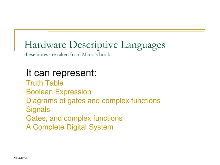
  1. Hardware Descriptive Languages these notes are taken from Mano s book It can represent: Truth Table Boolean Expression Diagrams of gates and complex functions Signals Gates, and complex functions A Complete Digital System 2024-09-18 1

  2. HDL, Area of Application Design Entry Logic Simulation Functional Verification Digital Circuit Synthesis Timing Verification Fault Simulation Documntation 2024-09-18 2

  3. Declarations Language Manual describes Syntax Reserved words .around 100 Reserved words are lower case: module, endmodule, input, output, wire, timescale .. // is used for comments /* .*/ Is used for multi-line comments Blank spaces are ignored Blank spaces may not appear within a reserved word, identifier, an operator or a number 2024-09-18 3

  4. Declarations Verilog is case sensitive module .. Must be closed with endmodule and there is no ; after endmodule. Combinational Logic can be described by: Boolean Equations , Truth Table, Schematic Capture A digital System can be modeled in structural, algorithmic or behavioural. 2024-09-18 4

  5. Identifiers Are case sensitive, Must NOT start with numeric characters They may contain the underscore _ Example: Asim Al_Khalili Al-khalili COEN212 2024-09-18 5

  6. Verilog Constructs Each module starts with reserved word module and ends with endmodule. The port list is enclosed within parenthesis. Commas are used to separate the elements. All statements must end with a ; . input and out define the ports. wire defines the internal connections. Gates are defined with reserved words and, not or Each gate is called by a gate instantiation. Gates names are optional but help in identifying the circuit. Gate output, inputs are ordered separated with a comma and enclosed by parenthesis. 2024-09-18 6

  7. Example (Manos book 4thEdition) A B G1 w1 G3 D C G2 E // Verilog model circuit of above figure. IEEE 1364-1995 Syntax module Simple_Circuit (A,B,C,D,E); output D,E; input A,B,C; wire w1; and G1 (w1,A,B); not G2 (E,C); or G3 (D,w1,E); endmodule 2024-09-18 7

  8. Delays The propagation delay is specified in terms of time units and is specified by the symbol # and #(10) G1 (w1, A,B) The association of time unit and the time scale is made with the compiler directive timescale The directive is specified before the declaration of a module timescale 1 ns/100ps indicates unit of measurement for time delay followed by the precision round off. 2024-09-18 8

  9. Test Bench T_Simple_Circuit Test generator Circuit Stimulator Circuit reg wire // Test bench for Simple_Circuit__delay module t_Simple_Circuit_delay; wire D,E; // circuit output of the circuit to be tsted within the test bench reg A,B,C; // output from stimulator and input to the circuit Simple_Circuit_delay M1 (A,B,C,D,E); //instantiation of M1 Initial // statement to describe the testing waveform begin A= 1 b0; B=1 b0; C=1 b0; // one binary digit with a value of 0 for A,B and C #100 A=1 b1; B=1 b1; C=1 b1; // after 100 ns inputs are changed to ABC 111 end Initial #200 $finish; // end of the test application, ie. entire test simulation time endmodule 2024-09-18 9

  10. Example (Mano s book 4thEdition) A (30ns) w1 (20 ns) B G1 G3 D E C G2 (10) ns // Verilog model circuit of above figure. IEEE 1364-1995 Syntax module Simple_Circuit_with_delay (A,B,C,D,E); Input A B C Output E w1 D Time units (ns) output D,E; input A,B,C; 0 0 0 1 0 1 Initial 1 1 1 1 0 1 initial wire w1; 10 1 1 1 0 01 and #(30) G1 (w1,A,B); 20 1 1 1 0 0 1 not #(10) G2 (E,C); 30 1 1 1 0 1 0 40 1 1 1 0 1 0 or #(20)G3 (D,w1,E); 50 1 1 1 0 1 1 endmodule 2024-09-18 10

  11. Example (Manos book 4thEdition) A 30 ns w1 20 ns B G1 G3 D C 10 ns E G2 A B C W1 E D 100 110 130 150 2024-09-18 11

  12. Boolean Expressions Use reserved word assign and &, | and ~ for AND,OR,NOT Example: // Boolean Circuit representation module Boolean Circuit (E,F,A,B,C,D); output E,F; input A,B,C,D; assign E= A| (B&C)|(~B&D); // A + (B.C) + (B .D) assign F= (~B &C) | (B& ~C & ~D); // (B .C) + (B.C .D ) endmodule 2024-09-18 12

  13. User Defined Primitives System primitives: and, or, nand, xor One way is to define own primitive by a Truth Table . Use primitive and endprimitive to create a UDP It is declared with the reserved word primitive followed by a name and port list One output and it must be listed first in the port listing and following the output declaration Any number of inputs, however the order given in the port declaration must be the same as the Table The table must start with the reserved word table and end with endtable The values of the inputs are listed in order and separated from output by : the line ends with ; 2024-09-18 13

  14. User Defined Primitives Example: // Verilog model: User Defined Primitive primitive UDP_02467 (D,A,B,C); output D; input A,B,C; // Truth Table for D= f( A, B ,C ) = m(0,2,4,6,7); table // A B C : D // headers 0 0 0 : 1; 0 0 1 : 0; 0 1 0 : 1; 0 1 1 : 0; 1 0 0 : 1; 1 0 1 : 0; 1 1 0 : 1; 1 1 1 : 1; endtable endprimitive 2024-09-18 14

  15. Calling of UDP // Verilog model: Circuit instantiation of Circuit_UPD_02467 module Circuit_with UDP_02467 (e,f,a,b,c,d); output e,f; input a,b,c,d; UDP_02467 (e,a,b,c); and (f,e,d); endmodule a UDP_02467 e b c f d 2024-09-18 15

  16. VHDL EXAMPLE -- Interface 1 entity XOR_2 is 2 Port .3 (A,B : in BIT; Z : out BIT); 4 end XOR_2; 5 -- Body 6 Signal Reserved word architecture DATA_FLOW of XOR_2 is 7 Declaration signal Sig 1, Sig 2: BIT; 8 begin 9 Sig 1 <= A and not B; ..10 Concurrent assignment statement Sig 2 <= B and not A; 11 Z <=Sig1 or Sig 2; 12 16 end DATA_FLOW; 13

  17. AND Gate simulation (VHDL) 17

  18. VHDL Full Adder Example library ieee; use ieee.std_logic_1164.all; entity Full_Adder is -- generic (TS : TIME := 0.11 ns; TC : TIME := 0.1 ns); port (X, Y, Cin: in std_logic; Cout, Sum: out std_logic); end Full_Adder; architecture Concurrent of Full_Adder is begin Sum <= X xor Y xor Cin after 0.11 ns ; Cout <= (X and Y) or (X and Cin) or (Y and Cin) after 0.11 ns; end Concurrent; 18

  19. Example : VHDL Multiplier, Simulation Results Multiplicand = 100010012 = Multiplier = 101010112 Expected Result = 1011011100000112 =5B8316 8916 AB16 =

More Related Content

giItT1WQy@!-/#giItT1WQy@!-/#giItT1WQy@!-/#giItT1WQy@!-/#giItT1WQy@!-/#giItT1WQy@!-/#giItT1WQy@!-/#giItT1WQy@!-/#giItT1WQy@!-/#