Development of Closed Loop System in Process Control Course II
This content explores the development of a block diagram for a closed-loop system in Process Control Course II, focusing on components like the process, measurement element, controller, control valve, and comparator. It delves into the transfer functions and relationships between these components to achieve desired control in the system.
Download Presentation

Please find below an Image/Link to download the presentation.
The content on the website is provided AS IS for your information and personal use only. It may not be sold, licensed, or shared on other websites without obtaining consent from the author.If you encounter any issues during the download, it is possible that the publisher has removed the file from their server.
You are allowed to download the files provided on this website for personal or commercial use, subject to the condition that they are used lawfully. All files are the property of their respective owners.
The content on the website is provided AS IS for your information and personal use only. It may not be sold, licensed, or shared on other websites without obtaining consent from the author.
E N D
Presentation Transcript
Process Control Course II 2 Lecture Closed Loop system
Development of Block Diagram for closed system Consider the system shown below . We try to construct the block diagram for the CSTH and to find the transfer function ( Regulator and Servo) The main components of the loop are : - Process - Measurement - Controller - Control Valve m cp Ti Temperature measuring element M m cp To Process Now we will discuss each components in details Steam in Q P E Tm Controller Final control element Control Valve Comparator Tsp
1. Process Consider the heating tank which shown in Figure below. The tank represents the process in the closed loop system. Now we will try to find the transfer function for the process which relate the output variable ??? with input variables ??? and the rate of input heat ? ? . Here we will assume that the mass flowrate input to the system (m) is constant. So ??? = ? ??? ,? ? . m Ti cp Now we try to find the transfer function of the process which relate the output variable to the inlet variables. Heat balance M m To cp Process In = out + Accumulation ? .?? .?? + ? = ?.??.?? + ? ????? ?? Q
? ? ???? ??+ ?? = ?? + ? ? ??? ??+ ?? = ?? + 1 ? .?? ? 1 ? =? ? = ? .?? ? ?? + 1 ??? = ??? + ? ? ? 1 ? ??? = ?? + 1 ??+ ?? + 1? ? 1 ??(s) ?? + 1 + ? ??(s) ?(s) ?? + 1 +
2 Measuring Element The temperature-measuring element, which senses the bath temperature ??and transmits a signal ?? to the comparator. ??(s) ??(s) ?? In general the measuring element can be represented by one of the following forms: ??? =??(?) ?? ??(?)= ??? + 1 .. 1 Where ?? is the steady state gain of measuring element ?? is time constant or lag of measuring lag. Sometimes, the time constant of the measuring device ?? is so small that could be neglected, and then the transfer function becomes: ??? =??(?) ??(?)= ?? ..2
3- Comparator The action of the comparator is to compare between the two signals; the output signal from the measuring element ?? and the set point ??? which represent the desired value for the output variable. The output of the comparator represents the error signal ?. + Tsp(s) ?(?) = ??(?) ???(?) E(s) ? - Tm(s)
4. Controller Actually, there are many types of controllers depending on their actions. (Proportional, Integral, Derivative, Proportional- derivative, Proportional-Integral and Proportional-Derivative Integral) The input to the controller is the error signal E(s) E (s) P (s) ?? The output of the controller is hydraulic, pneumatic or electric signal. The controller will manipulate the error signal in such a way to reduce or eliminate the error signal. In general, The output of the controller is hydraulic, pneumatic or electric signal that transfers to the final control element. Here, we shall take the type of the controller as proportional and the output signal is pneumatic p(s), so the transfer function of the controller ??(?) will be: E (s) P (s) ??(?) =?(?) ?? ?(?)= ??
Final control Element (Control valve) Usually, the final control element may be - control valve which operates pneumatically or - solenoid valve which operates electrically. Solenoid Valve Control Valve The input variable to the valve is pressure signal The output will affect the manipulating variable ( in our example is Q) ? (s) P (s) Gv (s) Mostly, the transfer function of the final control element can be represented by either - first - order lag??? =? ? ?? ? ?= ???+1 or - constant. ??? =? ? ? ?= ??
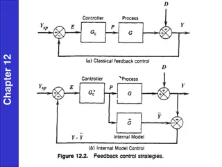
The Block diagram of the closed loop system can be given as in Figure below 1 ?i (s) ?? + 1 + ?(s) ?(s) ?(s) + + ?sp (s) ?? ? ?? (s) ?? ??? + 1 _ ?? + 1 ?? ?m (s) ??? + 1
Representation of closed loop system by symbols and signal transmitters The elements of the closed loop system can be represented by symbols and signals transmitters. Figure below shows the signal transmitter and symbols between measuring element and control valve set point X C X T Measuring element Control valve Transmitter Controller Variable X Temperature T Flow F Pressure P Level L Concentration C
set point T C T T Control valve Measuring element Temperature Controller Temperature Transmitter set point F C F T Control valve Measuring element Flow Controller Flow Transmitter
set point L C L T Control valve Measuring element Level Controller Level Transmitter set point C C C T Control valve Measuring element concentration Controller concentration Transmitter
The type of Signal transmitter can be represented by lines as follows: Signal type Electric signal symbol Pneumatic signal Hydraulics signal set point F C F T Control valve Measuring element Flow Controller Flow Transmitter
m cp Ti m cp Ti Temperature measuring element M M m cp To Process m cp To Process Steam in Steam in Q T T Q P E Tm Controlle r Final control element Control Valve Tc Comparator Tsp Set point
Example 1 Consider the mixing system shown in Fig below Given the following data: Pure A d=2 cm 6 m ??= 7 ???/??? , ? = 14 ?????= 1.5 ,??= 2, ??= 0.75 m (mole/s) Find the followings: ??? ??? ??? ??? ???? and sketch the a. The transfer functions: ?? Set point qi CC signal flow diagram Ci b. The final value of ?? for step change in ?? of value 2 units. c. The final value of ?? for step change in ??? of value 3 units. V CT ?? q d=3 cm co 9 m
Solution a. Process Pure A d=2 cm 6 m + ? = ???? + ???? ???? m (mole/s) ?? ? ????? +1 ??+ ?? = ?? ? ?? ?? qi ? +1 ?? + 1 ?? ? = ?? ? ? ..(1) ?? Ci V But ??? ?? ?= ? ??2? ?? q d=3 cm ?? ? =??? co ? ??2? ..(2) 9 m ? ?? ??? ?? = ? ??1? ? = ??? .? ??1? ..(3) Subs Eq. (3) and (2) in (1)
?? + 1 ??? .???2?= ??? .???1?+1 ? ? ?? (?? + 1)??? .= ??? .? (??1+??2)?+? ??2? ?(?) ?? ??? =? (??1+??2)? ? ??2? ????+1 ? ? ??? + ??+1 ? =? =14 7= 2, Pure A ?? d=2 cm 6 m m (mole/s) ? 4?? ? 40.0226 7 1000 ? 40.032(9) 7/1000 2?1 ?? ??1=?? = = = 0.27 ?? ?? Set point qi ? 4?2 2?2 ?? CC ??2=?? Ci = = = 0.9 ?? V CT ??? =? (0.9+0.27)? ? 0.9? 7(2?+1) ? ? ??? + ?? q d=3 cm 2?+1 co 9 m ??? =? 1.17? ? 0.9? 7(2?+1) ? ? 2?+1 ??? +
??? =?1.17? ? 0.9? 7(2?+1) ? ? ? 1.17? 2? + 1 2?+1 ??? + ?i (s) ??= 1.5 ,??= 2, ??= 0.75 ?(s) ?(s) ?(s) + + ?sp (s) + ? 0.9? 7(2? + 1) ?? (s) 0.75 1.5 _ ?m (s) 2 ? 1.17? 2?+1 ? 1.17? 2?+1 1+0.32? 0.9? 2?+1 a. Transfer function ??? ???= = 1+0.75 1.5 ? 0.9? 2 7(2?+1) ? 1.9? 7(2? + 1 ? 1.9? 2? + 1 (0.75)(1.5) 0.16 ??? ???? ) = = ? 0.9? 7(2? + 1 1 +0.3214? 1.9? 2? + 1 1 + 2(0.75)(1.5) )
b. ? 1.17? 2? + 1 ??? ??? ??? =2 = ? ???? ? ???? 1 +0.32? 0.9? 2? + 1 ? 1.17? 2? + 1 ? 1.17? 2? + 1 2 ?[ ??? = ??? = ] 1 +0.32? 0.9? 2? + 1 1 +0.32? 0.9? 2? + 1 ?? = lim ? 0? ??(?) = 1.515 ? 1.9? 2? + 1 ? 1.9? 2? + 1 0.16 0.16 C. =3 ??? = ???? ? 1 +0.3214? 1.9? 2? + 1 1 +0.3214? 1.9? 2? + 1 ?? = lim ? 0? ??(?) = 0.363
Example 2 For the liquid- level system shown in the Figure below, find ?? a. The transfer function of the process. b. Sketch the signal flow block diagram. ? ? ???? c. The T.F LC d. The response of H if a unit step change occurs in set point and sketch it. ? ?1 V LT ?? Given the following data: ? = 1 ?2 ,?1= 2, ? = 10 ???/???, ? = 5 ???, ??= 1.5, ??= 1, ??= 1
C.V ?? a. Process. Material balance ??= ??+ ??? LC Set point ?? ? ??=?? + ??? ?1 V LT ?? ?1 ?? ?1??? ??+ ? = ?1?? ??? ??+ ? = ?1?? ?? + 1 ? ? = ?1??(?) ?1 ??+1??? , ? = 2, ? = ?.? = 2 2 2? + 1??? ?? ? ? = ? ? ? = ?1 V ?? There is only Process Gp, no load GL exist ??? =? ? 2 = ??? 2? + 1
?(s) E(s) + 2 b. ???(s) 1.5 2? + 1 - c. Note that Gc=1 and Gm=1 , and no need to put them in the block diagram. 1.5 2 2? + 1 1 +1.5 2 2? + 1 ? ? ???? 3 = = 2? + 4 ? ? ???? 3/4 0.75 0.5? + 1 ? ? = = 0.5? + 1= d. ?(?) Response for unit step change in servo ? ? = 1???? .? ? 0.75 ? ? = 11 0.75 0.5? + 1= 0.75(1 ? 2?) ?. 0 ?
The End Thank you for listening Any ?
