Cut Mask Co-Optimization for Advanced BEOL Technology
Explore the ILP-based co-optimization of cut mask layout, dummy fill, and timing for sub-14nm BEOL technology. The proposed approach addresses self-aligned multiple patterning, cut process extension, and the impact of cut mask optimization on wire performance. Learn about related works, motivation, and the ILP-based cut mask optimization for minimizing end-of-line extensions and maximizing timing impact. Follow a step-by-step co-optimization strategy considering EOL extension, dummy fills, and metal density for enhanced performance.
Download Presentation

Please find below an Image/Link to download the presentation.
The content on the website is provided AS IS for your information and personal use only. It may not be sold, licensed, or shared on other websites without obtaining consent from the author. If you encounter any issues during the download, it is possible that the publisher has removed the file from their server.
You are allowed to download the files provided on this website for personal or commercial use, subject to the condition that they are used lawfully. All files are the property of their respective owners.
The content on the website is provided AS IS for your information and personal use only. It may not be sold, licensed, or shared on other websites without obtaining consent from the author.
E N D
Presentation Transcript
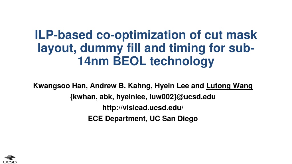
ILP-based co-optimization of cut mask layout, dummy fill and timing for sub- 14nm BEOL technology Kwangsoo Han, Andrew B. Kahng, Hyein Lee and Lutong Wang {kwhan, abk, hyeinlee, luw002}@ucsd.edu http://vlsicad.ucsd.edu/ ECE Department, UC San Diego
Outline Motivation & Related Works Our approach: ILP-based cut mask optimization Post-ILP optimization Experimental results Conclusion and Future work 2
Motivation Self-aligned multiple patterning (SAxP) + Cut process extension cut Final layout Cut masks dummy fill Original layout 1D wires Cut shapes and locations determine dummy wires, end-of-line (EOL) extension of wire segments affect performance Cut mask optimization must understand these effects We propose a step by step co-optimization with EOL extension and dummy fills 3
Related works [Zhang11] proposes shortest path-based approach Improve the printability of cuts No timing-aware optimization Unrealistic rules [Du12] and [Ding14] propose Integer Linear Programming-based approaches Minimize the sum of end-of-line (EOL) extensions A hybrid optimization of cut masks and e-beam lithography No timing-aware optimization No consideration of using multiple cut masks No consideration of dummy fills Our work: co-optimization of (i) cut mask coloring, (ii) design timing and (iii) metal density (dummy fill) considering cut mask layout rules 4
Outline Motivation & Related Works Our approach: ILP-based cut mask optimization Post-ILP optimization Experimental results Conclusion and Future work 5
ILP-based Cut Mask Optimization Definition Minimum cut spacing Metal Extended Metal Cut Mask 1 Forbidden location Cut Mask 2 Metal Extended Metal Metal Cut Mask 1 Forbidden location Cut Mask 1 Forbidden location Objective: Minimize the weighted sum of EOL extensions timing impact due to EOL extension Subject to: Minimum cut spacing: e.g.,110nm C2C Euclidean distance How we assign cuts to different cut masks (color assignment) +more (separating? / merging?) Metal Cut Mask 1 Forbidden location 6
ILP-based Cut Mask Coloring Objective w: weight, e: length of extension Minimize weighted sum of EOL extensions ?? ?? min ???????? ? Subject to c: 0-1 indicator for color assignment x: x-coordinate of cut, G: a big constant 0 ? #cuts Color assignment ?= 1 ?? ?????? ? ? ?? ? ???? Minimum spacing rule ?? ??+ ? 2 ?? + more constraints 7
More Constraints Two choices Separating by at least minimum spacing Merging by vertical alignment mins Metal Extended Metal Cut Mask 1 Add 0-1 variable m to select whether to separate or merge cuts (b) Merging (a) Separating Separate or Merge? m: 0-1 indicator for merging Set A: Separating ?? ??+ ? ? ???? ?? ??+ ? 1 ? 0 Set B: Merging ?? ?? ? 1 ? 0 8
Modeling Timing Impact of a Wire Segment Weights on wire segments are determined based on timing criticality ?? ?? Objective: min ???????? ? Timing criticality net slack = path slack * (stage delay / path delay) net2 Net1 slack = 2.5ps Net2 slack = 2ps Path slack = 10ps Path delay = 200ps Gate1 + net1 = 50ps Gate2 + net2 = 40ps net1 Gate2 Gate1 We sort nets based on net slack, and classify them into different groups In our experiment, we have two groups We assign different weights for different groups The weight values are obtained based on experiments 9
Partitioning-based Distributable Optimization Limitation of ILP-based approach Runtime Split the post-route layout into small clips First iteration: optimize all small clips in parallel Second iteration: optimize the regions (shaded) near the horizontal boundaries Third iteration: optimize the regions (shaded) near the vertical boundaries Vertical boundaries Horizontal boundaries Clip #2 Clip #1 Min spacing X 4 Clip #1 Clip #1 Clip #2 Clip #3 Clip #2 Clip #3 Clip #4 Clip #3 Clip #4 Clip #5 Clip #6 Clip #4 Clip #5 Clip #6 Clip #5 Clip #6 Clip #7 Clip #8 Clip #9 First iteration Second iteration Third iteration 10
Post-ILP Optimization Propose a heuristic for further cut mask optimization Enlarge/insert cuts near wire segments in the descending order of timing-criticality Iterative optimization until the total metal density reaches the minimum metal density Consider the mask density uniformity among different colored masks ILP Solution mins mins mins DefineTargetRegion Candidate cuts on cut mask 1 EnumCandidateCuts mins SelectCuts Candidate cuts on cut mask 2 Cut mask solution when mask density d3 < d2 < d1 (c) Metal Target region Cut Mask 1 Cut Mask 3 N mins mins k min? Cut Mask 2 (a) Y Candidate cuts on cut mask 3 (b) Optimized Solution 11
Overall Flow Routed layout Cut mask optimization (layer by layer) Optimization for each window ILP-based cut mask optimization Design rules - Min cut spacing - #Cut masks ILP Solve multiple windows in parallel formulation ILP solver (CPLEX) Timing/Density-aware post-ILP optimization k min? No Yes Optimized layout 12
Outline Motivation & Related Works Our approach: ILP-based cut mask optimization Post-ILP optimization Experimental results Conclusion and Future work 13
Experimental Setup: Designs and Technologies Designs: ARM Cortex M0, AES (aes cipher top)[OpenCores] Technology Option 1 (N7): 7nm cell library with scaled 28nm BEOL (back-end-of-line) LEF Option 2 (N5): 5nm (scaled 7nm) cell library with scaled 28nm BEOL (back-end-of-line) LEF SP&R tools: Synopsys Design Compiler (synthesis), Cadence Encounter (P&R) min M1 pitch of 28nm node #segments min M2 pitch of 28nm node Design #cells #nets Area (um2) Tech. Util. (%) M2 M3 M4 M5 M6 8994 9048 8272 81 33311 21359 10606 6306 2595 M0 N7 13340 13602 9807 86 46034 29552 16935 10453 4939 AES 8386 8440 7778 76 31881 20934 10534 6194 2547 M0 N5 11650 11912 8596 Scale by 2.5x 81 42819 28176 16223 10480 4960 AES B0 B1 A1 A0 Y OAI22 in 7nm node [OpenCores] http://opencores.com/ 14
Experimental Setup: Design of Experiments Experiment 1: impact of number of cut masks Options C1 to C12 for #cut masks Technology N7 Minimum cut spacing: 4 X minimum M2 pitch Minimum track occupancy: 80% Options for #cut masks C1 #cut masks for M2 M6 2, 1, 1, 1, 1 C2 3, 2, 1, 1, 1 C3 3, 2, 2, 1, 1 Experiment 2: impact of minimum metal density (track occupancy) Minimum track occupancy (80%, 85% 90%) with default setup Technology N7 Minimum cut spacing: 4 X minimum M2 pitch Option C5 for #cut masks C4 3, 2, 2, 2, 1 C5 3, 2, 2, 2, 2 C6 4, 2, 2, 2, 2 C7 4, 3, 2, 2, 2 C8 4, 3, 3, 2, 2 Experiment 3: impact of minimum cut spacing Technology N7 (min cut spacing: 4 X minimum M2 pitch) Technology N5 (min cut spacing: 5 X minimum M2 pitch) Minimum track occupancy: 80% C9 4, 3, 3, 3, 2 C10 4, 3, 3, 3, 3 C11 5, 4, 4, 4, 4 C12 10, 10, 10, 10, 10 15
Experiment 1: Impact of #Cut Masks For Cortex M0 and AES One mask is not enough for a layer C5 (3,2,2,2,2) gives sufficient #cut masks #Cut masks vs Infeasible clips (%) 35 30 Options for #cut masks C1 #cut masks for M2 M6 2, 1, 1, 1, 1 Infeasible Clips (%) 25 20 C2 3, 2, 1, 1, 1 15 C3 3, 2, 2, 1, 1 10 C4 3, 2, 2, 2, 1 5 0 C1 C2 C3 C4 C5 #Cut masks (M2-M6) C6 C7 C8 C9 C10 C11 C12 ARM Cortex M0 AES 16
Experiment 1: Impact of #Cut Masks #Cut masks EOL extension (%) C5 C6 saves 2% for AES (2040 m) and 1% for Cortex M0 (1034 m) (= extended wirelength/original wirelength x 100) Overall % EOL extension 5.00% Overall % EOL extension 4.00% 3.00% 2.00% 1.00% 0.00% C5 C6 C7 #Cut masks (M2-M6) C8 C9 C10 C11 C12 ARM Cortex M0 AES 17
Experiment 1: Impact of #Stages on Critical Path Results for Cortex M0 and AES % EOL extension of Cortex M0 is always lower than AES Worst negative slack (WNS) of Cortex M0 is more impacted by EOL extension and dummy fill than AES Change in WNS of Cortex M0 is up to 23ps worse than that of AES The accumulative effect of the added stage delay Overall % EOL extension Design #stages 50 8 M0 AES Change in WNS due to EOL and dummy fill 5.00% 0 Overall % EOL extension Change in WNS (ns) -0.01 4.00% -0.02 3.00% -0.03 2.00% -0.04 1.00% -0.05 0.00% -0.06 C5 C6 C7 #Cut masks (M2-M6) C8 C9 C10 C11 C12 C5 C6 C7 #Cut masks (M2-M6) C8 C9 C10 C11 C12 ARM Cortex M0 AES ARM Cortex M0 AES 18
Experiment 2: Impact of Minimum Track Occupancy Post-ILP optimization is beneficial to timing Different track occupancy with up to 22ps difference Change in WNS for different minimum track occupancy ARM Cortex M0 AES 0 -0.01 Change in WNS (ns) -0.02 -0.03 -0.04 -0.05 22ps -0.06 18ps -0.07 80% 85% 90% 19
Experiment 3: Impact of Minimum Cut Spacing N5 is more sensitive to #cut masks Wire delay is more dominant than the gate delay Wire resistance increase is greater than the wire capacitance decrease per unit length #Cut masks vs WNS -0.02 -0.025 -0.03 11ps -0.035 WNS (ns) -0.04 -0.045 17ps -0.05 -0.055 -0.06 Min #cut masks Min+1 Min+2 ARM Cortex M0 N7 AES N7 ARM Cortex M0 N5 AES N5 20
Outline Motivation & Related Works Our approach: ILP-based cut mask optimization Post-ILP optimization Experimental results Conclusion and Future work 21
Conclusion ILP-based cut mask optimization Minimize the weighted sum of extensions considering color assignment and cut mask layout rules Timing/Density-aware post-ILP optimization Further cut mask optimization that is aware of timing, minimum metal density and mask density uniformity Experiments in varying contexts give insight into the tradeoff of performance and cost Follow-up works: Use more precise weight assignment in ILP Comparison of the best choice of single cuts vs. the worst/random choice ECO route for infeasible routing clips to reduce the mask cost Co-optimization of routing and cut mask 22


