Combinational Logic Circuits in Electronics
Combinational logic
circuits
powered by jpwebdevelopers
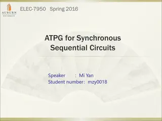
Types of combinational logic
circuits
•
A
d
d
e
r
s
•
S
u
b
t
r
a
c
t
o
r
powered by jpwebdevelopers
Half Adder
Full Adder
Half subtracror
Full subtractor
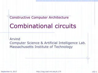
Firstly we discuss about Adder
Definition of adder:
Adders are the combinational logic circuits which are used for adding two or three binary
bits.
Types of Adder:
Half adder
Full adder
powered by jpwebdevelopers
H
A
L
F
A
D
D
E
R
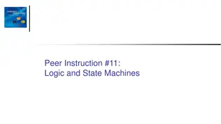
Definition of Half adder:
Half adder add two binary digits
and produces two binary outputs called sum and carry.
•
It generates sum(s) and carry(c) as output.
•
Block Diagram:
powered by jpwebdevelopers
Half adder
Truth table
powered by jpwebdevelopers
K-Map for half adder
powered by jpwebdevelopers
Logic expressions:
s=A’B+AB’
•
Logic Diagram:
powered by jpwebdevelopers
Full Adder
•
F
u
l
l
a
d
d
e
r
h
a
s
t
h
r
e
e
i
n
p
u
t
b
i
t
s
A
,
B
a
n
d
a
d
d
i
t
i
o
n
a
l
c
a
r
r
y
-
i
n
(
i
n
)
•
I
t
i
s
u
s
e
d
t
o
a
d
d
t
h
r
e
e
b
i
t
s
a
n
d
g
e
n
e
r
a
t
e
t
w
o
o
u
t
p
u
t
s
u
m
(
s
)
,
c
a
r
r
y
(
c
)
•
B
l
o
c
k
d
i
a
g
r
a
m
:
s
u
m
I
n
p
u
t
s
o
u
t
p
u
t
s
c
a
r
r
y
powered by jpwebdevelopers
Full adder
T
r
u
t
h
t
a
b
l
e
powered by jpwebdevelopers
K-map
powered by jpwebdevelopers
Logic Diagram
powered by jpwebdevelopers
powered by jpwebdevelopers
T
h
a
n
k
y
o
u
Download ppt’s and handwritten notes
JP Web devolpers
Follow on instagram:-
@jpwebdevelopers
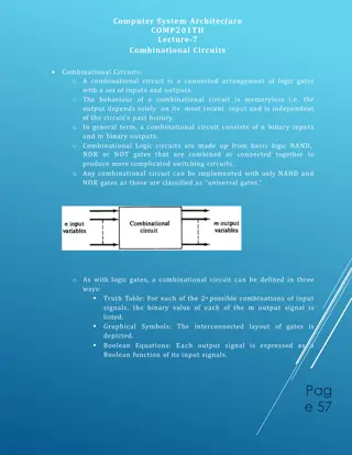
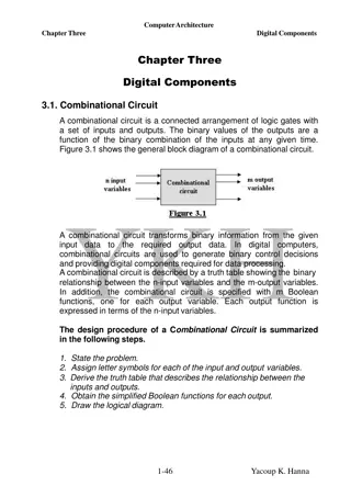
Delve into the world of combinational logic circuits powered by JP Web Developers. From adders to subtractors, half adders to full adders, learn about their types, definitions, truth tables, logic expressions, and more. Unveil the working principles and applications of these essential components for digital electronics design.

Download Presentation

Please find below an Image/Link to download the presentation.
The content on the website is provided AS IS for your information and personal use only. It may not be sold, licensed, or shared on other websites without obtaining consent from the author.If you encounter any issues during the download, it is possible that the publisher has removed the file from their server.
You are allowed to download the files provided on this website for personal or commercial use, subject to the condition that they are used lawfully. All files are the property of their respective owners.
The content on the website is provided AS IS for your information and personal use only. It may not be sold, licensed, or shared on other websites without obtaining consent from the author.
E N D
Presentation Transcript
Combinational logic circuits powered by jpwebdevelopers
Types of combinational logic circuits Adders Subtractor Half Adder Half subtracror Full subtractor Full Adder powered by jpwebdevelopers
Firstly we discuss about Adder Definition of adder: Adders are the combinational logic circuits which are used for adding two or three binary bits. Types of Adder: Half adder Full adder powered by jpwebdevelopers
HALF ADDER Definition of Half adder: Half adder add two binary digits and produces two binary outputs called sum and carry. It generates sum(s) and carry(c) as output. Block Diagram: Half adder powered by jpwebdevelopers
Truth table Input bits output A B sum carry 0 0 0 0 0 1 1 0 1 0 1 0 1 1 0 1 powered by jpwebdevelopers
K-Map for half adder powered by jpwebdevelopers
Logic expressions: s=A B+AB Logic Diagram: powered by jpwebdevelopers
Full Adder Full adder has three input bits A,B and additional carry-in(in) It is used to add three bits and generate two output sum(s),carry(c) Block diagram: sum Inputs outputs carry Full adder powered by jpwebdevelopers
Truth table Inputs bits outputs A B C Sum carry 0 0 0 0 0 0 0 1 1 0 0 1 0 1 0 0 1 1 0 1 1 0 0 1 0 1 0 1 0 1 1 1 0 0 1 1 1 1 1 1 powered by jpwebdevelopers
K-map powered by jpwebdevelopers
Logic Diagram powered by jpwebdevelopers
Thank you Download ppt s and handwritten notes JP Web devolpers Follow on instagram:-@jpwebdevelopers powered by jpwebdevelopers