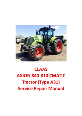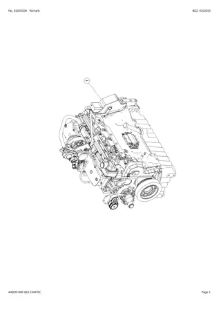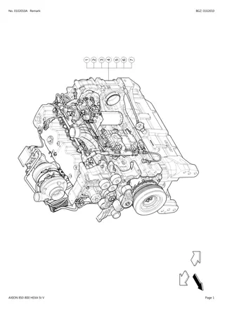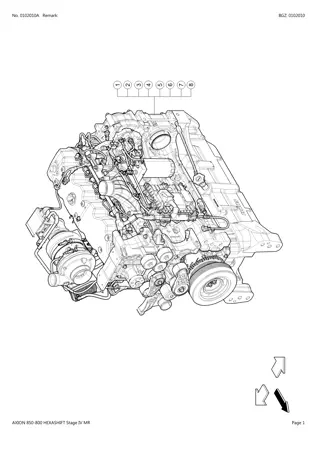
CLAAS AXION 850-810 (Type A09) Tractor Service Repair Manual Instant Download
Please open the website below to get the complete manualnn//
Download Presentation

Please find below an Image/Link to download the presentation.
The content on the website is provided AS IS for your information and personal use only. It may not be sold, licensed, or shared on other websites without obtaining consent from the author. Download presentation by click this link. If you encounter any issues during the download, it is possible that the publisher has removed the file from their server.
E N D
Presentation Transcript
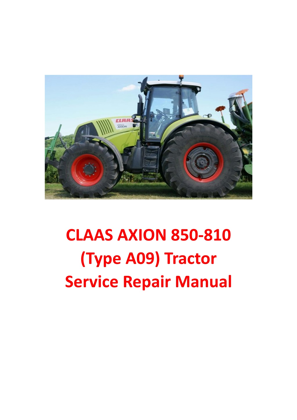
CLAAS AXION 850-810 (Type A09) Tractor Service Repair Manual
General Removing the front axle Warning: The front axle must be raised on stands at the same time as the rear axle if the current operation requires the engine to be started up as the front axle remains engaged when stationary.There is therefore a risk of the tractor moving. The tractor must be immobilised on flat, level ground (in the case of front lifting, raise the arms to maximum height). Apply the handbrake. Disconnect the battery. Chock the rear wheels. Shim the front axle to prevent it from swivelling. Remove the housing and drive shaft. Remove the front wheels. Chock the tractor under the crankcase with stands (shim it as high as possible to facilitate the axle's passage forward). Remove the angular sensor bracket (3 screws). Disconnect the hose couplings from the steering cylinder. Disconnect the hydraulic unit hoses on the left side. Disconnect the harnesses of the hydraulic unit solenoid valves on the left side. Remove the closing panel in the hood nose. Remove the radiator nozzle and the fan by loosening the central nut (Left-hand thread). Position an appropriate device. Set into tension. Remove the 8 screws (A) of the bearings. Remove the front axle. When changing the axle, check the oil levels. According to the intervention on the front axle: drain the axle when removing. 455hsm84 Fig. 7 A 455hsm82 Fig. 8 A 455hsm83 Fig. 9 D1.8 Axion 850-810 10.2010 GB
General Refitting the front axle Sling the front axle using an appropriate means. Place the front axle as to engage the fastening screws (A). Pre-tighten the fastening screws (A) on the front axle at 13 daN m, then tighten to 30 daN m. Refit the parts removed previously. Connect the hoses and the electric cables. Refit the wheels. Remove the props. Top up the levels. 455hsm85 Fig. 10 D1.9 Axion 850-810 10.2010 GB
https://www.ebooklibonline.com Hello dear friend! Thank you very much for reading. Enter the link into your browser. The full manual is available for immediate download. https://www.ebooklibonline.com
Epicycloid reducer Exploded view of the epicyclic reducer 19 18 16 15 7 6 5 6 4 17 14 13 12 11 2 3 1 Fig. 11 455hsm61 Description 1 2 3 4 5 6 7 11 Screw. 12 Crown wheel. 13 Ring gear carrier. 14 Locking ring. 15 Tapered roller bearing. 16 O-ring. 17 Wheel holder hub. 18 Tapered roller bearing. 19 Seal. Plug. Seal. Screw. Planet carrier. Planet gear. Tapered roller bearing. Circlip. Preparation Warning: The front axle must be raised on stands at the same time as the rear axle if the current operation requires the engine to be started up as the front axle remains engaged when stationary.There is therefore a risk of the tractor moving. The tractor must be immobilised on flat, level ground. Apply the handbrake. Chock the rear wheels. Disconnect the battery. Place the tractor on stands. Remove the front wheels. D1.10 Axion 850-810 10.2010 GB
Epicycloid reducer Removing the epicyclic reducer Warning: Perform all the operations below on the 2 front axle reducers. Remove the oil plug (A). Drain the sump. Remove the fastening screws (B) of the planet holder (C). Remove the planet carrier. C B A 455hsm62 Fig. 12 Remove the circlip (D). Use a puller to pull the planets (E). Pull the tapered roller bearings. D E 455hsm63 Fig. 13 Remove the O-ring (F). Loosen and remove the fastening screws (G) of the crown gear holder. F G 455hsm64 Fig. 14 D1.11 Axion 850-810 10.2010 GB
Epicycloid reducer Remove the crown gear holder using two M8 (H) screws. H 455hsm65 Fig. 15 Remove the retainer ring of the crown gear holder to release the crown gear. Remove the wheel holder hub (I) using a puller. I 455hsm66 Fig. 16 Remove the ring seal (J). Remove the outer cages of the two tapered roller bearings. J 455hsm67 Fig. 17 D1.12 Axion 850-810 10.2010 GB
Epicycloid reducer Refitting the epicyclic reducer Warning: Perform all the operations below on the 2 front axle reducers. Push the outer cages fully using tool n 60 0500 656 8. Start with a wrench to center the outer cages, then finish with a press. Place the bearing (inside the wheel holder hub). Place the sealing bush (B) in its housing using tool n 60 0500 656 8 (place the centrer and cover to engage at the right dimension). Start with a wrench to center the sealing bush, then finish with a press. Beware the fitting direction of the bush ! Ensure the 9 0,1 mm size is applied.Check the sealing bush is uniform. 455hsm72 Fig. 18 Fit the wheel holder hub against the joint. Fit the bearing fully pushed. Assemble the crown gear (C), retainer ring (D), and crown gear holder (E). Fit the assembly fully pushed against the wheel holder hub. Smear the fastening screws with Loctite (242). Cross-tighten at 7,2 0,4 daN m. B 455hsm68 Fig. 19 D C E 455hsm69 Fig. 20 D1.13 Axion 850-810 10.2010 GB
Epicycloid reducer Fit the lower tapered roller bearings using tool n 60 0500 665 1. Caution ! The lower tapered roller bearings have a rounding on the level of the bore. Engage the stallites (F) with the overthickness turned upwards. Engage the upper tapered roller bearings. Place the machined side of the retainer rings towards the bearings. F 455hsm70 Fig. 21 Replace the O-rings. Engage the planet holder into the crown gear holder. Place 2 screws (G) in the holes available. Tighten gradually while the planet holder engages in the crown gear holder. Swivel the assembly while pushing on the planet holder. Remove the 2 screws, place those planned. Tighten to 5 2 daN m. G 455hsm71 Fig. 22 Top up the oil. Quantity: 2 litres per side. Screw the oil plugs at 9 daN m. D1.14 Axion 850-810 10.2010 GB
Joint unit Exploded view 19 16 15 13 12 1 55 11 2 6 3 7 8 9 10 23 14 25 26 12 13 16 19 455hsm19 Fig. 23 Description 1 Sleeve. 2 Plain bush. 3 Seal. 6 Plain bush. 7 Circlip. 8 Bearing. 9 Washer. 10 Circlip. 11 Bearing. 12 Spacer. 13 Plain bush. 14 Bearing. 15 Shim. 16 Joint bracket. 19 Screw. 23 Steering nuckle pivot. 25 Screw. 26 Nut. 55 Wheel shaft. Preparation to removing the joint box Apply the handbrake. Chock the rear wheels. Disconnect the battery. Place the tractor on stands. Remove the front wheels. Warning: The front axle must be raised on stands at the same time as the rear axle if the current operation requires the engine to be started up as the front axle remains engaged when stationary.There is therefore a risk of the tractor moving. The tractor must be immobilised on flat, level ground. D1.15 Axion 850-810 10.2010 GB
Joint unit Removing the joint box Remove the safety pin (A) in the steering bars, then nut (B). Pull the ball socket (C) out of the joint using a socket puller. C B A 455hsm86 Fig. 24 451hsm08 Fig. 25 Fit the shackles in the holes available (D). Remove the joint supports. Remove the gearshift towers. D Note: The wheel shaft comes with it. 455hsm87 Fig. 26 D1.16 Axion 850-810 10.2010 GB
Joint unit Dismantling A B On the joint supports: Remove the bearings. Remove the sealing bushes. On the joint box: Remove the planet holder cover and the crown gear holder. Remove the retaining ring (A). Remove the washer (B). Pull the the wheel shaft. 455hsm20 Fig. 27 Pull the sealing bush (C) using an internal puller. Remove the elastic bush. Extract the bearing (D). C D 455hsm21 Fig. 28 D1.17 Axion 850-810 10.2010 GB
Joint unit On the axle cover: Pull the outer cages of the bearings using an internal uller. Pull the sealing bush (E). Pull the smooth bush (F). Beware the installation direction ! E F 455hsm22 Fig. 29 455hsm23 Fig. 30 Refitting On the axle cover: Lubricate the smooth bush (G) and its housing. Insert it using tool n 60 0500 656 4. G 455hsm24 Fig. 31 D1.18 Axion 850-810 10.2010 GB
Joint unit Lubricate and fit onto tool n 60 0500 656 4 the sealing bush (H), then insert it into its housing. Beware the installation direction ! H 455hsm25 Fig. 32 Lubricate and fit the external cages of the bearings with tool n 77 0138 854 7, check that they are fully pushed. 455hsm93 Fig. 33 On the casing : Lubricate and fit the bearing (I) in its housing. Fit the circlip. I 455hsm26 Fig. 34 D1.19 Axion 850-810 10.2010 GB
Joint unit Lubricate the external surface of the sealing bush (J). Fit it in its housing. J 455hsm27 Fig. 35 Lubricate the tip of the wheel shaft. Fit the shaft in the joint box. 455hsm28 Fig. 36 Fit the washer (K), then the retainer ring (L). Refit the crown gear holder. Tighten at 7,2 0,4 daN m. Refit the cover. Tighten to 5 0,2 daN m. K L 455hsm29 Fig. 37 D1.20 Axion 850-810 10.2010 GB
Suggest: For more complete manuals. Please go to the home page. https://www.ebooklibonline.com If the above button click is invalid. Please download this document first, and then click the above link to download the complete manual. Thank you so much for reading
Joint unit Refit the joint box Sling the joint box. Grease the sealing bush before engaging the shaft in the tube. Refit the joint box onto the tube. 455hsm88 Fig. 38 Grease the housing of the lower joint support (G). Lubricate and fit the sealing bush and the bearing on the support. Beware the fitting direction of the sealing bush ! Fit the lower joint support in its housing. Coat the screws with Loctite (242). Tighten to 19,2 1 daN m. G 455hsm89 Fig. 39 Grease the housing of the upper joint support (H). Lubricate and fit the sealing bush and the bearing on the support. H Beware the fitting direction of the sealing bush ! 455hsm90 Fig. 40 D1.21 Axion 850-810 10.2010 GB
Joint unit Ensure you properly center the sensor (I) in the axis (J) fitted in the upper left joint support under the cover (K). Implement the shimming. Grease the support. Coat the screws with Loctite (242). Tighten at 19,2 1 daN m. Fit the steering bar knuckle. Tighten at 18 1 daN m. Fit a new safety pin. Fit the planet holder cover onto the wheel holder hub. Tighten at 5 0,2 daN m. K J Note: You can fit the sensor finger at the end. Connect the battery. Refit the wheels. Remove the props. Calibrate the steering sensor "B117" (See M tadiag 2007 manual). 455hsm91 Fig. 41 I J 455hsm92 Fig. 42 D1.22 Axion 850-810 10.2010 GB
https://www.ebooklibonline.com Hello dear friend! Thank you very much for reading. Enter the link into your browser. The full manual is available for immediate download. https://www.ebooklibonline.com

