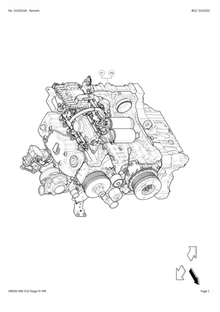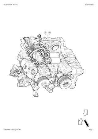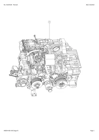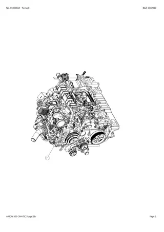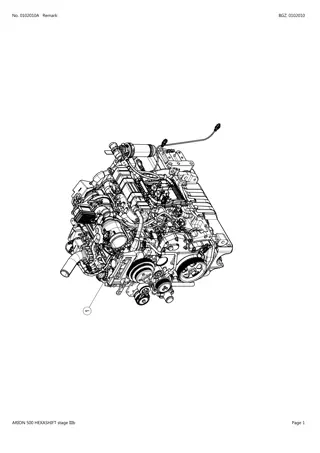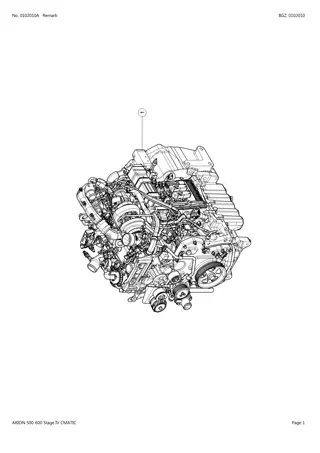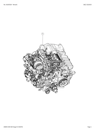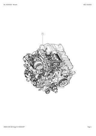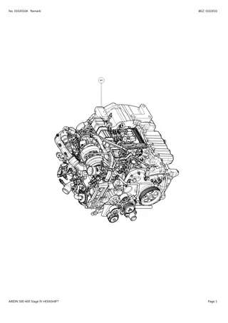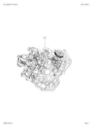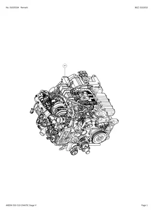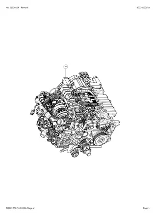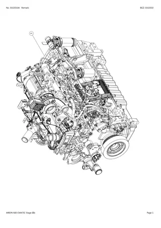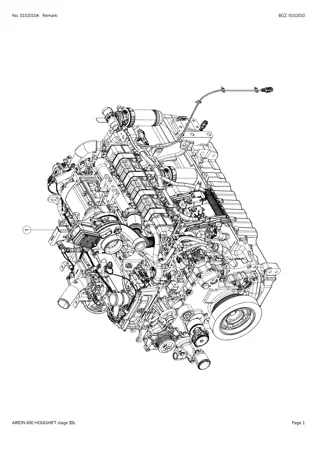
CLAAS ARION 550-530 (Engine) Tractor Service Repair Manual Instant Download
Please open the website below to get the complete manualnn//
Download Presentation

Please find below an Image/Link to download the presentation.
The content on the website is provided AS IS for your information and personal use only. It may not be sold, licensed, or shared on other websites without obtaining consent from the author. Download presentation by click this link. If you encounter any issues during the download, it is possible that the publisher has removed the file from their server.
E N D
Presentation Transcript
ARION 550-530 Repair manual 01-Engine
SPEZIAWERKZEUG SPECIAL TOOL OUTIL SPECIAL REFERENCE IM DOKUMENT REFERENCE IN THE DOCUMENT REFERENCE DANS LE DOCUMENT REFERENZ CLAAS CLAAS REFERENCE REFERENCE CLAAS J D G 1 1 2 0 5 1 0 0 5 7 4 1 0 1 6 JDE83 JDG820 60 0500 550 1 (4.cyl) 60 0500 552 8 (6.cyl) 00 1147 384 0 JDG11206 00 1147 382 0 JDG11186 (D) 00 1135 452 0 JD254A
SPEZIAWERKZEUG SPECIAL TOOL OUTIL SPECIAL REFERENCE IM DOKUMENT REFERENCE IN THE DOCUMENT REFERENCE DANS LE DOCUMENT REFERENZ CLAAS CLAAS REFERENCE REFERENCE CLAAS 00 1147 378 0 JDG739B 60 0500 551 7 JDG680 60 0500 553 4 JDG954B : - JDG954-1 - JDG954-2 77 1113 251 7 JDG954B : - JDG954-5 - JDG954-6 - JDG954-7 - JDG954-8 60 0500 557 3 (4.cyl) JDG1517 60 0500 551 4 JDG1560
https://www.ebooklibonline.com Hello dear friend! Thank you very much for reading. Enter the link into your browser. The full manual is available for immediate download. https://www.ebooklibonline.com
SPEZIAWERKZEUG SPECIAL TOOL OUTIL SPECIAL REFERENCE IM DOKUMENT REFERENCE IN THE DOCUMENT REFERENCE DANS LE DOCUMENT REFERENZ CLAAS CLAAS REFERENCE REFERENCE CLAAS 00 1138 374 0 JDG1649A 60 0500 559 4 JDG2074 00 1147 379 0 JDG11184 00 1147 380 0 JDG11185 00 1147 690 0 JT30040B
Introduction Foreword Section 05 covers other materials needed to do the job. This repair manual covers the 4045 <130kW PowerTech engines for Interim Tier 4/Stage III B platform. Section 06 details all specifications, wear tolerances, torque values, and contains the wiring diagrams. This manual is written for an experienced technician. Essential tools required in performing certain service work are identified in this manual. This manual contains SI Metric units of measure followed immediately by the U.S. customary units of measure. Most hardware on these engines is metric sized. Live With Safety: Read the safety messages in the introduction of this manual and the cautions presented throughout the text of the manual. Read each block of material completely before performing service to check for differences in procedures or specifications. Follow only the procedures that apply to the component you are working on. CAUTION: This is the safety-alert symbol. When you see this symbol on the machine or in this manual, be alert to the potential for personal injury. Component Technical Manuals are concise service guides for specific components. Component Technical Manuals are written as stand-alone manuals covering multiple machine applications. Information in this manual is organized in sections and sub divided into groups. Fundamental service information is available from other sources covering basic theory of operation, fundamentals of troubleshooting, general maintenance, and basic type of failures and their causes. Section 01 covers the safety measures to follow while repairing the engine; engine identification features, engine emission and application details, and information about the fuels, lubricants, and coolants. CALIFORNIA PROPOSITION 65 WARNING Diesel engine exhaust and some of its constituents are known to the State of California to cause cancer, birth defects and other reproductive harm. Section 02 covers the repair and adjustment procedures. Section 03 explains the theory of operation of each system. Section 04 is the diagnostics section that provides troubleshooting procedures to find problems. PowerTech is a trademark of Deere & Company BK34394,0000E6E -19-25JAN11-1/1 Record of Changes Block Title New manual Section-Group Group Title Comment BK34394,0000E6F -19-25JAN11-1/1 4.5 L Interim Tier 4 Diesel Engines Below CTM114619 (29AUG11) 130kW (174 hp) 101011 PN=2
Introduction 4045 <130kW PowerTech PVX Engine Interim Tier 4/Stage III B RG19914 UN 28JAN11 RG19915 UN 28JAN11 3/4 right front view 4045HFC93 Engine 3/4 left front view 4045HFC93 Engine RG19916 UN 28JAN11 RG19917 UN 28JAN11 3/4 left rear view 4045HFC93 Engine 3/4 right rear view 4045HFC93 Engine PowerTech is a trademark of Deere & Company BK34394,0000E70 -19-01FEB11-2/2 4.5 L Interim Tier 4 Diesel Engines Below CTM114619 (29AUG11) 130kW (174 hp) 101011 PN=4
Introduction Definition of Terms Actuator A device controlled by the ECU to perform a certain function. Analog Signal which has a continuous range of possible voltages, usually 0 V (low) to 24 V (high). Application Either a movable or stationary piece of equipment that the engine is placed in. Applications include, Tractors, Harvesters, Loaders, Irrigation Pumps, Generator Sets, and others. BAP Barometric Air Pressure. Pressure of the atmosphere (atmospheric pressure). Boost Pressurized air in the intake manifold. CAC Charge Air Cooler. Cools the compressed air from the turbine before it enters the intake manifold. CAN Controller Area Network. The network on applications that allows communication between the engine control unit and some components. Circuit Power Power supplied to a device for use by its internal component circuits. Crankshaft Position Sensor Used to determine the angular position and velocity of the crankshaft in the 360 field of rotation. Digital A signal which consists of only two levels of voltage usually 0 V (low) to 24 V (high). DOC Diesel Oxidation Catalyst. Part of the exhaust filter or aftertreatment device. Used to help reduce emissions. DPF Diesel Particulate Filter. Part of the exhaust filter or aftertreatment device. Used to help reduce emissions. DTC Diagnostic Trouble Code. A code that is stored in ECU memory when it detects a problem in the electronic control system. There are two types of codes: Active and Stored. These codes are displayed on monitor panels and can be recalled by the service tool. ECT Engine Coolant Temperature. The temperature of the engine coolant. ECU Engine Control Unit. Computer that controls the fuel, air, and ignition systems on the engine. EGR Exhaust Gas Recirculation. Used to help reduce emissions. EI An Electronic Injector that is regulated by the ECU to control the proper amount of fuel on High-Pressure Common rail fuel systems. EOL This is the abbreviation for End of Line which is where the ECU gets programmed at the factory. EUI An Electronic Unit Injector that is regulated by the ECU to control the proper amount of fuel on non-High-Pressure Common rail fuel systems. FMI Failure Mode Identifier. The second part of a two-part code that identifies control system fault codes according to the J1939 standard. This two-digit code identifies the type of failure that has occurred. The first half of the code is the Suspect Parameter Number (SPN). H-Bridge Circuits in the ECU set up in an H-configuration. This allows for current to be reversed to drive DC motors forward and reverse. HPCR High-Pressure Common-Rail. A device that distributes high-pressure fuel to the injectors. Input This identifies a signal as an input to a device or control unit. J1939 The Society of Automotive Engineers (SAE) standard for communication between the electronic control units on heavy-duty vehicles, both on- and off-highway. Continued on next page BK34394,0000E72 -19-08AUG11-1/2 4.5 L Interim Tier 4 Diesel Engines Below CTM114619 (29AUG11) 130kW (174 hp) 101011 PN=6
Introduction JDCP John Deere Custom Performance Program allows the customer to select software features and feature combinations prior to loading the software into the ECU. It is also one way by which embedded software is managed and updated in control units without removal of the control unit from the machine. JDPS John Deere Power Systems. MAP Manifold Air Pressure. The pressure of the air in the intake manifold, sometimes referred to as boost pressure. MAT Manifold Air Temperature. The temperature of the air in the intake manifold. Meter Zero This is the value the multimeter reads in the ohm position, when the meter lead tips are held together. Mis-pin An incorrect placement of male pins or female sockets within an electrical connector. Also known as an incorrect swapping of wires and terminals. OOR Out-of-Range. The signal received by the ECU is out of the expected range of the device. OORH Out-of-Range High. Signal sensed by the ECU is higher than the component can produce (outside of acceptable limit). For some circuit types, this could be caused by an open input wire, an open ground wire, or an input wire shorted to a voltage higher than the ECU expects (+ battery). OORL Out-of-Range Low. Signal sensed by the ECU is lower than the component can produce (outside of acceptable limits). For some circuit types, this could be caused by an input wire or circuit power wire shorted to ground. Output This identifies a signal as an output from a device or control unit. Pin A style of terminal that makes the electrical connection to a connector. Also called a male terminal. PWM Pulse Width Modulation. A digital electronic signal of a fixed frequency. The on-time of the signal is increased or decreased (modulated) to indicate a change in condition. RAM Random Access Memory. The portion of the computer memory within the ECU that is used when the ECU is running. All data in this memory is lost when the ECU is OFF . Socket A style of terminal that makes the electrical connection to a connector. Also called a female terminal or receptacle. Suction Control Valve Suction Control Valve regulates the amount of fuel that the high-pressure fuel pump supplies the HPCR. SDS Software Delivery System. Used by JDPS to maintain software and programming records. Sensor Device used by the ECU to monitor various engine parameters. SPN Suspect Parameter Number. The first half of a two-part code that identifies control system fault codes according to the J1939 Standard. The SPN identifies the system or component that has the failure. The second half of the code is the Failure Mode Identifier (FMI). TDC Top Dead Center. Point of uppermost piston travel. Throttle Rate How quickly the ECU changes the engine fuel rate in response to a throttle signal. Acceleration and deceleration rates are adjustable. Availability of throttle rates may vary, depending on engine model. Trim Options Options that can be enabled or disabled in the ECU programming, such as throttle selection, torque adjustment, governor gains, derates, and shutdowns, and others. TWV Two-Way Valve. A component in the Electronic Injector (EI). VGT Variable Geometry Turbo. Used to reduce emissions. WIF Water-In-Fuel. The WIF sensor sends a signal to the ECU when water is detected in the fuel. BK34394,0000E72 -19-08AUG11-2/2 4.5 L Interim Tier 4 Diesel Engines Below CTM114619 (29AUG11) 130kW (174 hp) 101011 PN=7
Section 01 General Information Contents Page Page Commercial Engine Designation.................01-001-4 Group 000 Safety Avoid Harmful Asbestos Dust......................01-000-1 Avoid Heating Near Pressurized Fluid Lines...............................................01-000-1 Avoid High-Pressure Fluids.........................01-000-1 Avoid Hot Exhaust.......................................01-000-2 Construct Dealer-Made Tools Safely.......................................................01-000-2 Dispose of Waste Properly..........................01-000-2 Exhaust Filter Cleaning ...............................01-000-3 Follow Safety Instructions............................01-000-3 Handle Agricultural Chemicals Safely.......................................................01-000-4 Handle Chemical Products Safely................01-000-4 Handle Fluids Safely Avoid Fires.........................................................01-000-5 Handle Fuel Safely Avoid Fires.................01-000-5 Handle Starting Fluid Safely........................01-000-5 Handling Batteries Safely............................01-000-6 Illuminate Work Area Safely........................01-000-6 Install All Guards .........................................01-000-7 Live With Safety...........................................01-000-7 Practice Safe Maintenance..........................01-000-8 Prepare for Emergencies.............................01-000-8 Prevent Acid Burns......................................01-000-9 Prevent Battery Explosions .........................01-000-9 Prevent Machine Runaway........................01-000-10 Protect Against High Pressure Spray.....................................................01-000-10 Protect Against Noise................................01-000-10 Recognize Safety Information ................... 01-000-11 Remove Paint Before Welding or Heating.................................................. 01-000-11 Replace Safety Signs................................ 01-000-11 Service Cooling System Safely .................01-000-12 Service Machines Safely...........................01-000-12 Stay Clear of Rotating Drivelines...............01-000-12 Understand Signal Words..........................01-000-13 Use Proper Lifting Equipment....................01-000-13 Use Proper Tools.......................................01-000-13 Wait Before Opening High-Pressure Fuel System...................01-000-14 Wear Protective Clothing...........................01-000-14 Work in Clean Area ...................................01-000-14 Work In Ventilated Area.............................01-000-15 Group 002 Fuels, Lubricants, and Coolants Diesel Fuel...................................................01-002-1 Handling and Storing Diesel Fuel................01-002-1 Lubricity of Diesel Fuel................................01-002-2 Testing Diesel Fuel......................................01-002-2 Biodiesel Fuel..............................................01-002-3 Minimizing the Effect of Cold Weather on Diesel Engines.....................01-002-4 Diesel Engine Oil.........................................01-002-5 John Deere Break-In Plus Engine Oil................................................01-002-5 Engine Oil and Filter Service Intervals...................................................01-002-6 Oil Filters .....................................................01-002-6 Grease.........................................................01-002-6 Lubricant Storage........................................01-002-6 Mixing of Lubricants.....................................01-002-7 Alternative and Synthetic Lubricants................................................01-002-7 OILSCAN and COOLSCAN .................01-002-7 Heavy Duty Diesel Engine Coolant....................................................01-002-8 Supplemental Coolant Additives..................01-002-8 Operating in Warm Temperature Climates...................................................01-002-9 Testing Diesel Engine Coolant.....................01-002-9 Drain Intervals for Diesel Engine Coolant..................................................01-002-10 John Deere COOL-GARD II Coolant Extender...................................01-002-10 Additional Information About Diesel Engine Coolants and John Deere COOL-GARD II Coolant Extender................................... 01-002-11 Group 001 Engine Identification Information Engine Identification Plate Information...............................................01-001-1 OEM Engine Option Code Label.................01-001-2 Information Relative to Emissions Regulations..............................................01-001-3 Emissions Control System Certification Label....................................01-001-4 01-1 4.5 L Interim Tier 4 Diesel Engines Below CTM114619 (29AUG11) 130kW (174 hp) 101011 PN=1
Group 000 Safety Avoid Harmful Asbestos Dust Avoid breathing dust that may be generated when handling components containing asbestos fibers. Inhaled asbestos fibers may cause lung cancer. Components in products that may contain asbestos fibers are brake pads, brake band and lining assemblies, clutch plates, and some gaskets. The asbestos used in these components is usually found in a resin or sealed in some way. Normal handling is not hazardous as long as airborne dust containing asbestos is not generated. TS220 UN 23AUG88 Avoid creating dust. Never use compressed air for cleaning. Avoid brushing or grinding material containing asbestos. When servicing, wear an approved respirator. A special vacuum cleaner is recommended to clean asbestos. If not available, apply a mist of oil or water on the material containing asbestos. Keep bystanders away from the area. DX,DUST -19-15MAR91-1/1 Avoid Heating Near Pressurized Fluid Lines Flammable spray can be generated by heating near pressurized fluid lines, resulting in severe burns to yourself and bystanders. Do not heat by welding, soldering, or using a torch near pressurized fluid lines or other flammable materials. Pressurized lines can accidentally burst when heat goes beyond the immediate flame area. TS953 UN 15MAY90 DX,TORCH -19-10DEC04-1/1 Avoid High-Pressure Fluids Escaping fluid under pressure can penetrate the skin causing serious injury. Avoid the hazard by relieving pressure before disconnecting hydraulic or other lines. Tighten all connections before applying pressure. X9811 UN 23AUG88 Search for leaks with a piece of cardboard. Protect hands and body from high-pressure fluids. If an accident occurs, see a doctor immediately. Any fluid injected into the skin must be surgically removed within a few hours or gangrene may result. Doctors unfamiliar with this type of injury should reference a knowledgeable medical source. Such information is available in English from Deere & Company Medical Department in Moline, Illinois, U.S.A., by calling 1-800-822-8262 or +1 309-748-5636. DX,FLUID -19-20AUG09-1/1 01-000-1 4.5 L Interim Tier 4 Diesel Engines Below CTM114619 (29AUG11) 130kW (174 hp) 101011 PN=13
Safety Avoid Hot Exhaust Servicing machine or attachments with engine running can result in serious personal injury. Avoid exposure and skin contact with hot exhaust gases and components. Exhaust parts and streams become very hot during operation. Exhaust gases and components reach temperatures hot enough to burn people, ignite, or melt common materials. RG17488 UN 21AUG09 DX,EXHAUST -19-20AUG09-1/1 Construct Dealer-Made Tools Safely Faulty or broken tools can result in serious injury. When constructing tools, use proper, quality materials, and good workmanship. Do not weld tools unless you have the proper equipment and experience to perform the job. LX1016749 UN 01JUL97 DX,SAFE,TOOLS -19-10OCT97-1/1 Dispose of Waste Properly Improperly disposing of waste can threaten the environment and ecology. Potentially harmful waste used with John Deere equipment include such items as oil, fuel, coolant, brake fluid, filters, and batteries. TS1133 UN 26NOV90 Use leakproof containers when draining fluids. Do not use food or beverage containers that may mislead someone into drinking from them. Do not pour waste onto the ground, down a drain, or into any water source. Air conditioning refrigerants escaping into the air can damage the Earth s atmosphere. Government regulations may require a certified air conditioning service center to recover and recycle used air conditioning refrigerants. Inquire on the proper way to recycle or dispose of waste from your local environmental or recycling center, or from your John Deere dealer. DX,DRAIN -19-03MAR93-1/1 01-000-2 4.5 L Interim Tier 4 Diesel Engines Below CTM114619 (29AUG11) 130kW (174 hp) 101011 PN=14
Section 02 Repair and Adjustments Contents Page Page Rocker Arm Shaft Assembly Inspect and Assemble...........................02-020-28 Rocker Arm Shaft Carrier Assembly Installation.........................................02-020-31 Valve Assembly Removal .....................02-020-35 Valve Cleaning and Inspection..............02-020-36 Valve Clearance Adjustment.................02-020-37 Valve Grinding.......................................02-020-40 Valve Lift Check....................................02-020-40 Valve Measurement..............................02-020-43 Valve Recess Measurement.................02-020-44 Valve Assembly Reassemble................02-020-45 Valve Guide Cleaning ...........................02-020-46 Valve Guide Installation ........................02-020-47 Valve Guide Measurement....................02-020-48 Valve Guide Removal ...........................02-020-48 Valve Retainer, Valve Bridges, and Valve Retainer Locks Inspection..............................................02-020-49 Valve Seat Cleaning and Inspection..............................................02-020-49 Valve Seat Grinding..............................02-020-50 Valve Seat Measurements....................02-020-51 Valve Seat Inserts Installation...............02-020-52 Valve Seat Inserts Removal..................02-020-53 Valve Spring Inspection ........................02-020-54 Valve Spring Measurement...................02-020-54 Group 010 Engine Rebuild Check and Service Cooling System.....................................................02-010-1 Check Crankcase Vent System...................02-010-1 Check Electrical System..............................02-010-2 Check Exhaust System ...............................02-010-2 Clean Engine...............................................02-010-3 Disconnect Turbocharger Oil Supply Line..............................................02-010-3 Engine Break-In Guidelines.........................02-010-3 Engine Overhaul Guidelines........................02-010-3 Engine Repair Stand ...................................02-010-4 General Tune-Up Recommenda- tions.........................................................02-010-4 Install Adapters on Repair Stand.................02-010-5 Lifting Procedure .........................................02-010-6 Mount Engine on Repair Stand ...................02-010-7 Perform Engine Break-In.............................02-010-7 Safety Precautions ......................................02-010-8 Group 020 Cylinder Head and Valves Repair and Adjustments Cylinder Block Top Deck Cleaning and Inspection..........................02-020-1 Cylinder Head Cleaning and Inspection................................................02-020-1 Cylinder Head Installation.......................02-020-2 Cylinder Head Flatness Check................02-020-8 Cylinder Head Removal..........................02-020-9 Cylinder Head Thickness Measurement......................................... 02-020-11 Cylinder Head Gasket Inspection..............................................02-020-12 Fuel Injector Sleeves Installation .............................................02-020-13 Fuel Injector Sleeves Removal..............02-020-14 Glow Plug Installation ...........................02-020-15 Glow Plug Removal ..............................02-020-17 Glow Plug Bore Cleaning and Inspection..............................................02-020-17 OCV Pressure Relief Valve Maintenance..........................................02-020-18 Push Rod Cleaning and Inspection..............................................02-020-18 Rocker Arm Carrier Inspection..............02-020-19 Rocker Arm Cover Inspection...............02-020-19 Rocker Arm Cover Installation..............02-020-19 Rocker Arm Cover Removal.................02-020-23 Rocker Arm Cover Vent Tube Inspection..............................................02-020-26 Rocker Arm Shaft Tear Down ...............02-020-27 Group 030 Cylinder Block, Liners, Pistons and Rods Complete Final Assembly............................02-030-1 Connecting Rod Center-to-Center Bore Measurement...........................................02-030-2 Connecting Rod General Information...............................................02-030-3 Connecting Rod and Cap Inspection................................................02-030-4 Connecting Rod Bearing Inspection and Measurement..................02-030-5 Connecting Rod Bearing Inspection and Measurement (Rod and Crankshaft in Engine)....................................................02-030-6 Connecting Rod Cap Screw Torque Procedure....................................02-030-7 Connecting Rod Pin Bore Cleaning and Inspection..........................02-030-7 Cylinder Block Cleaning and Inspection................................................02-030-8 Cylinder Block Tear Down.....................02-030-12 Continued on next page 02-1 4.5 L Interim Tier 4 Diesel Engines Below CTM114619 (29AUG11) 130kW (174 hp) 101011 PN=1
Contents Page Page Cylinder Block Components Measurement.........................................02-030-13 Cylinder Block O-ring Installation .............................................02-030-14 Cylinder Block, Piston, and Rod Troubleshooting Guide ..........................02-030-15 Cylinder Liner Cleaning.........................02-030-15 Cylinder Liner Flange Measurement.........................................02-030-16 Cylinder Liner Installation......................02-030-17 Cylinder Liner Removal.........................02-030-18 Cylinder Liner Standout Measurement.........................................02-030-20 Cylinder Liner Visual Inspection..............................................02-030-21 Cylinder Liner O-ring Bore Cleaning ................................................02-030-22 Cylinder Liner Packing Installation .............................................02-030-22 Piston Cleaning.....................................02-030-23 Piston Visual Inspection........................02-030-23 Piston and Connecting Rod Assembly Installation........................02-030-24 Piston and Connecting Rod Assembly Removal ...........................02-030-25 Piston and Connecting Rod Assembly Re-assemble ....................02-030-27 Piston and Connecting Rod Assembly Tear Down........................02-030-28 Piston Cooling Orifice Cleaning and Inspection.......................................02-030-28 Piston Cooling Orifice Installation .............................................02-030-29 Piston Cooling Orifice Removal ................................................02-030-30 Piston Height Measurement..................02-030-30 Piston Pin and Bore Inspection..............02-030-31 Piston Pin and Bushing Inspection..............................................02-030-32 Piston Pin Bushing Installation..............02-030-33 Piston Pin Bushing Removal.................02-030-34 Piston Protrusion Measurement.........................................02-030-35 Piston Rings Installation........................02-030-36 Piston Skirt Measurement.....................02-030-36 Piston to Liner Clearance Check ....................................................02-030-37 Crankshaft Belt-Driven Auxiliary Drive Removal ....................................02-040-6 Crankshaft Front Oil Seal Installation ...............................................02-040-7 Crankshaft Front Oil Seal Removal ..................................................02-040-8 Crankshaft Gear Installation ...................02-040-9 Crankshaft Gear Removal ....................02-040-10 Crankshaft Grinding Guidelines..............................................02-040-10 Crankshaft Main Bearing Caps Installation ............................................. 02-040-11 Crankshaft Main Bearing Cap Line Bore Specs....................................02-040-12 Crankshaft Main Bearing Caps Removal ................................................02-040-12 Crankshaft Rear Oil Seal Installation .............................................02-040-13 Crankshaft Rear Oil Seal Removal ................................................02-040-14 Crankshaft Thrust Bearing Inspection..............................................02-040-15 Crankshaft Timing Wheel Installation .............................................02-040-16 Crankshaft Timing Wheel Removal ................................................02-040-16 Crankshaft Pulley Installation................02-040-17 Crankshaft Pulley Removal...................02-040-19 Flywheel Inspection ..............................02-040-20 Flywheel Installation..............................02-040-20 Flywheel Removal.................................02-040-21 Flywheel Face Flatness Check..............02-040-21 Flywheel Housing Installation ...............02-040-22 Flywheel Housing Removal ..................02-040-24 Flywheel Pilot Bearing Bore Concentricity Check...............................02-040-24 Flywheel Ring Gear Installation .............................................02-040-25 Flywheel Ring Gear Removal...............02-040-25 Measure Assembled ID of Bearings and OD of Crankshaft Journals..............02-040-26 Open Crankshaft Ventilation System Inspection.............................02-040-27 Open Crankcase Ventilation System Installation............................02-040-27 Open Crankcase Ventilation System Removal...............................02-040-29 Group 040 Crankshaft, Main Bearings and Flywheel Check Main Bearing Oil Clearance................................................02-040-1 Crankshaft End Play Check....................02-040-1 Crankshaft Grinding Specs.....................02-040-2 Crankshaft Inspection.............................02-040-2 Crankshaft Installation ............................02-040-3 Crankshaft Removal ...............................02-040-5 Crankshaft Belt-Driven Auxiliary Drive Installation .................................02-040-6 Group 050 Camshaft, Balancing Shaft, and Timing Gear Train Repair and Adjustment Balancer Shaft Bushing Replacement ...........................................02-050-1 Balancer Shaft Installation......................02-050-1 Balancer Shaft Measure End Play..........................................................02-050-3 Balancer Shaft Removal.........................02-050-4 Balancer Shaft Visual Inspection and Measurement....................................02-050-5 Continued on next page 02-2 4.5 L Interim Tier 4 Diesel Engines Below CTM114619 (29AUG11) 130kW (174 hp) 101011 PN=2
Contents Page Page Balancer Shaft and Lower Idler Gear Timing ........................................02-050-6 Balancer Shaft Gear Check and Replace Components..............................02-050-8 Balancer Shaft Thrust Plate Measure Clearance and Thickness ................................................02-050-9 Camshaft Installation ..............................02-050-9 Camshaft Removal ...............................02-050-10 Camshaft Visual Inspection .................. 02-050-11 Camshaft and Upper Idler Gear Timing.................................................... 02-050-11 Camshaft Bushing Replacement .........................................02-050-13 Camshaft Gear Inspection....................02-050-14 Camshaft Gear-Driven Auxiliary Drive Cover Installation.....................02-050-15 Camshaft Gear-Driven Auxiliary Drive Cover Removal........................02-050-15 Camshaft Journals Measurement.........................................02-050-16 Camshaft Lobes Height Measurement.........................................02-050-17 Camshaft Thrust Plate Measure Clearance and Thickness......................02-050-17 Front Plate Installation..........................02-050-18 Front Plate Removal.............................02-050-19 Idler Gears Measure End Play..............02-050-20 Lower Idler Gear Check and Replace Components............................02-050-20 Lower Idler Gear Installation.................02-050-21 Timing Gear Cover Installation..............02-050-22 Timing Gear Cover Removal ................02-050-24 Timing Gears Check Backlash..............02-050-25 Upper Idler Gear Check and Replace Components............................02-050-26 Belt Tensioner Removal..........................02-070-2 Belt Tensioner Spring Tension Check ......................................................02-070-3 Coolant Heater Servicing........................02-070-4 Coolant Pump Visual Inspection................................................02-070-5 Coolant Pump Assembly Installation ...............................................02-070-6 Coolant Pump Assembly Removal ..................................................02-070-9 Cooling System Deaeration..................02-070-12 Fan Assembly Inspection and Installation .............................................02-070-12 Fan Assembly Removal........................02-070-13 Fan Drive Assembly Installation .............................................02-070-14 Fan Drive Assembly Removal...............02-070-20 Thermostat Installation..........................02-070-22 Thermostat Removal.............................02-070-23 Thermostat Testing ...............................02-070-24 Thermostat Housing Installation .............................................02-070-24 Thermostat Housing Removal ..............02-070-29 Group 080 Air Intake and Exhaust System Repair and Adjustment Air Throttle Actuator (PVX Engine) Removal..............................................02-080-1 Air Throttle Actuator (PVX Engine) Installation...........................................02-080-2 Exhaust Gas Recirculation Component View .....................................02-080-3 Exhaust Gas Throttle Assembly (PWX Engine) Removal......................02-080-4 Exhaust Gas Throttle Assembly (PWX Engine) Installation...................02-080-5 Exhaust Gas Throttle Actuator Coolant Return Line Removal ..................................................02-080-6 Exhaust Gas Throttle Actuator Coolant Return Line Installation ...............................................02-080-7 Exhaust Gas Throttle Actuator Coolant Supply Line Removal ..................................................02-080-8 Exhaust Gas Throttle Actuator Coolant Supply Line Installation ...............................................02-080-9 EGR Cooler Coolant Return Tube Removal............................................02-080-10 EGR Cooler Coolant Return Tube Installation.........................................02-080-10 EGR Cooler Removal ........................... 02-080-11 EGR Cooler Installation ........................02-080-12 EGR Cooler Bracket Removal..............02-080-13 EGR Cooler Bracket Installation .............................................02-080-14 EGR Cooler Gas Inlet Pipe Removal ................................................02-080-15 Group 060 Lubrication System Dipstick Tube and Dipstick Installation ...............................................02-060-1 Dipstick Tube and Dipstick Removal ..................................................02-060-2 Oil Cooler and Filter Installation................02-060-3 Oil Cooler and Filter Removal and Inspection.........................................02-060-4 Oil Fill Adapter Installation......................02-060-7 Oil Fill Adapter Removal.........................02-060-7 Oil Pan Installation....................................02-060-8 Oil Pan Removal.....................................02-060-9 Oil Pressure Regulating Valve Installation .............................................02-060-10 Oil Pressure Regulating Valve Removal ................................................02-060-10 Oil Pump and Tubes Installation.............. 02-060-11 Oil Pump and Tubes Removal................02-060-13 Group 070 Cooling System Belt Wear Check.....................................02-070-1 Belt Tensioner Installation.......................02-070-1 Continued on next page 02-3 4.5 L Interim Tier 4 Diesel Engines Below CTM114619 (29AUG11) 130kW (174 hp) 101011 PN=3
Contents Page Page EGR Cooler Gas Inlet Pipe Installation .............................................02-080-16 EGR Flow Sensor (PVX Engine) Removal ................................................02-080-17 EGR Flow Sensor (PVX Engine) Installation .............................................02-080-17 EGR Flow Venturi Assembly (PVX Engine) Removal ..............................02-080-18 EGR Flow Venturi Assembly (PVX Engine) Installation ...........................02-080-19 EGR Valve Removal.............................02-080-20 EGR Valve Installation..........................02-080-21 Exhaust Manifold Removal...................02-080-22 Exhaust Manifold Installation................02-080-23 Extending Turbocharger Life .....................02-080-25 Intake Manifold (PVX Engine) Removal ................................................02-080-26 Intake Manifold (PVX Engine) Installation .............................................02-080-27 Intake Manifold (PWX Engine) Removal ................................................02-080-28 Intake Manifold (PWX Engine) Installation .............................................02-080-29 Reed Valve Inspection..........................02-080-30 Turbocharger Break-In..........................02-080-30 Turbocharger Failure Analysis...................02-080-31 Turbocharger Inspection.......................02-080-33 Turbocharger Recommenda- tions for Use ..........................................02-080-37 VGT Turbocharger Actuator Removal ................................................02-080-37 VGT Turbocharger Actuator Installation .............................................02-080-38 VGT Turbocharger Actuator Coolant Return Line Removal ................................................02-080-39 VGT Turbocharger Actuator Coolant Return Line Installation .............................................02-080-40 VGT Turbocharger Actuator Coolant Supply Line Removal ................................................02-080-41 VGT Turbocharger Actuator Coolant Supply Line Installation .............................................02-080-42 VGT Turbocharger Actuator Linkage Removal..............................02-080-43 VGT Turbocharger Actuator Linkage Installation...........................02-080-44 VGT Turbocharger Assembly Removal ................................................02-080-45 VGT Turbocharger Assembly Installation .............................................02-080-46 VGT Turbocharger Oil Drain Line Removal............................................02-080-47 VGT Turbocharger Oil Drain Line Installation.........................................02-080-48 VGT Turbocharger Oil Supply Line Removal............................................02-080-49 VGT Turbocharger Oil Supply Line Installation.........................................02-080-50 VGT Turbocharger Speed Sensor Removal............................................02-080-51 VGT Turbocharger Speed Sensor Installation.........................................02-080-51 Wastegate Turbocharger Assembly Removal............................................02-080-52 Wastegate Turbocharger Assembly Installation.........................................02-080-52 Wastegate Turbocharger Oil Drain Line Removal....................................02-080-54 Wastegate Turbocharger Oil Drain Line Installation.................................02-080-55 Wastegate Turbocharger Oil Supply Line Removal........................02-080-56 Wastegate Turbocharger Oil Supply Line Installation.....................02-080-57 Group 090 Electronic Fuel System Repair and Adjustment Clean Electronic injectors (In Engine)....................................................02-090-1 Electronic Injectors Installation................02-090-2 Electronic Injectors Removal ..................02-090-3 Flow Dampers Installation.......................02-090-4 Flow Dampers Removal..........................02-090-5 Fuel Filters Bracket Installation................02-090-6 Fuel Filters Bracket Removal..................02-090-7 Fuel Filter Elements Replace..................02-090-8 Fuel System Components.......................02-090-9 Fuel System General Information............................................. 02-090-11 Fuel System Relieve Pressure.............. 02-090-11 High-Pressure Common Rail (HPCR) Installation ........................... 02-090-11 High-Pressure Common Rail (HPCR) Removal ..............................02-090-13 High-Pressure Fuel Pump Disassembling and Reassembling........................................02-090-16 High-Pressure Fuel Pump Installation .............................................02-090-17 High-Pressure Fuel Pump Removal ................................................02-090-20 High-Pressure Injection Lines Installation .............................................02-090-20 High-Pressure Injection Lines and Feed Tubes Removal........................02-090-22 Injector Wiring Harness Installation .............................................02-090-23 Injector Wiring Harness Removal ................................................02-090-24 Low-Pressure Fuel Pump Installation .............................................02-090-24 Low-Pressure Fuel Pump Removal ................................................02-090-25 Primary Fuel Filter Assembly Installation .............................................02-090-26 Continued on next page 02-4 4.5 L Interim Tier 4 Diesel Engines Below CTM114619 (29AUG11) 130kW (174 hp) 101011 PN=4
Contents Page Page Primary Fuel Filter Assembly Removal ................................................02-090-27 Pressure Limiter Installation..................02-090-28 Pressure Limiter Removal.....................02-090-30 Secondary Fuel Filter Assembly Installation .............................................02-090-31 Secondary Fuel Filter Assembly Removal ................................................02-090-33 Suction Control Valve Installation .............................................02-090-34 SuctionControlValve Removal..............02-090-35 Engine Crankcase Pressure Sensor Removal ............................... 02-110-19 Engine Oil Pressure Sensor Installation ............................................. 02-110-20 Engine Oil Pressure Sensor Removal ................................................ 02-110-20 Exhaust Manifold Pressure Sensor Installation......................................... 02-110-21 Exhaust Manifold Pressure Sensor Removal............................................ 02-110-21 Fuel Rail Pressure Sensor Installation ............................................. 02-110-22 Fuel Rail Pressure Sensor Removal ................................................ 02-110-23 Fuel Temperature Sensor Installation ............................................. 02-110-23 Fuel Temperature Sensor Removal ................................................ 02-110-24 Intake Air Sensor Installation................ 02-110-24 Intake Air Sensor Removal................... 02-110-25 Intake Manifold Air Pressure (MAP) Sensor Installation ............................ 02-110-25 Intake Manifold Air Pressure (MAP) Sensor Removal ............................... 02-110-26 Intake Manifold Air Temperature (MAT) Sensor Installation.................. 02-110-26 Intake Manifold Air Temperature (MAT) Sensor Removal..................... 02-110-27 Low-Pressure Fuel Pressure Sensor Installation ............................ 02-110-27 Low-Pressure Fuel Pressure Sensor Removal ............................... 02-110-28 Water-In-Fuel Sensor Installation ............................................. 02-110-28 Water-In-Fuel Sensor Removal ................................................ 02-110-29 Wiring Harness Installation................... 02-110-29 Wiring Harness Removal...................... 02-110-39 Group 100 OEM Starting and Charging Systems Repair and Adjustment Alternator Installation................................02-100-1 Alternator Removal.................................02-100-3 Starter Motor Installation...........................02-100-4 Starter Motor Removal..............................02-100-5 Group 110 Electrical Engine Control Repair and Adjustment Wiring Harness Routing.......................... 02-110-1 Component Location Diagram 1.................. 02-110-2 Component Location Diagram 2.................. 02-110-4 Component Location Diagram 3.................. 02-110-6 Component Location Diagram 4.................. 02-110-8 Component Location Diagram 5.................. 02-110-9 Camshaft Position Sensor Installation ............................................. 02-110-10 Camshaft Position Sensor Removal ................................................ 02-110-10 Charge Air Cooler Outlet Temperature Sensor Installation ..............................................02-110-11 Charge Air Cooler Outlet Temperature Sensor Removal .................................................02-110-11 Crankshaft Position Sensor Installation ............................................. 02-110-12 Crankshaft Position Sensor Removal ................................................ 02-110-12 EGR Flow Sensor Installation............... 02-110-13 EGR Flow Sensor Removal.................. 02-110-13 EGR Temperature Sensor Installation ............................................. 02-110-14 EGR Temperature Sensor Removal ................................................ 02-110-14 Engine Control Unit (ECU) Installation ............................................. 02-110-15 Engine Control Unit (ECU) Maintenance.......................................... 02-110-16 Engine Control Unit (ECU) Removal ................................................ 02-110-17 Engine Coolant Temperature Sensor Installation ............................ 02-110-18 Engine Coolant Temperature Sensor Removal ............................... 02-110-18 Engine Crankcase Pressure Sensor Installation ............................ 02-110-19 Group 112 Connector Repair and Adjustment Connectors.................................................. 02-112-1 Installation of Repair Wire Assembly................................................. 02-112-1 Repair AMP Seal 16 - Type A Connectors.............................................. 02-112-5 Repair AMP Seal 16 - Type B Connectors.............................................. 02-112-6 Repair AMP Seal 16 - Type C Connectors.............................................. 02-112-8 Repair Bosch Connectors............................ 02-112-9 Repair Metri-Pack Connectors................. 02-112-9 Repair Weather Pack Connectors............................................ 02-112-10 Using High-Pressure Washing .................. 02-112-10 Group 115 Aftertreatment Devices Diesel Particulate Filter Maintenance and Service........................ 02-115-1 Exhaust Filter Assemble......................... 02-115-2 Continued on next page 02-5 4.5 L Interim Tier 4 Diesel Engines Below CTM114619 (29AUG11) 130kW (174 hp) 101011 PN=5
Contents Page Exhaust Filter Diesel Particulate Filter Ash Handling and Disposal................................................... 02-115-3 Exhaust Filter Handling........................... 02-115-4 Exhaust Filter Tear Down and Inspection................................................ 02-115-5 Exhaust Filter Cleaning........................... 02-115-9 Exhaust Filter Disposal........................... 02-115-9 Exhaust Filter, Brackets, and Piping Assembly and Installation................. 02-115-10 Exhaust Filter, Brackets and Piping Removal............................................ 02-115-14 02-6 4.5 L Interim Tier 4 Diesel Engines Below CTM114619 (29AUG11) 130kW (174 hp) 101011 PN=6
Group 010 Engine Rebuild Check and Service Cooling System 1. Remove debris that has accumulated on or near radiator. 2. Visually inspect entire cooling system and all components for leaks or damage. Repair or replace as necessary. 3. Remove and check thermostat(s). See Thermostat Testing in Section 02, Group 070. 4. Run engine until it reaches operating temperature. Check entire cooling system for leaks. 5. After engine cools, check coolant level. CD31277 UN 17MAR11 6. Check system for holding pressure. See Cooling System Test in Section 04, Group 155. B Thermostat Housing A Coolant Pump Check Cooling System CD03523,00002FB -19-17MAR11-1/1 Check Crankcase Vent System Inspect crankcase ventilation system for restriction. Replace vent filter if necessary. Lack of ventilation causes sludge to form in crankcase. This situation can lead to clogging of oil passages, filters, high crankcase pressure, and screens, resulting in serious engine damage. CD31278 UN 17MAR11 Crankcase Vent System CD03523,00002FC -19-17MAR11-1/1 02-010-1 4.5 L Interim Tier 4 Diesel Engines Below CTM114619 (29AUG11) 130kW (174 hp) 101011 PN=51
Engine Rebuild Check Electrical System CAUTION: Battery gas can explode. Keep sparks and flames away from batteries. Use a flashlight to check battery electrolyte level. Never check battery charge by placing a metal object across the posts. Use a voltmeter or hydrometer. TS204 UN 23AUG88 Always remove grounded (-) battery clamp first and replace it last. WARNING: Battery posts, terminals, and related accessories contain lead and lead compounds, chemicals known to the State of California to cause cancer and reproductive harm. Wash hands after handling. Prevent Battery Explosions If water must be added to batteries more often than every 250 hours, alternator may be overcharging. 1. Clean batteries and cables with damp cloth. If corrosion is present, remove it and wash terminals with a solution of ammonia or baking soda in water. Then flush area with clean water. NOTE: Water cannot be added to maintenance- free batteries. 5. If batteries appear to be either undercharged or overcharged, check alternator and charging circuit. 2. Coat battery terminals and connectors with petroleum jelly mixed with baking soda to retard corrosion. 6. Check tension of drive belts. See Belt Tensioner Spring Tension Check in Section 02, Group 070. 3. Test batteries. If batteries are not near full charge, try to find out why. 7. Check operation of starter motor and instruments. 4. On low-maintenance batteries, check level of electrolyte in each cell of each battery. Level should be to bottom of filler neck. If water is needed, use clean, mineral-free water. PU00210,00000D4 -19-06MAR11-1/1 Check Exhaust System 1. Inspect exhaust system for leaks or restrictions. Check manifold for cracks. Repair or replace as necessary. 2. Check that turbocharger-to-exhaust gas recirculator (EGR) cooler, etc, clamps are securely tightened and do not leak. CD31279 UN 17MAR11 3. Check exhaust system for evidence of oil leakage past valve stem seals. Oil in exhaust system may be caused by excessive valve stem-to-guide clearance or excessive light load engine idling. Check Exhaust System A Exhaust Manifold B Turbocharger C EGR Cooler CD03523,00002FD -19-17MAR11-1/1 02-010-2 4.5 L Interim Tier 4 Diesel Engines Below CTM114619 (29AUG11) 130kW (174 hp) 101011 PN=52
Engine Rebuild Clean Engine IMPORTANT: Never steam clean or pour cold water on an injection pump while it is still warm. To do so may cause seizure of pump parts. Avoid fuel pumps, injectors, exhaust filter, bearings, belts and hoses, etc. 1. Cap or plug all openings (air intake, exhaust, fuel, coolant, etc.). 2. Remove electrical components (electronic control module-ECM, starter, alternator, etc.). Cover electrical components that are not removed (sensors, wiring harness, ECM connectors, etc.) with plastic and tape securely to prevent moisture damage. 3. Thoroughly steam clean engine. PU00210,00000C8 -19-25OCT10-1/1 Disconnect Turbocharger Oil Supply Line 1. Drain all engine oil and coolant, if not previously done. IMPORTANT: When servicing turbocharged engines on a rollover stand, disconnect turbocharger oil inlet line (A) from oil filter housing or turbocharger before rolling engine over. Failure to do so may cause a hydraulic lock upon starting engine. Hydraulic lock may cause possible engine failure. CD31280 UN 17MAR11 Hydraulic lock occurs when trapped oil in the oil filter housing drains through the turbocharger, the exhaust and intake manifolds, and then into the cylinder head. After starting the engine, the trapped oil in the manifold and head is released into the cylinder(s), filling them with oil, causing hydraulic lock and possible engine failure. Turbocharger Oil Supply Line A Turbocharger Oil Supply Line 2. Disconnect turbocharger oil inlet line at turbocharger or oil filter housing. CD03523,00002FE -19-17MAR11-1/1 Engine Break-In Guidelines Main bearings, rod bearings, crankshaft, or any combination of these parts have been replaced. Pistons, rings, or liners have been replaced. Engine break-in should be performed after overhaul or when the following repairs have been made: PU00210,00000CE -19-26JUL11-1/1 The engine is hard to start due to low cranking compression. The engine begins to smoke and there are no known engine component failures. The engine begins to use oil. Refer to Section 04 for acceptable oil consumption. The engine has high usage hours and the owner wants to take preventive measures to avoid high-cost repairs and costly downtime. Engine Overhaul Guidelines Engine life and performance will vary depending on operating conditions and the level of regular engine maintenance. Engines can be brought back to original performance standards through proper overhaul procedures and replacement of parts with genuine John Deere service parts. Overhauling the engine prior to failure can avoid costly repairs and downtime. Consider installing a John Deere overhaul kit when: The engine begins to experience power loss and there are no known engine component failures. Overhaul kits may be available for John Deere engines in your area. PU00210,00000C2 -19-18MAR09-1/1 02-010-3 4.5 L Interim Tier 4 Diesel Engines Below CTM114619 (29AUG11) 130kW (174 hp) 101011 PN=53
Engine Rebuild Engine Repair Stand NOTE: Only the 2722 kg (6000 lb) heavy duty engine repair stand (A) No. D05223ST manufactured by Owatonna Tool Co., Owatonna, Minnesota, is referenced in this manual. When any other repair stand is used, consult the manufacturer's instructions for mounting the engine. Refer to machine technical manual for steps to remove engine from machine. RG4929 UN 05DEC97 A D05223ST Engine Repair Stand Engine Repair Stand PU00210,00000C3 -19-18MAR09-1/1 General Tune-Up Recommendations that have a diagnostic feature that will display detailed codes to alert operator of specific performance problems. Refer to the DIAGNOSTICS Section in this manual for diagnostic code troubleshooting procedures on electronically controlled fuel systems. As a general rule, an engine tune-up is not necessary if ALL recommended operator's manual hourly service procedures are performed on schedule. If your engine performance is not within the rated application guidelines, the following service procedures are recommended to help restore engine to normal operating efficiency. IMPORTANT: Engines are equipped with electronically-controlled fuel systems Operation Change engine oil and filters.................................................................................. Lubricate PTO clutch internal levers and linkage, if equipped.......................................... Replace fuel filter................................................................................................. Clean crankcase vent tube..................................................................................... Check air intake system. Replace air cleaner elements................................................. Check exhaust system.......................................................................................... Check and service engine cooling system.................................................................. Check and adjust fan and alternator belts.................................................................. Check electrical system. ....................................................................................... Check crankshaft vibration damper. ......................................................................... Check fuel injection system.................................................................................... Check engine oil pressure. Correct as necessary......................................................... Check engine valve clearance. Adjust if necessary. ..................................................... Check engine speeds. Correct as necessary.............................................................. Check fuel quality................................................................................................ Detailed Reference Operator's Manual Operator's Manual This Manual/Operator's Manual This Manual/Operator's Manual This Manual/Operator's Manual This Manual This Manual/Operator's Manual Operator's Manual This Manual This Manual/Operator's Manual This manual This manual This manual Authorized Servicing Dealer Operator's Manual PU00210,00000D5 -19-11JUL11-1/1 02-010-4 4.5 L Interim Tier 4 Diesel Engines Below CTM114619 (29AUG11) 130kW (174 hp) 101011 PN=54
Suggest: For more complete manuals. Please go to the home page. https://www.ebooklibonline.com If the above button click is invalid. Please download this document first, and then click the above link to download the complete manual. Thank you so much for reading
Engine Rebuild Install Adapters on Repair Stand Tools: No special tools required Consumables: No consumables RG7783 UN 11NOV97 1. Attach the D05226ST Special Adapter (B) to mounting hub (A) of the engine repair stand, using SAE Grade 8 socket head cap screws (D), to the following specifications. Specification D05226ST Special Adapter-to-Mounting Hub SAE Grade 8 Socket Head Cap Screws. Torque.................................................................... 600 N m (443 lb-ft). Engine Repair Stand Adapters 2. Attach the 628351Engine Adapter (C) to the special adapter, using four M12 Class 10.9 caps screws (E), to the following specifications. RG7781 UN 11NOV97 Specification 628351Engine Adapter-to-Special Adapter M12 Class 10.9 Cap Screws. Torque............................................... 135 N m (100 lb-ft). Engine Repair Stand Adapters A Mounting Hub B D05226ST Special Adapter C 62835 Engine Adapter D Socket Head Cap Screws E Cap Screws RG7938 UN 13NOV97 Engine Repair Stand Adapters 1Part of JT07268 Engine Repair Stand Adapter Kit PU00210,00000C5 -19-28JUL11-1/1 02-010-5 4.5 L Interim Tier 4 Diesel Engines Below CTM114619 (29AUG11) 130kW (174 hp) 101011 PN=55
Engine Rebuild Lifting Procedure CAUTION: The only recommended method for lifting the engine is with JDG23 Engine Lifting Sling and safety approved lifting straps that come with engine. Use extreme caution when lifting and NEVER permit any part of the body to be positioned under an engine being lifted or suspended. RG20087 UN 28FEB11 NOTE: If engine lifting straps are misplaced, they can be procured through service parts. 1. Install lifting straps and tighten cap screws to the following specifications. Lifting Engine with Lifting Sling Specification air compressors mounted to the engine auxiliary gear drive, or belt-driven components, such as air conditioning compressors and alternators. If larger components, such as PTOs, transmissions, generators, structural oil pan, or air compressors, are attached to other locations on the engine, the lifting straps provided with the engine are not intended for this purpose. Technician is responsible for providing adequate lifting devices under these situations. See machine technical manual for additional information on removing engine from machine. Engine Lifting Strap Cap Screws Torque........................................................... 125 N m (92 lb-ft) IMPORTANT: Lift engine with longitudinal loading on lifting sling and lifting brackets only. Angular loading greatly reduces lifting capacity of sling and brackets. Lift spacing on sling is adjustable. Position each lifting point so that engine hangs level when lifted. NOTE: Use of an engine lifting sling (as shown) is the ONLY APPROVED method for lifting engine. 2. Attach the JDG23 Engine Lifting Sling to engine lifting straps and overhead hoist or floor crane. 3. Carefully lift engine and slowly lower to desired location. Lifting straps are designed to lift the engine and small accessories, such as hydraulic pumps and JR74534,0000447 -19-28JUL11-1/1 02-010-6 4.5 L Interim Tier 4 Diesel Engines Below CTM114619 (29AUG11) 130kW (174 hp) 101011 PN=56
https://www.ebooklibonline.com Hello dear friend! Thank you very much for reading. Enter the link into your browser. The full manual is available for immediate download. https://www.ebooklibonline.com

