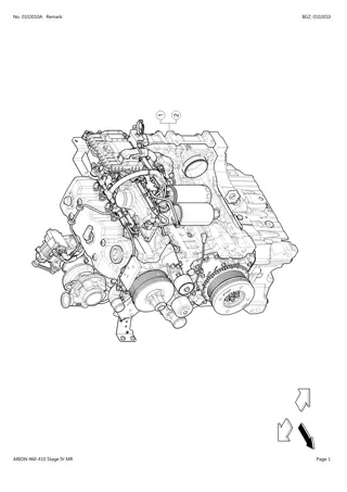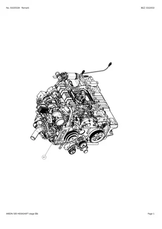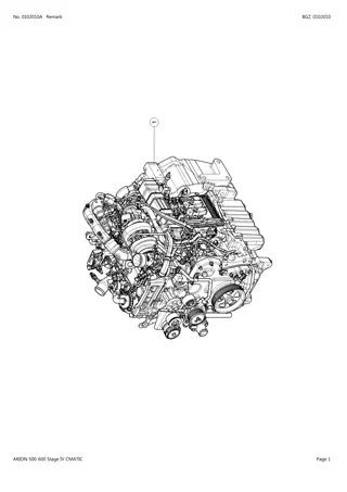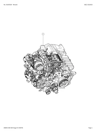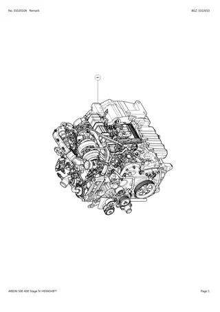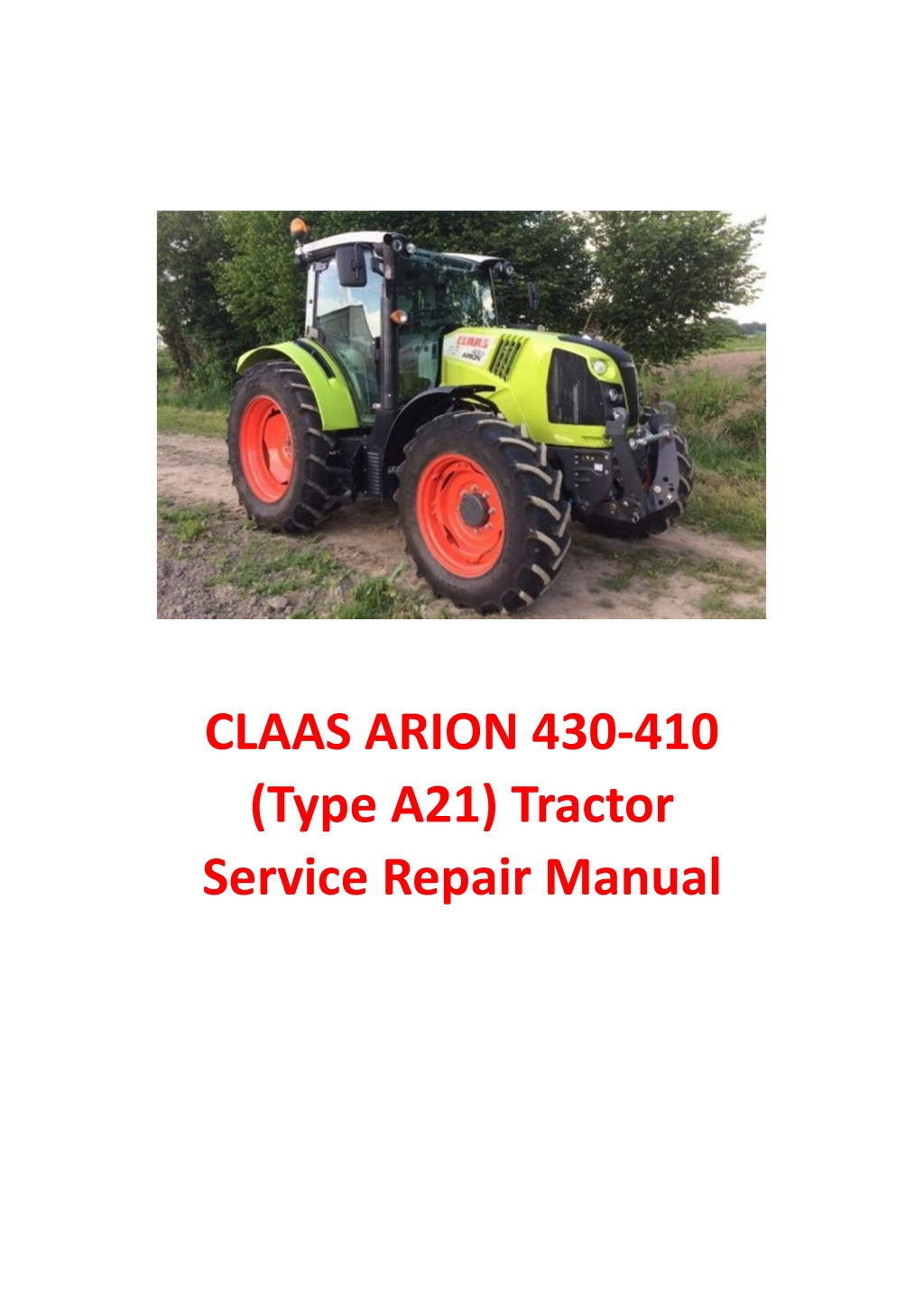
CLAAS ARION 430-410 (Type A21) Tractor Service Repair Manual Instant Download
Please open the website below to get the complete manualnn//
Download Presentation

Please find below an Image/Link to download the presentation.
The content on the website is provided AS IS for your information and personal use only. It may not be sold, licensed, or shared on other websites without obtaining consent from the author. Download presentation by click this link. If you encounter any issues during the download, it is possible that the publisher has removed the file from their server.
E N D
Presentation Transcript
CLAAS ARION 430-410 (Type A21) Tractor Service Repair Manual
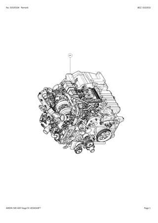
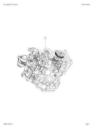
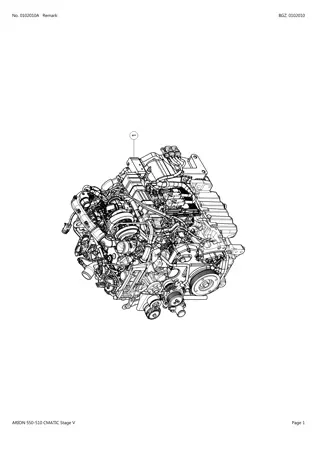
01 Engine 01 02 Complete assembly Operation n 1 Remove the cover by removing the screws (1). 1 Operation n 2 Drain the coolant. Drain the engine oil. If option: Drain the A/C unit. 101msm74 Fig. 1 Operation n 3 Disconnect the battery. 101msm75 Fig. 2 Operation n 4 If option: Remove the frame of the front loader. 101msm76 Fig. 3 13 Arion 430-410 01.2010 GB
01 Engine 01 02 Complete assembly Operation n 5 If option: Disconnect the (1) A/C lines. Operation n 6 Disconnect the engine harness (2). 1 2 101msm77 Fig. 4 Operation n 7 Disconnect the (1), (2) fuel supply and return lines. 1 101msm78 Fig. 5 2 101msm79 Fig. 6 14 Arion 430-410 01.2010 GB
https://www.ebooklibonline.com Hello dear friend! Thank you very much for reading. Enter the link into your browser. The full manual is available for immediate download. https://www.ebooklibonline.com
01 Engine 01 02 Complete assembly Operation n 8 Disconnect the transmission oil cooler lines (1). 1 101msm80 Fig. 7 Operation n 9 Disconnect the diesel fuel cooler lines (2). Operation n 10 Disconnect the steering lines (3). 1 2 101msm81 Fig. 8 3 3 101msm82 Fig. 9 101msm83 Fig. 10 15 Arion 430-410 01.2010 GB
01 Engine 01 02 Complete assembly Operation n 11 Disconnect the hoses from the cooling radiator (1) and (2). 1 101msm84 Fig. 11 2 101msm85 Fig. 12 Operation n 12 Disconnect the (1) air intake hose. 1 101msm86 Fig. 13 16 Arion 430-410 01.2010 GB
01 Engine 01 02 Complete assembly Operation n 13 Remove the hoses of the (1) air/air heat exchanger. 1 101msm87 Fig. 14 Operation n 14 Remove the exhaust extension. 101msm88 Fig. 15 Operation n 15 Disconnect the two heater hoses. 101msm89 Fig. 16 17 Arion 430-410 01.2010 GB
01 Engine 01 02 Complete assembly Operation n 16 Disconnect the air brake lines (1). 1 101msm90 Fig. 17 Operation n 17 Disconnect the starter wiring (1). 1 101msm91 Fig. 18 Operation n 18 If option: Disconnect the (1) front lifting lines. 1 101msm92 Fig. 19 18 Arion 430-410 01.2010 GB
01 Engine 01 02 Complete assembly Operation n 19 If option: Disconnect the front PTO harness (1). 1 101msm93 Fig. 20 Operation n 20 If option: Disconnect the (1) front PTO shaft. 1 101msm94 Fig. 21 Operation n 21 If option: Remove the front lift. 101msm95 Fig. 22 19 Arion 430-410 01.2010 GB
01 Engine 01 02 Complete assembly Operation n 22 Remove the housing and drive shaft. 101msm96 Fig. 23 Operation n 23 Remove the screw (1) from the cooling radiator bracket. 1 101msm97 Fig. 24 Operation n 24 Fit a prop under the engine and under the frame. Disconnect the front frame (1) from the engine by untiightening the screws (2). 2 1 101msm98 Fig. 25 20 Arion 430-410 01.2010 GB
01 Engine 01 02 Complete assembly Operation n 25 Sling the engine on 4 points to balance the load. Note: The engine has a weight of about 550 kg. Remove the screws from the (1) clutch casing. 1 101msm99 Fig. 26 Operation n 26 Important: Before removing the engine, check that all elements are disconnected properly. Removing the engine. Lay the engine on flat and clean ground. Remove all external engine elements (Starter, Alternator...). 101hsm05 Fig. 27 Refitting the complete engine Refit all external engine elements (Starter, Alternator...). Refit the engine elements and controls by performing the above operations in reverse sequence. Fill the A/C unit (see chapter 12 40). Fill the engine and the cooling circuit with oil (see operating manual). All tightening torques of the front chassis on the engine and the engine on the clutch casing are in part "03 00". 21 Arion 430-410 01.2010 GB
01 Engine 01 02 Complete assembly Blocking between the motor oil casing/front axle chassis A A E D C B 101msm64 Fig. 28 Assemble the front axle chassis onto the engine block. Tighten the 4 oiled nuts (A) at a torque of 21 daN.m. Measure the gap (B) on both sides between the motor oil casing (C) and the front axle chassis (D). Untighten the 4 nuts (A) and fit the number of shims matching the play (B)+ 0,10 mm. Tighten the 4 nuts (A) at a torque of 21 daN.m. Tighten the 2 lower screws (E) at a torque of 32 daN.m. 22 Arion 430-410 01.2010 GB
01 Engine 01 10 Engine sump Measuring liner flange depth inside the block Measure the liner flange depth inside the block and compare the two values with those specified If the values do not comply, thickness shims are available. Values indicated: Depth in the block.................................5,952 - 5,988 mm 121hsm39 Fig. 1 Measuring the liner flange Measure the thickness of the liner flange. If the values do not comply, thickness shims are available. Values indicated: Thickness..............................................6,022 - 6,058 mm 121hsm40 Fig. 2 Measuring parting surface flatness and center distance between the parting surface and the crankshaft bearing Values indicated: Maximum acceptable straightness error over the entire length or width ....................................................0,08 mm Maximum acceptable straightness error over the entire length of 150 mm..............................................0,025 mm Maximum ripple depth ...................................0,012 mm Center distance between the crankshaft bearing and the uppoer plate of the cylinder block............................... 337,896 - 337,972 mm 121hsm41 Fig. 3 24 Arion 430-410 01.2010 GB
01 Engine 01 10 Engine sump Removing the flywheel cover Remove the starter motor. Warning: The flywheel housing weighs about 20 kg. Apply handling precautions. Withdraw the screws attaching the flywheel housing to the cylinder block and those attaching the housing to the sump. Removing the flywheel casing. B Reassembling the engine flywheel casing A Inspect and clean the contact sufaces of the cylinder block and flywheel cover. Remove any sealing compound or material appled previously. 111msm15 Fig. 4 Note: Do not apply a sealing compound on the gasket or the contact surfaces of these covers. Fit a new camshaft O-ring (A) and on the gasket (B). Apply a continuous 2 to 4 mm layer of Loctite (518) on the flywheel cover. See illustration. Apply the seam at the center of the contact surfaces (except between screws 2 and 8) and fully circle the screws (except screw Nr.11). (518) 2 11 10 8 4 6 7 Important: Tighten the screws in the sequence and at the torque specified, within 10 minutes after assembling the parts. 5 3 1 9 Fit the flywheel housing onto the cylinder block, and tighten the screws at the values specified. Values indicated: Flywheel housing screw (1) to (8): 11 daN.m. Flywheel housing screw (9) and (12): 13 daN.m. Flywheel housing screw (10) and (11): 53 daN.m. Flywheel housing screw (13) and (14): 28 daN.m. 12 13 14 101msm0h Fig. 5 25 Arion 430-410 01.2010 GB
01 Engine 01 10 Engine sump Removing the front bearing gasket Fit puller n 60 0500 559 5. Using a drift punch, drill 32,5 mm holes at 120 using the tool base as guide. Screw 3 metal sheet screws (A). Tighten the pressure screw (B) and pull the gasket. Clean the crankshaft. B A 123hsm09 Fig. 6 Refitting the front bearing seal Important: To guarantee proper sealing, the external boundary of the crankshaft must be clean and dry. E C D Fit the pressure screw (C) of tool n 77 1113 251 7 in the crankshaft shank. Fit the adapter (D) onto the pressure screw and tighten the nut. Apply a thin layer of oil on the gasket lips and position the gasket on the adapter. Fit the fitting tool (E) onto the adapter and the guide sleeve (G). Tighten the nut (F) fully until the gasket is flush with the timing cover. 101msm22 Fig. 7 G F 123hsm10 Fig. 8 26 Arion 430-410 01.2010 GB
01 Engine 01 10 Engine sump Disassembly of the distributor casing Remove the engine oil casing. Remove the fan, the fan bracket. Remove the elbow (A) between the oil cooler and the water manifold. Remove the water pump pipes. Remove the crankshaft pulley. A 252hsm13 Fig. 9 Note: mark the position of the casing nuts and screws. Remove the nuts (D), screws (C), and screws (E) at the back of the front plate. Remove the timing casing. C E D D 252hsm14 Fig. 10 Refitting the timing cover Clean the parting surfaces. Fit a new gasket. Fit the timing cover and tighten the screws according to the sequence and torque specified (Refer to the part: "01 00"). Initial tightening: 2 daN.m. Final tightening: 3,5 daN.m. Fit the cap (A) of the high pressure pump gear with a new O-ring. Tighten to 5 daN.m. A 111hsm52 Fig. 11 27 Arion 430-410 01.2010 GB
01 Engine 01 10 Engine sump Removing the front plate Note: to be able to remove the front plate, first remove the timing gears. C Remove the 4 flush-head screws Torx (A) from the front plate. Remove the 6 threaded studs (B) and (C). Remove the front plate (D). A D B 111hsm16 Fig. 12 Remove the oil by-pass valve and the spring (E). Remove the pin of the upper intermediate shaft and lower gear intermediate shaft. E 111msm04 Fig. 13 28 Arion 430-410 01.2010 GB
Suggest: For more complete manuals. Please go to the home page. https://www.ebooklibonline.com If the above button click is invalid. Please download this document first, and then click the above link to download the complete manual. Thank you so much for reading
01 Engine 01 10 Engine sump Reassembly of the front plate Clean the parting surfaces. Fit the pin (A) in the front plate flush with the rear surface. Fit the intermediate shaft of the lower idler gear. A 111msm14 Fig. 14 Note: Fit the stop washer (F) while turning mark "x" away from the gear (towards the plate). Check the length and compression of the valve spring: Idle length: 51 mm. Tension of the spring compressed by 29 mm: 8,78 daN. Fit the oil bypass valve. Important: Ensure there is no oil, remnants of sealing compound or cleaning products on the cylinder block and the front plate. F 101msm0b Fig. 15 Apply a continuous seam (B) of Loctite (515) onto the cylinder block. Position the bead in the middle of the mating surfaces and all round the screw holes. Important: Tighten the screws at the torque specified within 10 minutes after assembling the parts. B 111hsm47 Fig. 16 29 Arion 430-410 01.2010 GB
01 Engine 01 10 Engine sump Install the front plate (D) and tighten the screws (E) at 2,5 daN.m and studs (B) and (C) at 3,5 daN.m. C E D B 111hsm48 Fig. 17 Removing the engine oil pan Warning: The oil pan weighs about 40 kg. Apply any precautions required. Note: Remove the oil pan when: - Changing the timing cover gasket. - Changing the flywheel cover gasket. - Accessing the crankshaft and piston rod. - Access to the oil pump. Remove the front axle linking shaft. Support the engine oil pan using a lifting tool. Loosen all the pan screws. Remove the shims between the pan and the front axle frame, while marking them to be able to refit the same number of shims on the same side. Remove the engine oil pan (A). A 111hsm53 Fig. 18 30 Arion 430-410 01.2010 GB
https://www.ebooklibonline.com Hello dear friend! Thank you very much for reading. Enter the link into your browser. The full manual is available for immediate download. https://www.ebooklibonline.com


