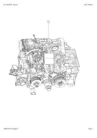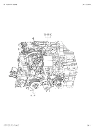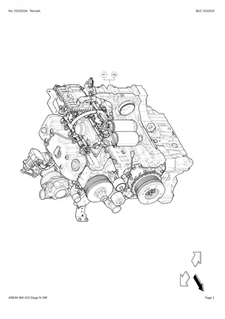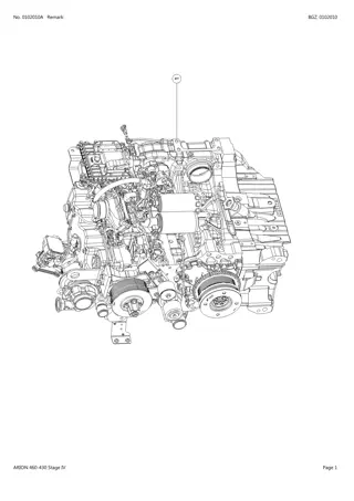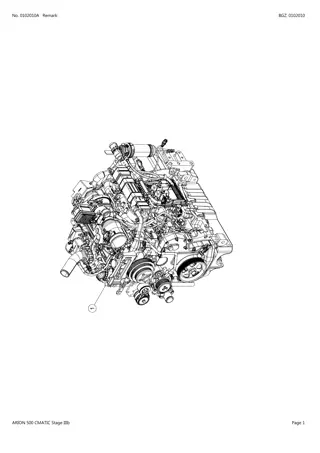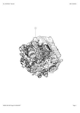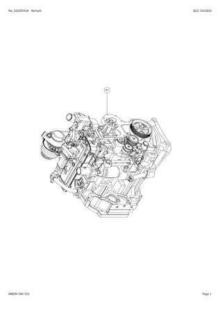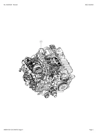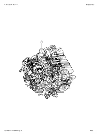
CLAAS ARION 540-510 (Type A18) Tractor Service Repair Manual Instant Download
Please open the website below to get the complete manualnn//
Download Presentation

Please find below an Image/Link to download the presentation.
The content on the website is provided AS IS for your information and personal use only. It may not be sold, licensed, or shared on other websites without obtaining consent from the author. Download presentation by click this link. If you encounter any issues during the download, it is possible that the publisher has removed the file from their server.
E N D
Presentation Transcript
A2 CYLINDER HEAD AND VALVES Arion 640-510 09.2008 GB
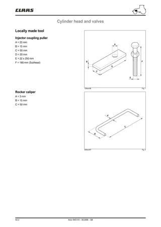
Cylinder head and valves Locally made tool Injector coupling puller A = 23 mm B = 15 mm C = 50 mm D = 20 mm E = 22 x 250 mm F = 180 mm (Subhead) A F B D C E 134hsm06 Fig. 1 Rocker caliper A = 3 mm B = 15 mm C = 50 mm A C B 324hsm97 Fig. 2 A2.2 Arion 640-510 09.2008 GB
Cylinder head and valves Inspecting valve bridges Clean the valve bridges and check they are not damaged. Measure the boreholes of the valve bridges (A) and check that the gap between one bore and another does not exceed the value specified. Maximum gap between bores...............................0,1 mm A 134hsm07 Fig. 3 Inspecting the rocker pin Note: Mark the location of the rockers when removing in order to facilitate refitting. Remove the caps (A) only to change them or to clean the rocker axis. Disassemble and search for traces of wear or damage. Change all parts which are damaged or non compliant with specifications. A 134hsm08 Fig. 4 Outer diameter of the axis ................19,962 - 20,038 mm Wear limit..........................................................19,91 mm 134hsm09 Fig. 5 A2.3 Arion 640-510 09.2008 GB
https://www.ebooklibonline.com Hello dear friend! Thank you very much for reading. Enter the link into your browser. The full manual is available for immediate download. https://www.ebooklibonline.com
Cylinder head and valves Inner diameter of the rocker..............20,065 - 20,115 mm Wear limit..........................................................20,16 mm 134hsm10 Fig. 6 Inspecting the rockers Remove and clean the rockers (A). Mark them for refitting. A 134hsm11 Fig. 7 Measure the outer diameter of the rockers. If it is below the value recommended, change it. Specified value: Rocker outer diameter..........................31,61 - 31,64 mm Measure rocker clearance in the bore. Specified value: Bore diameter (in the block).........................................31,70 - 31,75 mm Rocker and borehole clearance................0,06 - 0,13 mm Check the head on the rocker journals. If it is flat or concave, change the rocker and check the camshaft lobes. 134hsm12 Fig. 8 A2.4 Arion 640-510 09.2008 GB
Cylinder head and valves Measuring valve shrinkage Measurements must be made at a maximum distance of 3 mm from the edge of the valve head. Compare the measurements (A) between the 2 inlet and exhaust valves. Check that the gap does not exceed the value specified. A Note: If a cylinder has uneven valve wear, check the gap of boreholes on valve bridges. Specified value: Intake valve Shrinkage in the cylinder head .................0,77 - 1,27 mm Wear limit............................................................1,77 mm Exhaust valve Shrinkage in the cylinder head .................0,81 - 1,31 mm Wear limit............................................................1,81 mm Maximum gap for a pair of valves per cylinder........................ .........................................0,3 mm 131hsm33 Fig. 9 Cylinder head flatness Check cylinder head flatness using a precision rule and a set of shims. Check along the length, across and in diagonal in several locations. Specified value: Maximum acceptable straightness error over the entire length or width ....................................................0,08 mm Maximum acceptable straightness error over the entire length of 150 mm................................................0,03 mm Note: If the straightness error exceeds the values specified, rectify or change the cylinder head. 132hsm05 Fig. 10 A2.5 Arion 640-510 09.2008 GB
Cylinder head and valves Measuring cylinder head thickness Measure the cylinder head's thickness between the parting of the cylinder head cover riser and the combustion reaching. Specified value: New cylinder head............................104,87 - 105,13 mm Minimum acceptable cylinder head thickness 104,24 mm Maximum ripple depth ......................................0,012 mm Maximum material which can be removed when rectifying 0,76 mm Note: If the cylinder head thickness is below the minimum acceptable, do not rectify. Change the cylinder head. Important: Check cylinder head flatness using a precision rule and a set of shims. 132hsm06 Fig. 11 Valve guide measurement Measure wear on the valve guides. Specified value: Diameter of the valve guide borehole............................... 7,025 - 7,051 mm Clearance between rod and guide Intake.................................................0,012 - 0,064 mm Exhaust..............................................0,025 - 0,077 mm Wear limit between stem and guide....................0,15 mm 132hsm07 Fig. 12 A2.6 Arion 640-510 09.2008 GB
Cylinder head and valves Measuring the valve seat bore in the cylinder head If the dimensions of the boreholes do not comply with the values specified, machine the cylinder head according to the values. Specified value: Seat insert valve borehole Exhaust A. 36,436 - 36,462 mm. B. Reference 2,34 mm. C. 8,715 - 8,785 mm. D. 38 - 42 . E.Maximum radius 0,5 mm. Intake A. 37,436 - 37,462 mm. B. Reference 2,8 mm. C. 9,715 - 9,785 mm. D. 38 - 42 . E. Maximum radius 0,5 mm. Changing the outer diameter of seat insert valve boreholes. Exhaust..........................................36,487 - 36,513 mm Intake.............................................37,487 - 37,513 mm 132hsm08 Fig. 13 Measuring the valve springs Check spring tension using a spring compression device. Idle length.........................................................46,15 mm Specified value: Height comrpessed, spring tension............................. .46 mm from 18 to 27 N Spring compressed at 166 N............................37,21 mm Spring compressed at 356 N............................27,01 mm 131hsm34 Fig. 14 A2.7 Arion 640-510 09.2008 GB
Cylinder head and valves Measuring the valves Clean and inspect the valves, the valve stems, the tips of the stems and the retaining groove (A). Specified value: Valve head diameter Intake.................................................36,87 - 37,13 mm Exhaust..............................................35,87 - 36,13 mm A Note: The intake valves have a larger outer diameter and are recognized by a raised letter "O". 131hsm35 Fig. 15 0 131hsm36 Fig. 16 Valve stem diameter Intake.................................................6,987 - 7,013 mm Exhaust..............................................6,984 - 7,000 mm Maximum ovalization Inlet and exhaust ...........................................0,038 mm 131hsm37 Fig. 17 A2.8 Arion 640-510 09.2008 GB
Cylinder head and valves Check of the belt and the tensioner spring Loosen and remove the tensioner belt. Loosen the tensioner and plot a mark (A). Measure 21 mm from (A) and make a mark (B). Using a torque wrench, align the 2 marks. The spring's tension must be 1,8 to 2,2 daN m. Change the tensioner if required. A B 251msm04 Fig. 18 A2.9 Arion 640-510 11.2014 EN
Cylinder head and valves Removing the alternator and its bracket Disconnect the battery. Disconnect the alternator connections. Remove the alternator (A). Loosen the fastening screws on the bracket (B) and pull it. 1 A B 260hsm00 Fig. 21 Description 1 Pneumatic braking version (175 A alternator). A2.10 Arion 640-510 09.2008 GB
Cylinder head and valves 2 A B 260msm00 Fig. 22 Description 2 Pneumatic braking version (120 A alternator). 3 A B 260msm01 Fig. 23 Description 3 Version without air braking (120 and 175 ampere alternator). A2.11 Arion 640-510 09.2008 GB
Cylinder head and valves Refitting the alternator and bracket Refit the alternator bracket (B). Tighten the screws to a torque of 7 daN.m. Refit the alternator (A). Note: If the alternator pulley was removed, tighten the screw at a torque of 5 daN.m. Removing the viscouc coupling Remove the screws from the radiator nozzle (A). A Note: The viscous coupler thread on the hub is a left- hand thread. Using a pin wrench, hold the hub (B) and loosen the viscous coupler (C) and remove it. C Refitting the viscous coupling Note: The viscous coupler thread on the hub is a left- hand thread. B Refit the viscous coupler (C) on the hub (B). Using a pin wrench, tighten the viscous coupler at a torque of 9 daN.m. 253hsm00 Fig. 24 A2.12 Arion 640-510 09.2008 GB
Cylinder head and valves Removing the fan hub and bracket C B D A 251hsm29 Fig. 25 Loosen the drive belt using the tensioner (A) and remove it. Remove the hub of the viscous coupler (B). Remove the (C) pulley. Remove the pulley hub and its bracket (D). Refitting the fan hub and bracket Refit the fan bracket and hub (D). Tighten the screws to a torque of 7 daN.m. Refit the viscous coupler pulley (C) and hub (B). Tighten the screws to a torque of 7 daN.m. Position the belt. Tighten the belt using the tensioner (A). A2.13 Arion 640-510 09.2008 GB
Cylinder head and valves Removing the turbocharger Important: Let the exhaust circuit cool down before removing the turbocharger. A Note: Carefully clean the outside of the turbocharger and the surrounding area. Remove the air intake and exhaust ducts. Remove the coolant ducts (A). Disconnect electrical connections. Disconnect the oil inlet duct on the level of the oil filter head (B). Disconnect the oil return duct (C). Unscrew the 4 screws (D) of the exhaust manifold and remove the turbocharger. C D Refitting the turbocharger 142hsm04 Fig. 26 Important: Fill the oil return hole with clean motor oil and turn the turbocharger by hand. Position the turbocharger onto the exhaust manifold with a new gasket. Tighten the screws (D) to a torque of 7 daN.m. Connect the oil, air and coolant ducts. Connect the electric connections. B 142hsm00 Fig. 27 142hsm05 Fig. 28 A2.14 Arion 640-510 09.2008 GB
Cylinder head and valves Removing the turbocharger rod linkage Note: Proceed with caution when tightening or loosening the linkage screws as the screws are fragile. Remove the screw (A) from the actuator linkage. Remove the screw (B) from the turbocharger linkage. Remove the linkage. A 142hsm06 Fig. 29 Refitting the turbocharger linkage Note: Proceed with caution when tightening or loosening the linkage screws as the screws are fragile. Position the linkage on the flat of the turbocharger axis and the actuator. Tighten the screws (A) and (B) by hand. Use a wrench to hold the linkage. Tighten the screws (A), (B) to a torque of 0,7 daN.m. Check that the linkage moves freely. Otherwise readjust. B Important: Initialize the turbocharger module using M tadiag 2007. 142hsm07 Fig. 30 A B 142hsm08 Fig. 31 A2.15 Arion 640-510 09.2008 GB
Cylinder head and valves Removing the exhaust manifold Remove the turbocharger (the turbocharger can be removed with the exhaust manifold). Remove the oil return hose (C). Remove the exhaust manifold (A). Remove the exhaust connecting sleeves (B). Check the sleeves. A C 142hsm09 Fig. 32 B 142hsm10 Fig. 33 Refitting the exhaust manifold Refit the exhaust connecting sleeves. Use centering studs to refit the exhaust manifold. Tighten the screws (D) of the cylinders 3 and 4 initially at a torque of 7 daN.m. D 142hsm11 Fig. 34 A2.16 Arion 640-510 09.2008 GB
Cylinder head and valves Removing the cooler and ducts "EGR" A Remove the screws (A). Remove the exhaust duct "EGR" (B). Remove the cooling duct (C) by removing the screw (D) and collar (E). Remove the cooler "EGR". Remove screw (G). Remove the coolant ducts (F). B C Refitting the cooler and ducts "EGR" Refit the coolant duct (F). Replace the seals if required. Refit the cooler "EGR". Tighten the screw (G) to a torque of 3,5 daN.m. Refit the coolant duct (C). Refit the collar (E). Tighten the screw (D) to a torque of 3,5 daN.m. E 142hsm12 Fig. 35 D 142hsm13 Fig. 36 F G 142hsm14 Fig. 37 A2.17 Arion 640-510 09.2008 GB
Cylinder head and valves Removing the thermostat cover A Remove the screws (A). Remove the cover. Mark the position of the thermostats and remove them. Refitting the thermostat cover Change the gaskets of the thermostats (B). Position the thermostats at their original location. Refit the cover. Tighten the screws (A) to a torque of 4,7 daN.m. 254hsm03 Fig. 38 A B 254hsm02 Fig. 39 A2.18 Arion 640-510 09.2008 GB
Cylinder head and valves Removing the thermostat manifold Remove the screws from the coolant duct (A). Remove the screws (B) from the manifold and remove the manifold. B A Refitting the thermostat cover Note: Replace the seals. Refit the air intake manifold (C). Tighten the screws (B) to a torque of 7 daN.m. Position the coolant ducts (A) on the cylinder head. Tighten the screws (D) to a torque of 7 daN.m. 254hsm04 Fig. 40 A C D A B 254hsm05 Fig. 41 A2.19 Arion 640-510 09.2008 GB
Cylinder head and valves Removing the cylinder head cover Remove the caps (A) and the screws (B) from the cylinder head cover. A B C 133hsm01 Fig. 42 Remove the rocker cover (C). C 133hsm00 Fig. 43 A2.20 Arion 640-510 09.2008 GB
Suggest: For more complete manuals. Please go to the home page. https://www.ebooklibonline.com If the above button click is invalid. Please download this document first, and then click the above link to download the complete manual. Thank you so much for reading
Cylinder head and valves Refitting the cylinder head cover Important: change the sealing gasket (A) whenever removing the cylinder head cover. Fit the cylinder head cover (B). Fit the screws (C) and the O-rings (D). Tighten to 0,7 daN.m. Fit the caps (E). A 133hsm02 Fig. 44 E C D B 133hsm03 Fig. 45 A2.21 Arion 640-510 09.2008 GB
Cylinder head and valves Removing the rocker arm assembly B A D Install the 6 locally made U-bolts (A) to hold the rockers. See page 2 Locally made tool. Untighten the screws (B) and (C). Loosen the screws on the flanges (D). Remove the bearings *1. Removing the valve rocker shaft assembly and push rods (E). Mark the location of the rockers when removing in order to facilitate refitting. Remove the bridges (F). 134hsm13 Fig. 46 A C 134hsm14 Fig. 47 E F 134hsm15 Fig. 48 A2.22 Arion 640-510 09.2008 GB
https://www.ebooklibonline.com Hello dear friend! Thank you very much for reading. Enter the link into your browser. The full manual is available for immediate download. https://www.ebooklibonline.com

