ChirpRfFreqSlope Changes Overview
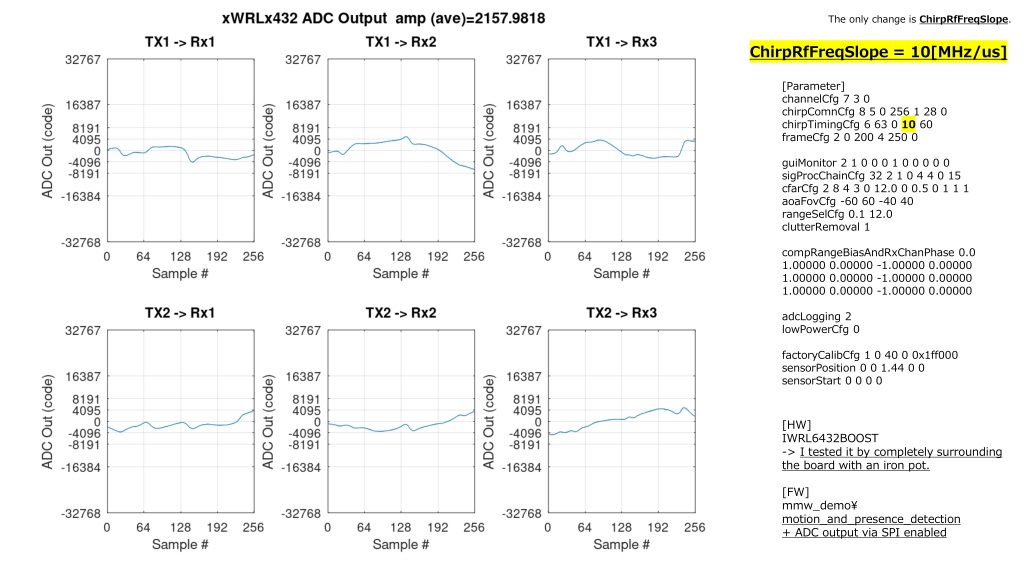

[Parameter]
channelCfg 7 3 0
chirpComnCfg 8 5 0 256 1 28 0
chirpTimingCfg 6 63 0
10
60
frameCfg 2 0 200 4 250 0
guiMonitor 2 1 0 0 0 1 0 0 0 0 0
sigProcChainCfg 32 2 1 0 4 4 0 15
cfarCfg 2 8 4 3 0 12.0 0 0.5 0 1 1 1
aoaFovCfg -60 60 -40 40
rangeSelCfg 0.1 12.0
clutterRemoval 1
compRangeBiasAndRxChanPhase 0.0
1.00000 0.00000 -1.00000 0.00000
1.00000 0.00000 -1.00000 0.00000
1.00000 0.00000 -1.00000 0.00000
adcLogging 2
lowPowerCfg 0
factoryCalibCfg 1 0 40 0 0x1ff000
sensorPosition 0 0 1.44 0 0
sensorStart 0 0 0 0
[HW]
IWRL6432BOOST
->
I tested it by completely surrounding
the board with an iron pot.
[FW]
mmw_demo\
motion_and_presence_detection
+ ADC output via SPI
enabled
ChirpRfFreqSlope
=
10[MHz/us]
The only change is
ChirpRfFreqSlope
.

[Parameter]
channelCfg 7 3 0
chirpComnCfg 8 5 0 256 1 28 0
chirpTimingCfg 6 63 0
35
60
frameCfg 2 0 200 4 250 0
guiMonitor 2 1 0 0 0 1 0 0 0 0 0
sigProcChainCfg 32 2 1 0 4 4 0 15
cfarCfg 2 8 4 3 0 12.0 0 0.5 0 1 1 1
aoaFovCfg -60 60 -40 40
rangeSelCfg 0.1 12.0
clutterRemoval 1
compRangeBiasAndRxChanPhase 0.0
1.00000 0.00000 -1.00000 0.00000
1.00000 0.00000 -1.00000 0.00000
1.00000 0.00000 -1.00000 0.00000
adcLogging 2
lowPowerCfg 0
factoryCalibCfg 1 0 40 0 0x1ff000
sensorPosition 0 0 1.44 0 0
sensorStart 0 0 0 0
[HW]
IWRL6432BOOST
->
I tested it by completely surrounding
the board with an iron pot.
[FW]
mmw_demo\
motion_and_presence_detection
+ ADC output via SPI
enabled
ChirpRfFreqSlope
=
35[MHz/us]
The only change is
ChirpRfFreqSlope
.
[Parameter]
channelCfg 7 3 0
chirpComnCfg 8 5 0 256 1 28 0
chirpTimingCfg 6 63 0
75
60
frameCfg 2 0 200 4 250 0
guiMonitor 2 1 0 0 0 1 0 0 0 0 0
sigProcChainCfg 32 2 1 0 4 4 0 15
cfarCfg 2 8 4 3 0 12.0 0 0.5 0 1 1 1
aoaFovCfg -60 60 -40 40
rangeSelCfg 0.1 12.0
clutterRemoval 1
compRangeBiasAndRxChanPhase 0.0
1.00000 0.00000 -1.00000 0.00000
1.00000 0.00000 -1.00000 0.00000
1.00000 0.00000 -1.00000 0.00000
adcLogging 2
lowPowerCfg 0
factoryCalibCfg 1 0 40 0 0x1ff000
sensorPosition 0 0 1.44 0 0
sensorStart 0 0 0 0
[HW]
IWRL6432BOOST
->
I tested it by completely surrounding
the board with an iron pot.
[FW]
mmw_demo\
motion_and_presence_detection
+ ADC output via SPI
enabled
ChirpRfFreqSlope
=
75[MHz/us]
The only change is
ChirpRfFreqSlope
.
[Parameter]
channelCfg 7 3 0
chirpComnCfg 8 5 0 256 1 28 0
chirpTimingCfg 6 63 0
1
4
0
60
frameCfg 2 0 200 4 250 0
guiMonitor 2 1 0 0 0 1 0 0 0 0 0
sigProcChainCfg 32 2 1 0 4 4 0 15
cfarCfg 2 8 4 3 0 12.0 0 0.5 0 1 1 1
aoaFovCfg -60 60 -40 40
rangeSelCfg 0.1 12.0
clutterRemoval 1
compRangeBiasAndRxChanPhase 0.0
1.00000 0.00000 -1.00000 0.00000
1.00000 0.00000 -1.00000 0.00000
1.00000 0.00000 -1.00000 0.00000
adcLogging 2
lowPowerCfg 0
factoryCalibCfg 1 0 40 0 0x1ff000
sensorPosition 0 0 1.44 0 0
sensorStart 0 0 0 0
[HW]
IWRL6432BOOST
->
I tested it by completely surrounding
the board with an iron pot.
[FW]
mmw_demo\
motion_and_presence_detection
+ ADC output via SPI
enabled
ChirpRfFreqSlope
=
140[MHz/us]
The only change is
ChirpRfFreqSlope
.
[Parameter]
channelCfg 7 3 0
chirpComnCfg 8 5 0 256 1 28 0
chirpTimingCfg 6 63 0
10
60
frameCfg 2 0 200 4 250 0
guiMonitor 2 1 0 0 0 1 0 0 0 0 0
sigProcChainCfg 32 2 1 0 4 4 0 15
cfarCfg 2 8 4 3 0 12.0 0 0.5 0 1 1 1
aoaFovCfg -60 60 -40 40
rangeSelCfg 0.1 12.0
clutterRemoval 1
compRangeBiasAndRxChanPhase 0.0
1.00000 0.00000 -1.00000 0.00000
1.00000 0.00000 -1.00000 0.00000
1.00000 0.00000 -1.00000 0.00000
adcLogging 2
lowPowerCfg 0
factoryCalibCfg 1 0 40 0 0x1ff000
sensorPosition 0 0 1.44 0 0
sensorStart 0 0 0 0
[HW]
IWRL6432BOOST
->
I tested it by completely surrounding
the board with an iron pot.
[FW]
mmw_demo\
motion_and_presence_detection
+ ADC output via SPI
enabled
ChirpRfFreqSlope
=
10[MHz/us]
The only change is
ChirpRfFreqSlope
.
[Parameter]
channelCfg 7 3 0
chirpComnCfg 8 5 0 256 1 28 0
chirpTimingCfg 6 63 0
35
60
frameCfg 2 0 200 4 250 0
guiMonitor 2 1 0 0 0 1 0 0 0 0 0
sigProcChainCfg 32 2 1 0 4 4 0 15
cfarCfg 2 8 4 3 0 12.0 0 0.5 0 1 1 1
aoaFovCfg -60 60 -40 40
rangeSelCfg 0.1 12.0
clutterRemoval 1
compRangeBiasAndRxChanPhase 0.0
1.00000 0.00000 -1.00000 0.00000
1.00000 0.00000 -1.00000 0.00000
1.00000 0.00000 -1.00000 0.00000
adcLogging 2
lowPowerCfg 0
factoryCalibCfg 1 0 40 0 0x1ff000
sensorPosition 0 0 1.44 0 0
sensorStart 0 0 0 0
[HW]
IWRL6432BOOST
->
I tested it by completely surrounding
the board with an iron pot.
[FW]
mmw_demo\
motion_and_presence_detection
+ ADC output via SPI
enabled
ChirpRfFreqSlope
=
35[MHz/us]
The only change is
ChirpRfFreqSlope
.
[Parameter]
channelCfg 7 3 0
chirpComnCfg 8 5 0 256 1 28 0
chirpTimingCfg 6 63 0
75
60
frameCfg 2 0 200 4 250 0
guiMonitor 2 1 0 0 0 1 0 0 0 0 0
sigProcChainCfg 32 2 1 0 4 4 0 15
cfarCfg 2 8 4 3 0 12.0 0 0.5 0 1 1 1
aoaFovCfg -60 60 -40 40
rangeSelCfg 0.1 12.0
clutterRemoval 1
compRangeBiasAndRxChanPhase 0.0
1.00000 0.00000 -1.00000 0.00000
1.00000 0.00000 -1.00000 0.00000
1.00000 0.00000 -1.00000 0.00000
adcLogging 2
lowPowerCfg 0
factoryCalibCfg 1 0 40 0 0x1ff000
sensorPosition 0 0 1.44 0 0
sensorStart 0 0 0 0
[HW]
IWRL6432BOOST
->
I tested it by completely surrounding
the board with an iron pot.
[FW]
mmw_demo\
motion_and_presence_detection
+ ADC output via SPI
enabled
ChirpRfFreqSlope
=
75[MHz/us]
The only change is
ChirpRfFreqSlope
.
[Parameter]
channelCfg 7 3 0
chirpComnCfg 8 5 0 256 1 28 0
chirpTimingCfg 6 63 0
1
4
0
60
frameCfg 2 0 200 4 250 0
guiMonitor 2 1 0 0 0 1 0 0 0 0 0
sigProcChainCfg 32 2 1 0 4 4 0 15
cfarCfg 2 8 4 3 0 12.0 0 0.5 0 1 1 1
aoaFovCfg -60 60 -40 40
rangeSelCfg 0.1 12.0
clutterRemoval 1
compRangeBiasAndRxChanPhase 0.0
1.00000 0.00000 -1.00000 0.00000
1.00000 0.00000 -1.00000 0.00000
1.00000 0.00000 -1.00000 0.00000
adcLogging 2
lowPowerCfg 0
factoryCalibCfg 1 0 40 0 0x1ff000
sensorPosition 0 0 1.44 0 0
sensorStart 0 0 0 0
[HW]
IWRL6432BOOST
->
I tested it by completely surrounding
the board with an iron pot.
[FW]
mmw_demo\
motion_and_presence_detection
+ ADC output via SPI
enabled
ChirpRfFreqSlope
=
140[MHz/us]
The only change is
ChirpRfFreqSlope
.
In this content, different settings of ChirpRfFreqSlope parameter are explored with values of 10, 35, 75, and 140 MHz/us. The parameter variations are analyzed within a radar system configuration involving channel settings, chirp timing, frame configuration, signal processing chain, and more. The impact of altering ChirpRfFreqSlope on system performance and characteristics is examined through practical testing and description of results.

Uploaded on Feb 17, 2025 | 0 Views
Download Presentation

Please find below an Image/Link to download the presentation.
The content on the website is provided AS IS for your information and personal use only. It may not be sold, licensed, or shared on other websites without obtaining consent from the author.If you encounter any issues during the download, it is possible that the publisher has removed the file from their server.
You are allowed to download the files provided on this website for personal or commercial use, subject to the condition that they are used lawfully. All files are the property of their respective owners.
The content on the website is provided AS IS for your information and personal use only. It may not be sold, licensed, or shared on other websites without obtaining consent from the author.
E N D
Presentation Transcript
The only change is ChirpRfFreqSlope. ChirpRfFreqSlope = 10[MHz/us] [Parameter] channelCfg 7 3 0 chirpComnCfg 8 5 0 256 1 28 0 chirpTimingCfg 6 63 0 10 60 frameCfg 2 0 200 4 250 0 guiMonitor 2 1 0 0 0 1 0 0 0 0 0 sigProcChainCfg 32 2 1 0 4 4 0 15 cfarCfg 2 8 4 3 0 12.0 0 0.5 0 1 1 1 aoaFovCfg -60 60 -40 40 rangeSelCfg 0.1 12.0 clutterRemoval 1 compRangeBiasAndRxChanPhase 0.0 1.00000 0.00000 -1.00000 0.00000 1.00000 0.00000 -1.00000 0.00000 1.00000 0.00000 -1.00000 0.00000 adcLogging 2 lowPowerCfg 0 factoryCalibCfg 1 0 40 0 0x1ff000 sensorPosition 0 0 1.44 0 0 sensorStart 0 0 0 0 [HW] IWRL6432BOOST -> I tested it by completely surrounding the board with an iron pot. [FW] mmw_demo\ motion_and_presence_detection + ADC output via SPI enabled
The only change is ChirpRfFreqSlope. ChirpRfFreqSlope = 35[MHz/us] [Parameter] channelCfg 7 3 0 chirpComnCfg 8 5 0 256 1 28 0 chirpTimingCfg 6 63 0 35 60 frameCfg 2 0 200 4 250 0 guiMonitor 2 1 0 0 0 1 0 0 0 0 0 sigProcChainCfg 32 2 1 0 4 4 0 15 cfarCfg 2 8 4 3 0 12.0 0 0.5 0 1 1 1 aoaFovCfg -60 60 -40 40 rangeSelCfg 0.1 12.0 clutterRemoval 1 compRangeBiasAndRxChanPhase 0.0 1.00000 0.00000 -1.00000 0.00000 1.00000 0.00000 -1.00000 0.00000 1.00000 0.00000 -1.00000 0.00000 adcLogging 2 lowPowerCfg 0 factoryCalibCfg 1 0 40 0 0x1ff000 sensorPosition 0 0 1.44 0 0 sensorStart 0 0 0 0 [HW] IWRL6432BOOST -> I tested it by completely surrounding the board with an iron pot. [FW] mmw_demo\ motion_and_presence_detection + ADC output via SPI enabled
The only change is ChirpRfFreqSlope. ChirpRfFreqSlope = 75[MHz/us] [Parameter] channelCfg 7 3 0 chirpComnCfg 8 5 0 256 1 28 0 chirpTimingCfg 6 63 0 75 60 frameCfg 2 0 200 4 250 0 guiMonitor 2 1 0 0 0 1 0 0 0 0 0 sigProcChainCfg 32 2 1 0 4 4 0 15 cfarCfg 2 8 4 3 0 12.0 0 0.5 0 1 1 1 aoaFovCfg -60 60 -40 40 rangeSelCfg 0.1 12.0 clutterRemoval 1 compRangeBiasAndRxChanPhase 0.0 1.00000 0.00000 -1.00000 0.00000 1.00000 0.00000 -1.00000 0.00000 1.00000 0.00000 -1.00000 0.00000 adcLogging 2 lowPowerCfg 0 factoryCalibCfg 1 0 40 0 0x1ff000 sensorPosition 0 0 1.44 0 0 sensorStart 0 0 0 0 [HW] IWRL6432BOOST -> I tested it by completely surrounding the board with an iron pot. [FW] mmw_demo\ motion_and_presence_detection + ADC output via SPI enabled
The only change is ChirpRfFreqSlope. ChirpRfFreqSlope = 140[MHz/us] [Parameter] channelCfg 7 3 0 chirpComnCfg 8 5 0 256 1 28 0 chirpTimingCfg 6 63 0 140 60 frameCfg 2 0 200 4 250 0 guiMonitor 2 1 0 0 0 1 0 0 0 0 0 sigProcChainCfg 32 2 1 0 4 4 0 15 cfarCfg 2 8 4 3 0 12.0 0 0.5 0 1 1 1 aoaFovCfg -60 60 -40 40 rangeSelCfg 0.1 12.0 clutterRemoval 1 compRangeBiasAndRxChanPhase 0.0 1.00000 0.00000 -1.00000 0.00000 1.00000 0.00000 -1.00000 0.00000 1.00000 0.00000 -1.00000 0.00000 adcLogging 2 lowPowerCfg 0 factoryCalibCfg 1 0 40 0 0x1ff000 sensorPosition 0 0 1.44 0 0 sensorStart 0 0 0 0 [HW] IWRL6432BOOST -> I tested it by completely surrounding the board with an iron pot. [FW] mmw_demo\ motion_and_presence_detection + ADC output via SPI enabled