Changes in Airfield Markings and Advisory Circulars for Airport Engineering
The changes in airfield markings and advisory circulars for airport engineering, as outlined in AC 150/5340-1M and AC 150/5370-10H, include improvements to guidance, industry standards, and marking performance. Quality control measures have been implemented to enhance the effectiveness and longevity of airfield markings. Consulting engineers and their RPRs play a key role in ensuring clients inherit markings that are impactful and durable. Proper maintenance practices, alignment with specifications, and adherence to dimensions are essential for achieving desired marking effects.
Download Presentation

Please find below an Image/Link to download the presentation.
The content on the website is provided AS IS for your information and personal use only. It may not be sold, licensed, or shared on other websites without obtaining consent from the author.If you encounter any issues during the download, it is possible that the publisher has removed the file from their server.
You are allowed to download the files provided on this website for personal or commercial use, subject to the condition that they are used lawfully. All files are the property of their respective owners.
The content on the website is provided AS IS for your information and personal use only. It may not be sold, licensed, or shared on other websites without obtaining consent from the author.
E N D
Presentation Transcript
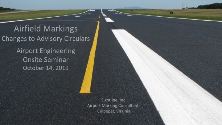
Airfield Markings Changes to Advisory Circulars Airport Engineering Onsite Seminar October 14, 2019 Sightline, Inc. Airport Marking Consultants Culpeper, Virginia
Overview How has the What, Where, and When of airfield markings changed in AC 150/5340-1M? What are the quality control measures that have been added to AC 150/5370-10H, Item P-620 Airfield and Taxiway Markings What aspects of the P-620 could be applied to the maintenance of airfield markings? What responsibilities do consulting engineers and their RPRs have to ensure their clients inherit markings that are effective and will last? If markings are the icing on the cake , how can engineers make sure they will have the desired effect? 2
Changes to ACs AC 150/5340-1M 5/10/19 AC 150/5370-10H 12/21/18 (Item P-620 Runway and Taxiway Markings) Reasons for the changes: Clarify guidance Improve industry standards Improve marking performance Quality Control measures
AC 150/5340-1M May 10, 2019 Centering of Runway Landing Designation Markings (Para. 2.3.5)
Footnotes on Numbers All characters are 60-feet high and 20-feet wide unless otherwise specified. Vertical stroke is 5 feet wide; horizontal stroke 10 ft. All designations are spaced 15 feet apart, with exception to the number 11 (27 ). Single designations are centered on the runway pavement centerline. For double designations, the center of the outer edges of the two numerals is centered on the runway pavement centerline. 5
6 [1.8] 7 [2.1] HORIZONTAL STROKE 3 [0.09] 10 [3] 19 [5.7] 22 [6.6] 13 [3.9] 18 [5.4] 10 [3] DIAGONAL STROKE 8 [2.4] 7 [2.1] 19 [5.7] 7 [2.1] 15 [4.5] 2 [0.06] 5 [1.5] 9 [2.7] VERTICAL STROKE 5 [1.5] 13[3.9] 11 [3.3] 23 [6.9] 10 [3] 26 [7.8] 19 [5.7] 13 [3.9] 17 [5.1] 45 13 [3.9] 63 [18.9] 63 [18.9] 2 [0.6] 13 [3.9] 7 [2.1] SEE NOTE 2 17 [5.1] 5 [1.5] 14 [2.4] 15 [4.5] 27 [8.1] 10 [3] 25 [7.5] SEE NOTE 2 5 [1.5] 6 2 [0.06] 14 [2.4] SEE NOTES 2 AND 5 NOTES : 1. DIMENSIONS ARE EXPRESSED: FEET [METERS]. 5. THE NUMERAL "1", WHEN USED ALONE, CONTAINS A HORIZONTAL STROKE AS SHOWN TO DIFFERENTIATE IT FROM THE RUNWAY CENTERLINE MARKING. 2. ALL CHARACTERS SHALL HAVE THESE CHARACTERISTICS (UNLESS OTHERWISE SPECIFIED): 60 [18] HIGH 20 [6] WIDE VERTICAL STROKE OF 5 [1.5] HORIZONTAL STROKE OF 10 [30] DIAGONAL STROKE OF 5 [1.5] 6. SINGLE DESIGNATIONS ARE CENTERED ON THE RUNWAY PAVEMENT CENTERLINE. FOR DOUBLE DESIGNATIONS, THE CENTER OF THE OUTER EDGES OF THE TWO NUMERALS IS IS CENTERED ON THE RUNWAY PAVEMENT CENTERLINE. 7. WHERE THE RUNWAY DESIGNATION CONSISTS OF A NUMBER AND A LETTER, THE NUMBER AND LETTER ARE LOCATED ON THE RUNWAY CENTERLINE IN A STACKED ARRANGEMENT AS SHOWN 3. ALL NUMERALS EXCEPT THE NUMBER ELEVEN AS SHOWN ARE HORIZONTALLY SPACED 15 [4.5] APART. IN FIGURE 1. 4. SINGLE DIGITS MUST NOT BE PRECEDED BY A ZERO.
6 [1.8] 7 [2.1] HORIZONTAL STROKE 3 [0.09] 10 [3] 19 [5.7] 22 [6.6] 13 [3.9] 18 [5.4] 10 [3] DIAGONAL STROKE 8 [2.4] 7 [2.1] 19 [5.7] 7 [2.1] 15 [4.5] 2 [0.06] 5 [1.5] 9 [2.7] VERTICAL STROKE 5 [1.5] 13[3.9] 11 [3.3] 6 [1.8] 7 [2.1] HORIZONTAL STROKE 3 [0.09] 10 [3] 23 [6.9] 19 [5.7] 10 [3] 22 [6.6] 26 [7.8] 19 [5.7] 13 [3.9] 17 [5.1] 45 13 [3.9] 13 [3.9] 18 [5.4] 10 [3] 63 [18.9] 63 [18.9] DIAGONAL STROKE 13 [3.9] 2 [0.6] 8 [2.4] 7 [2.1] 19 [5.7] 7 [2.1] 7 [2.1] 15 [4.5] SEE NOTE 2 17 [5.1] 2 [0.06] 5 [1.5] 9 [2.7] 5 [1.5] VERTICAL STROKE 14 [2.4] 7 15 [4.5] 5 [1.5] 27 [8.1] 13[3.9] 11 [3.3] 23 [6.9] 10 [3] 10 [3] 26 [7.8] 19 [5.7] 13 [3.9] 17 [5.1] 45 13 [3.9] 25 [7.5] 63 [18.9] 63 [18.9] 2 [0.6] 13 [3.9] 7 [2.1] SEE NOTE 2 5 [1.5] 2 [0.06] 14 [2.4] SEE NOTES 2 AND 5 SEE NOTE 2 17 [5.1] NOTES : 5 [1.5] THE NUMERAL "1", WHEN USED ALONE, CONTAINS A HORIZONTAL STROKE AS SHOWN TO DIFFERENTIATE IT FROM THE RUNWAY CENTERLINE MARKING. 1. DIMENSIONS ARE EXPRESSED: FEET [METERS]. 5. 14 [2.4] 2. ALL CHARACTERS SHALL HAVE THESE CHARACTERISTICS 15 [4.5] (UNLESS OTHERWISE SPECIFIED): 60 [18] HIGH 20 [6] WIDE VERTICAL STROKE OF 5 [1.5] HORIZONTAL STROKE OF 10 [30] DIAGONAL STROKE OF 5 [1.5] 27 [8.1] 6. SINGLE DESIGNATIONS ARE CENTERED ON THE RUNWAY PAVEMENT CENTERLINE. FOR DOUBLE DESIGNATIONS, THE CENTER OF THE OUTER EDGES OF THE TWO NUMERALS IS IS CENTERED ON THE RUNWAY PAVEMENT CENTERLINE. 7. WHERE THE RUNWAY DESIGNATION CONSISTS OF A NUMBER AND A LETTER, THE NUMBER AND LETTER ARE LOCATED ON THE RUNWAY CENTERLINE IN A STACKED ARRANGEMENT AS SHOWN 3. ALL NUMERALS EXCEPT THE NUMBER ELEVEN AS SHOWN ARE HORIZONTALLY SPACED 15 [4.5] APART. 10 [3] IN FIGURE 1. 4. SINGLE DIGITS MUST NOT BE PRECEDED BY A ZERO. 25 [7.5] SEE NOTE 2 5 [1.5] 2 [0.06] 14 [2.4] SEE NOTES 2 AND 5 NOTES : 1. DIMENSIONS ARE EXPRESSED: FEET [METERS]. 5. THE NUMERAL "1", WHEN USED ALONE, CONTAINS A HORIZONTAL STROKE AS SHOWN TO DIFFERENTIATE IT FROM THE RUNWAY CENTERLINE MARKING. 2. ALL CHARACTERS SHALL HAVE THESE CHARACTERISTICS (UNLESS OTHERWISE SPECIFIED): 60 [18] HIGH 20 [6] WIDE VERTICAL STROKE OF 5 [1.5] HORIZONTAL STROKE OF 10 [30] DIAGONAL STROKE OF 5 [1.5] 6. SINGLE DESIGNATIONS ARE CENTERED ON THE RUNWAY PAVEMENT CENTERLINE. FOR DOUBLE DESIGNATIONS, THE CENTER OF THE OUTER EDGES OF THE TWO NUMERALS IS IS CENTERED ON THE RUNWAY PAVEMENT CENTERLINE. 7. WHERE THE RUNWAY DESIGNATION CONSISTS OF A NUMBER AND A LETTER, THE NUMBER AND LETTER ARE LOCATED ON THE RUNWAY CENTERLINE IN A STACKED ARRANGEMENT AS SHOWN 3. ALL NUMERALS EXCEPT THE NUMBER ELEVEN AS SHOWN ARE HORIZONTALLY SPACED 15 [4.5] APART. IN FIGURE 1. 4. SINGLE DIGITS MUST NOT BE PRECEDED BY A ZERO.
Center Runway Landing Designator Markings. 48 ft 64 ft
Center Runway Landing Designator Markings. 54 ft. 54 ft. 10
AC 150/5340-1M May 10, 2019 No taxi islands new definition (Para 1.2.4)
Island. An unused paved or grassy area along a taxiway, between taxiways, between runways, or between a taxiway and a runway. Paved islands are clearly marked as unusable, either by painting or the use of artificial turf. For the purposes of this AC, certain islands are referred to as No- taxi islands. 12
Case 1 To avoid taxiway excursions onto unpaved areas or paved areas not intended for use by providing pilots with visual cues to discern the edge of usable full-strength pavement. 13
Case 2 To prevent runway incursions when terminal aprons are in close proximity to the runway by creating turning maneuvers with the use of no-taxi islands and reconfigured taxi routes. 14
Case 3 To avoid runway incursions or wrong runway take-offs due to oversized entrance taxiway. 15
Case 3 16
Case 3 17
Case 4 Intended to reduce incursions due to multi-entrance taxiways located on a single, expansive, paved area. BEFORE
Case 4 19
Case 4 Obtain standard width taxiways by inserting green no-taxi islands and creating individual taxiway entrances. 20
AC 150/5340-1M May 10, 2019 Recommends training of personnel who apply [or monitor] surface markings.
PILOT CERTIFICATE TRAINING AT DULLES INTERNATIONAL AIRPORT 22
4. Paragraph 1.3.8. The advisory circular makes the recommendation for training of personnel that perform [monitor] the application of surface markings, prepare surfaces to receive surface markings, remove markings, etc., as important aspects to obtaining desired markings and longevity. 23
AC 150/5340-1M (continued) Any stencils used must not leave stencil gaps (Para. 1.3.9)
In all cases, inscriptions follow Appendix B inscription criteria. 26
AC 150/5340-1M (continued) Added notes to Table 1-1 and Table 1-2 to clarify the use of black borders (Para. 1.4)
Table 1-2. Requirements and recommendations for black borders and glass beads (by 2015) per AC 150/5340-1M Marking Description Black Border (6-in min) Glass Beads Runway centerline marking Required Required Runway threshold marking Required Required Runway displaced threshold marking Required Required Runway threshold bar marking Required Required Runway aiming point markings Required Required Runway landing designator marking Required Required Runway touchdown zone markings Required Required Runway edge marking Recommended Recommended Runway demarcation bar marking Recommended Recommended All holding position markings Required Required Taxiway centerline markings Recommended Required All taxiway centerline markings on SMGCS routes Required Required Enhanced taxiway centerline markings Required Required Taxiway edge markings Recommended Recommended Geographic position markings Required Required Surface painted signs Required Required Non-movement area boundary markings Required Required
Table 1-1. General Guidelines for Painting a Black Border Age of Pavement Surface Up to 2 years old Over 2 years old Pavement Surface Type New Portland Cement Concrete Yes Yes Yes Asphaltic Concrete No No Yes Asphalt Treated (Sealcoat) No No Yes
Note 1: Table 1-1 and Table 1-2 are interrelated. Surface markings per Table 1-2 that require black borders may initially be deferred for the case of new, dark-colored asphalt concrete; new asphalt treated pavement surfaces for up to two years as per Table 1-1. . . . New light-colored asphalt projects require the black borders upon completion. Note 2: Surface markings identified per Note 1 that sufficiently fade before 2 years shall receive black borders. 32
Black borders provide contrast to markings on light colored pavement for conspicuity during daylight hours. Glass beads provide conspicuity to markings during darkness. Both are necessary to improve situational awareness.
AC 150/5340-1M (continued) Use of the Pattern B (ILS/MLS) Holding Position Marking for Precision Obstacle Free Zone (POFZ) or Runway Approach/ Departure areas of a runway.
New use of Pattern B (Ladder) Holding Position Marking at Departure/Approach ends. Comply by July 2020
AC 150/5340-1M (continued) Modified enhanced taxiway centerline that are collinear with an on-center surface painted holding position sign.
AC 150/5340-1M 2 to 3 ft 3 ft
AC 150/5340-1M (continued) When a black border is not painted on a holding position marking, the taxiway edge marking stops 6-inches away from the hold bar.
3 ft. 3 ft. 3 ft. 6 to 12 in. 12 in. 12 in. 12 in. 6 to 12 in. 9 ft. 6 to 12 in. 6 in. 6 in. 6 in. 6 in. 3 ft. 3 to 6 in.
AC 150/5370-10H, Item P-620 Tailored Surface Preparation Specifications Good Inspection Quality Materials Quality Application 42
AC 150/5370-10H, 12/21/18 New Construction AC Specifications for asphalt, concrete, joints, sealants, etc. Item P-620 Runway and Taxiway Markings Guidance for HOW to apply markings 43
AC 150/5370-10H, Item P-620 Runway and Taxiway Markings Materials to use Equipment Material usage Application requirements Quality control measures Retro-reflectivity requirements The underlying theme with the New Construction AC (5370-10H) is quality, and the markings portion in the P-620 was no exception. 44
AC 150/5370-10H - P620 Runway and Taxiway Markings 620-2.1 Materials acceptance. . . . All material shall arrive in sealed containers that are easily quantifiable for inspection by the RPR.
AC 150/5370-10H, P620, Table 1 Paint Glass Beads Type I, Gradation A1 Type IV1 Application Rate Type III Type Maximum Minimum Minimum Minimum Waterborne 10 lb/gal (1.2 kg/l) 115 ft2/gal (2.8 m2/l) 7 lb/gal (0.85 kg/l) -- Type I or II [III] 7 lb/gal (0.85 kg/l) 90 ft2/gal (2.2 m2/l) 8 lb/gal (1.0 kg/l) Waterborne Type III 6 lb/gal (.8 kg/l) 5 lb/gal (.7 kg/l) 55 ft2/gal (1.4 m2/l) Waterborne Type III 115 ft2/gal (2.8 m2/l) 7 lb/gal (0.85 kg/l) 10 lb/gal (1. 2 kg/l) Solvent Base -- 55 ft2/gal (2.2 m2/l) 5 lb/gal (.7 kg/l) Solvent Base -- -- 90 ft2/gal (2.2 m2/l) 15 lb/gal (1.8 kg/l) 20 lb/gal (2.4 kg/l) 16 lb/gal (1.9 kg/l) Epoxy 16 lb/gal (1.9 kg/l) 45 ft2/gal (1.1 m2/l) 15 lb/gal (1.8 kg/l) 20 lb/gal (2.4 kg/l) Methacrylate 8 lb/gal. (0.1 kg/l) 10 lb/gal. (1.2 kg/l) 10 lb/gal (1.2 kg/l) 24ft2/gal. (0.6 m2/l) Methacrylate Splatter- Profile Temporary Marking 230 ft2/gal (5.6 m2/l) Waterborne No beads No beads No beads Type I or II [III]
AC 150/5370-10H - P620 Runway and Taxiway Markings 620-2.2 Marking materials. . . . CAUTION: Prior to reopening pavements at Part 139 airports verify that all markings comply with Part 139 requirements. Temporary markings not in compliance with AC 150/5340-1 will require a NOTAM regarding any non- standard marking be issued. For example, temporary markings without beads.
AC 150/5370-10H - P620 Runway and Taxiway Markings 620-2.2 Marking materials. Retroreflectivity shall be measured . . . according to ASTM E1710 and the practices in ASTM D7585 . . . for a portable retro-reflectometer and computing measurement averages. A vehicle- mounted retroreflectometer may also be used.
Retro-reflectometers Stripemaster II Mirolux 30 Delta Optics LTL-X 49
