Caterpillar Cat D6G2 XL TRACK-TYPE TRACTOR (Prefix P6G) Service Repair Manual Instant Download (P6G01000 and up)
Please open the website below to get the complete manualnn// n
Download Presentation

Please find below an Image/Link to download the presentation.
The content on the website is provided AS IS for your information and personal use only. It may not be sold, licensed, or shared on other websites without obtaining consent from the author. Download presentation by click this link. If you encounter any issues during the download, it is possible that the publisher has removed the file from their server.
E N D
Presentation Transcript
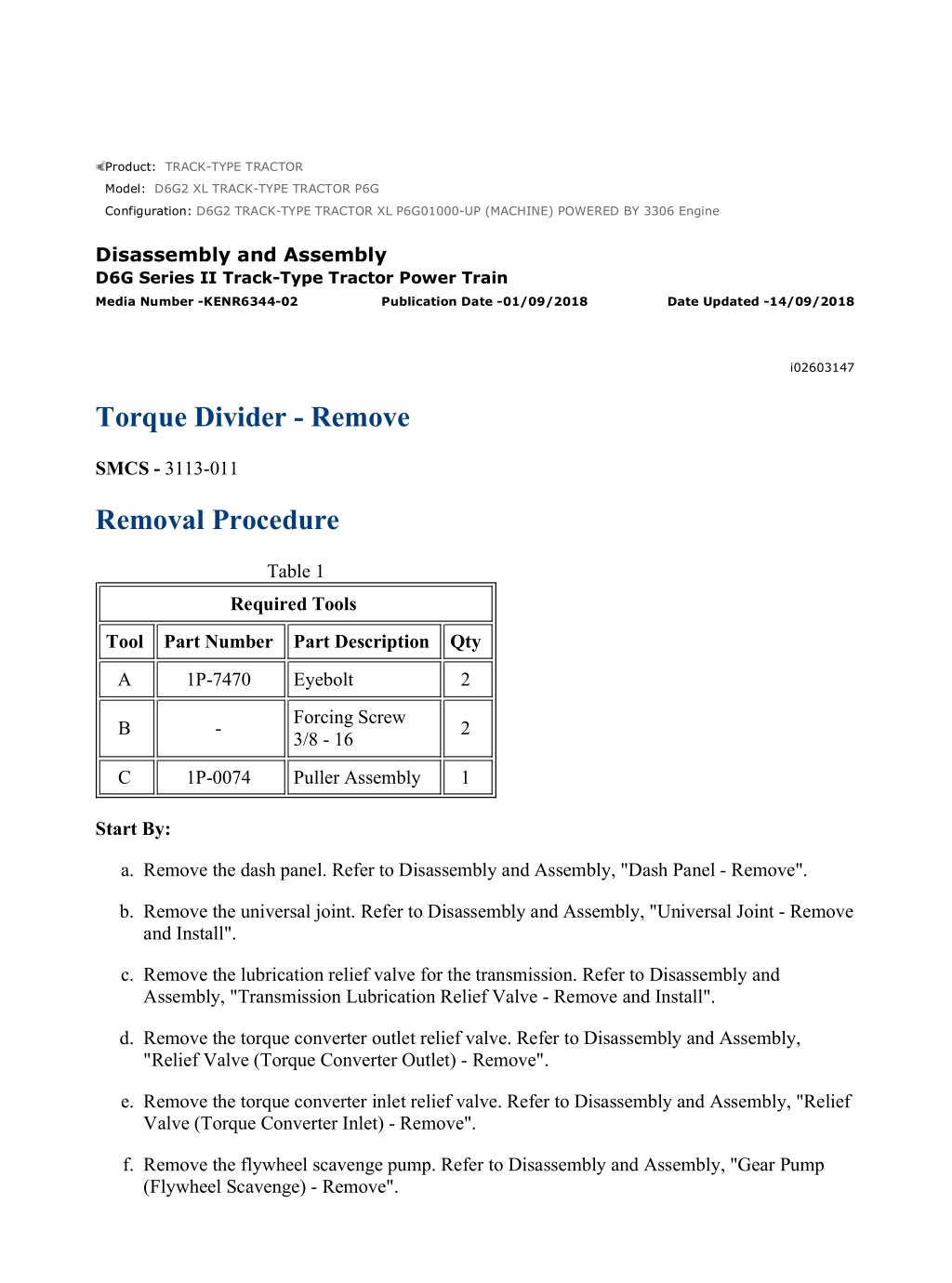
D6G2 TRACK-TYPE TRACTOR XL P6G01000-UP (MACHINE) POWERED BY 3... 1/4 Product: TRACK-TYPE TRACTOR Model: D6G2 XL TRACK-TYPE TRACTOR P6G Configuration: D6G2 TRACK-TYPE TRACTOR XL P6G01000-UP (MACHINE) POWERED BY 3306 Engine Disassembly and Assembly D6G Series II Track-Type Tractor Power Train Media Number -KENR6344-02 Publication Date -01/09/2018 Date Updated -14/09/2018 i02603147 Torque Divider - Remove SMCS - 3113-011 Removal Procedure Table 1 Required Tools Tool Part Number Part Description Qty A 1P-7470 Eyebolt 2 Forcing Screw 3/8 - 16 B - 2 C 1P-0074 Puller Assembly 1 Start By: a. Remove the dash panel. Refer to Disassembly and Assembly, "Dash Panel - Remove". b. Remove the universal joint. Refer to Disassembly and Assembly, "Universal Joint - Remove and Install". c. Remove the lubrication relief valve for the transmission. Refer to Disassembly and Assembly, "Transmission Lubrication Relief Valve - Remove and Install". d. Remove the torque converter outlet relief valve. Refer to Disassembly and Assembly, "Relief Valve (Torque Converter Outlet) - Remove". e. Remove the torque converter inlet relief valve. Refer to Disassembly and Assembly, "Relief Valve (Torque Converter Inlet) - Remove". f. Remove the flywheel scavenge pump. Refer to Disassembly and Assembly, "Gear Pump (Flywheel Scavenge) - Remove". https://127.0.0.1/sisweb/sisweb/techdoc/techdoc_print_page.jsp?returnurl=/sisw... 2022/1/7
D6G2 TRACK-TYPE TRACTOR XL P6G01000-UP (MACHINE) POWERED BY 3... 2/4 Note: Put identification marks on all lines, on all hoses, on all wires, and on all tubes for installation purposes. Plug all lines, all hoses and all tubes. This helps to prevent fluid loss and this helps to keep contaminants from entering the system. Illustration 1 g01305707 1. Disconnect tube assembly (1). Illustration 2 g01303305 https://127.0.0.1/sisweb/sisweb/techdoc/techdoc_print_page.jsp?returnurl=/sisw... 2022/1/7
D6G2 TRACK-TYPE TRACTOR XL P6G01000-UP (MACHINE) POWERED BY 3... 3/4 Illustration 3 g01303595 2. Remove tube assembly (2). Attach Tooling (A) and a suitable lifting device to torque divider (4). The weight of torque divider (4) is approximately 135 kg (298 lb). Remove nuts (3) that hold torque divider (4) to the flywheel housing. 3. Use Tooling (B) in order to separate torque divider (4) from the flywheel housing. Place a wire around carrier assembly (5) before torque divider (4) is removed from the machine. This will hold carrier assembly (5) in position when torque divider (4) is removed. Illustration 4 g01303735 Personal injury can result from being struck by parts propelled by a released spring force. Make sure to wear all necessary protective equipment. https://127.0.0.1/sisweb/sisweb/techdoc/techdoc_print_page.jsp?returnurl=/sisw... 2022/1/7
https://www.ebooklibonline.com Hello dear friend! Thank you very much for reading. Enter the link into your browser. The full manual is available for immediate download. https://www.ebooklibonline.com
D6G2 TRACK-TYPE TRACTOR XL P6G01000-UP (MACHINE) POWERED BY 3... 4/4 Follow the recommended procedure and use all recommended tooling to release the spring force. 4. Remove ring (6) and gear (7). Illustration 5 g01303739 5. Remove springs (8). Remove ring (9). Illustration 6 g01303741 6. Use Tooling (C) in order to remove bearing (10). https://127.0.0.1/sisweb/sisweb/techdoc/techdoc_print_page.jsp?returnurl=/sisw... 2022/1/7
D6G2 TRACK-TYPE TRACTOR XL P6G01000-UP (MACHINE) POWERED BY 3... 1/11 Product: TRACK-TYPE TRACTOR Model: D6G2 XL TRACK-TYPE TRACTOR P6G Configuration: D6G2 TRACK-TYPE TRACTOR XL P6G01000-UP (MACHINE) POWERED BY 3306 Engine Disassembly and Assembly D6G Series II Track-Type Tractor Power Train Media Number -KENR6344-02 Publication Date -01/09/2018 Date Updated -14/09/2018 i02604941 Torque Divider - Disassemble SMCS - 3113-015 Disassembly Procedure Table 1 Required Tools Tool Part Number Part Description Qty A 9S-9152 Bearing Puller Attachment 1 B 8H-0663 Bearing Puller Attachment 1 C 1P-0510 Driver Group 1 D 1P-0520 Driver Group 1 E 2P-8312 Retaining Ring Pliers 1 3/8 inch - 16 NC Forcing Bolt F - 2 G 1P-7405 Eyebolt 2 Start By: a. Remove the torque divider. Refer to Disassembly and Assembly, "Torque Divider - Remove". NOTICE Care must be taken to ensure that fluids are contained during performance of inspection, maintenance, testing, adjusting and repair of the product. Be prepared to collect the fluid with suitable containers https://127.0.0.1/sisweb/sisweb/techdoc/techdoc_print_page.jsp?returnurl=/sisw... 2022/1/7
D6G2 TRACK-TYPE TRACTOR XL P6G01000-UP (MACHINE) POWERED BY 3... 2/11 before opening any compartment or disassembling any component containing fluids. Refer to Special Publication, NENG2500, "Caterpillar Dealer Service Tool Catalog" for tools and supplies suitable to collect and contain fluids on Caterpillar products. Dispose of all fluids according to local regulations and mandates. Illustration 1 g00330195 1. Remove carrier assembly (1). Illustration 2 g00330196 2. Disassemble the carrier assembly. Use the following steps. a. Remove bolt (2), the lock and shaft assembly (3). b. Remove gear (5). Remove washer (4) from the top and bottom of the gear. Remove needle bearing (6). c. Remove the other two gears from the carrier. Use Steps 2.a and 2.b. https://127.0.0.1/sisweb/sisweb/techdoc/techdoc_print_page.jsp?returnurl=/sisw... 2022/1/7
D6G2 TRACK-TYPE TRACTOR XL P6G01000-UP (MACHINE) POWERED BY 3... 3/11 Illustration 3 g00330197 3. Place torque divider (7) on suitable blocks. 4. Remove shaft assembly (8). Illustration 4 g00330198 5. Remove bolt (9), washer (10) and flange (11). Illustration 5 g00330200 6. Remove ring (12). https://127.0.0.1/sisweb/sisweb/techdoc/techdoc_print_page.jsp?returnurl=/sisw... 2022/1/7
D6G2 TRACK-TYPE TRACTOR XL P6G01000-UP (MACHINE) POWERED BY 3... 4/11 Illustration 6 g00330201 7. Remove bearing race (13) by using Tooling (A) and a suitable press. Illustration 7 g00330202 8. Remove bearing race (14) by using Tooling (B) and a suitable press. Illustration 8 g00330303 9. Remove bolts (15). https://127.0.0.1/sisweb/sisweb/techdoc/techdoc_print_page.jsp?returnurl=/sisw... 2022/1/7
D6G2 TRACK-TYPE TRACTOR XL P6G01000-UP (MACHINE) POWERED BY 3... 5/11 Illustration 9 g01303900 10. Install Tooling (G) and a suitable lifting device to cover assembly (16). The weight of cover assembly (16) is approximately 52 kg (115 lb). 11. Use Tooling (F) in order to loosen cover assembly (16). Remove cover assembly (16). Illustration 10 g01303908 12. Remove O-ring seal (18). 13. Remove bolt (17) and washers. Remove another bolt and another washer that is 180 degrees from bolt (17). Drain the oil from the torque divider through the bolt holes. 14. Remove remaining bolts (17). https://127.0.0.1/sisweb/sisweb/techdoc/techdoc_print_page.jsp?returnurl=/sisw... 2022/1/7
D6G2 TRACK-TYPE TRACTOR XL P6G01000-UP (MACHINE) POWERED BY 3... 6/11 Illustration 11 g01303911 15. Install Tooling (F) in impeller wheel (19). Attach Tooling (G) and a suitable lifting device to impeller wheel (19). The weight of the impeller wheel (19) is approximately 24 kg (53 lb). Use Tooling (F) in order to loosen impeller wheel (19). Use the suitable lifting device in order to remove impeller wheel (19). Illustration 12 g01303923 16. Remove bolts (20) and stator assembly (21). Note: Do not use a large amount of force when the stator assembly is removed from the impeller wheel. Use an equal amount of force around the stator in order to loosen the stator assembly. Illustration 13 g01303933 17. Put the impeller wheel on suitable blocks. Use Tooling (C) in order to remove carrier assembly (22) from impeller wheel (19). 18. Remove lip seal (23) from the carrier assembly. https://127.0.0.1/sisweb/sisweb/techdoc/techdoc_print_page.jsp?returnurl=/sisw... 2022/1/7
D6G2 TRACK-TYPE TRACTOR XL P6G01000-UP (MACHINE) POWERED BY 3... 7/11 Illustration 14 g00330629 19. Remove ring (24). Illustration 15 g00330630 20. Turn the carrier assembly upside-down. Remove bearing (25) with a hammer and with a suitable punch. 21. Remove seal rings (26). 22. Remove sleeve (27). The sleeve is the oil distributor. Illustration 16 g00330631 https://127.0.0.1/sisweb/sisweb/techdoc/techdoc_print_page.jsp?returnurl=/sisw... 2022/1/7
D6G2 TRACK-TYPE TRACTOR XL P6G01000-UP (MACHINE) POWERED BY 3... 8/11 23. Remove bolts (28) and gear (29). Illustration 17 g00330632 24. Invert the impeller and remove carrier assembly (30). Illustration 18 g01303945 25. Use Tooling (D) in order to remove bearing (31) from carrier (30). Illustration 19 g01303962 26. Remove retaining ring (32) by using Tooling (E). https://127.0.0.1/sisweb/sisweb/techdoc/techdoc_print_page.jsp?returnurl=/sisw... 2022/1/7
D6G2 TRACK-TYPE TRACTOR XL P6G01000-UP (MACHINE) POWERED BY 3... 9/11 Illustration 20 g01303965 27. Invert the housing assembly. 28. Use Tooling (F) in order to make a separation of the turbine from the housing. Illustration 21 g00330637 29. Remove pins (33) with a hammer and a suitable punch. Put ring (34) under compression and remove gear (35). Illustration 22 g00330638 30. Remove ring (34). https://127.0.0.1/sisweb/sisweb/techdoc/techdoc_print_page.jsp?returnurl=/sisw... 2022/1/7
D6G2 TRACK-TYPE TRACTOR XL P6G01000-UP (MACHINE) POWERED BY... 10/11 31. Remove carrier (36) and seal ring (37). 32. Remove bearings (38). Illustration 23 g00330639 33. Remove housing (39). Remove spacer (40). Illustration 24 g00330683 34. Remove bolts (41) and retainer (42). Illustration 25 g00330684 https://127.0.0.1/sisweb/sisweb/techdoc/techdoc_print_page.jsp?returnurl=/sisw... 2022/1/7
D6G2 TRACK-TYPE TRACTOR XL P6G01000-UP (MACHINE) POWERED BY... 11/11 35. Remove retaining ring (43) that holds bearing (44) in position. Illustration 26 g00330685 36. Use Tooling (D) in order to remove bearing (44). https://127.0.0.1/sisweb/sisweb/techdoc/techdoc_print_page.jsp?returnurl=/sisw... 2022/1/7
D6G2 TRACK-TYPE TRACTOR XL P6G01000-UP (MACHINE) POWERED BY 3... 1/16 Product: TRACK-TYPE TRACTOR Model: D6G2 XL TRACK-TYPE TRACTOR P6G Configuration: D6G2 TRACK-TYPE TRACTOR XL P6G01000-UP (MACHINE) POWERED BY 3306 Engine Disassembly and Assembly D6G Series II Track-Type Tractor Power Train Media Number -KENR6344-02 Publication Date -01/09/2018 Date Updated -14/09/2018 i02605138 Torque Divider - Assemble SMCS - 3113-016 Assembly Procedure Table 1 Required Tools Tool Part Number Part Description Qty C 1P-0510 Driver Group 1 D 1P-0520 Driver Group 1 E 2P-8312 Retaining Ring Pliers 1 12.7 mm (0.5 inch) Steel Rods 457.2 mm (18 inch) Long H - 2 J - 3/8 - 16 Guide Studs 2 K 8S-2328 Indicator Group 1 L 1P-0808 Multipurpose Grease 1 NOTICE Keep all parts clean from contaminants. Contaminants may cause rapid wear and shortened component life. https://127.0.0.1/sisweb/sisweb/techdoc/techdoc_print_page.jsp?returnurl=/sisw... 2022/1/8
D6G2 TRACK-TYPE TRACTOR XL P6G01000-UP (MACHINE) POWERED BY 3... 2/16 Note: Check the condition of all seals and of all components. If any parts are worn or damaged, use new parts for replacement. Illustration 1 g01303994 Illustration 2 g00330684 1. Install retaining ring (43) in bearing (44) for the housing. Install bearing (44) in the housing by using Tooling (D). Illustration 3 g00330683 https://127.0.0.1/sisweb/sisweb/techdoc/techdoc_print_page.jsp?returnurl=/sisw... 2022/1/8
D6G2 TRACK-TYPE TRACTOR XL P6G01000-UP (MACHINE) POWERED BY 3... 3/16 2. Position retainer (42) and install bolts (41). Tighten the bolts to a torque of 46 3 N m (34 2 lb ft). Illustration 4 g01303997 3. Check the clearance between the housing and the turbine. Use the following steps. a. Put spacer (40) in position on the bearing in the housing. Illustration 5 g01303998 b. Put the turbine in position in the housing. Fasten Tooling (K) to the housing. c. Move the turbine 180 degrees away from Tooling (K) until the turbine makes contact with the housing. Adjust the dial indicator to zero. Move the turbine in order to make contact with the opposite side of the housing. Measure the distance and record the distance between the two positions. d. Check the clearance between the housing and the turbine at three additional locations on the housing. Use Steps 3.a through 3.c to check the clearance. Record each of the measurements. The clearance across the new diameter must be 1.02 to 1.52 mm (0.040 inch to .060 inch). The maximum permissible clearance across the diameters must not exceed 2.29 mm (0.090 inch). e. The running clearance is half of the measured distances in Steps 3.a through 3.c. https://127.0.0.1/sisweb/sisweb/techdoc/techdoc_print_page.jsp?returnurl=/sisw... 2022/1/8
D6G2 TRACK-TYPE TRACTOR XL P6G01000-UP (MACHINE) POWERED BY 3... 4/16 Illustration 6 g01304004 4. Check the clearance between the impeller wheel and the stator assembly. Use the following steps. a. Put the impeller wheel on a flat surface. Place Tooling (H) across the impeller wheel. b. Put the stator assembly on the steel rods. Illustration 7 g01304007 c. Put Tooling (K) in the position. Hold the impeller wheel and turn the stator assembly to 180 degrees. Adjust the dial indicator to zero. Move the stator assembly to the opposite side of the impeller wheel until the stator assembly makes contact with the impeller wheel. Make a record of the distance measured. d. Check the clearance in two additional positions around the impeller wheel. Move the stator assembly around the impeller wheel approximately 60 degrees at each check. Record each measurement. The clearance across the new diameter must be 1.17 mm to 1.32 mm (0.046 inch to 0.052 inch). The maximum permissible clearance across the diameter must not exceed 1.54 mm (0.061 inch). https://127.0.0.1/sisweb/sisweb/techdoc/techdoc_print_page.jsp?returnurl=/sisw... 2022/1/8
D6G2 TRACK-TYPE TRACTOR XL P6G01000-UP (MACHINE) POWERED BY 3... 5/16 Illustration 8 g01304070 5. Check the clearance between the turbine and stator assembly. Use the following steps. a. Install four 6.35 mm (0.250 inch) flat washers in Location (X) . Illustration 9 g01304071 b. Position the stator assembly on the washers and position Tooling (K). c. Hold the turbine in position and move the stator assembly away from Tooling (K) until the stator assembly makes contact with the turbine. Adjust Tooling (K) to zero. Move the stator assembly toward Tooling (K) until the stator assembly makes contact with the turbine. Make a record of the distance measured. d. Check the clearance in two additional positions around the turbine. Move the turbine around the stator assembly approximately 60 degrees at each check. Record each measurement. The clearance across the new diameter must be 1.76 mm to 1.94 mm (0.069 inch to 0.076 inch). The maximum permissible clearance across the diameter must not exceed 2.15 mm (0.085 inch). https://127.0.0.1/sisweb/sisweb/techdoc/techdoc_print_page.jsp?returnurl=/sisw... 2022/1/8
D6G2 TRACK-TYPE TRACTOR XL P6G01000-UP (MACHINE) POWERED BY 3... 6/16 Illustration 10 g00330638 Illustration 11 g00331526 6. Raise the temperature of carrier (36). Install carrier (36). Install seal ring (37) on the carrier. Use Tooling (C) in order to install bearing (38). Install bearing (38) so that bearing (38) is flush with the outside of the flange assembly. Install ring (34). Illustration 12 g00331526 7. Use Tooling (C) to install the upper bearing in the flange assembly. Install the bearing so that the bearing is flush with the outside edge of the flange assembly. https://127.0.0.1/sisweb/sisweb/techdoc/techdoc_print_page.jsp?returnurl=/sisw... 2022/1/8
D6G2 TRACK-TYPE TRACTOR XL P6G01000-UP (MACHINE) POWERED BY 3... 7/16 Illustration 13 g00331527 8. Use Tooling (C) in order to install the lower bearing in the flange assembly . Install the bearing so that the bearing is 25.4 mm (1.00 inch) below the outside machined surface of the flange assembly. Illustration 14 g01304084 9. Compress ring (34) and install gear (35). Make sure that ring (34) is in the groove of gear (35). https://127.0.0.1/sisweb/sisweb/techdoc/techdoc_print_page.jsp?returnurl=/sisw... 2022/1/8
D6G2 TRACK-TYPE TRACTOR XL P6G01000-UP (MACHINE) POWERED BY 3... 8/16 Illustration 15 g01304088 10. Use a hammer and a punch to install two pins (33) in order to hold ring (34) in position. Illustration 16 g01304098 11. Put the flange assembly on a suitable block. Fasten a suitable lifting device to housing (39) and position housing (39) over the flange assembly. Use a hammer and a brass punch to seat the bearing. Install spacer (40) and the turbine. https://127.0.0.1/sisweb/sisweb/techdoc/techdoc_print_page.jsp?returnurl=/sisw... 2022/1/8
Suggest: For more complete manuals. Please go to the home page. https://www.ebooklibonline.com If the above button click is invalid. Please download this document first, and then click the above link to download the complete manual. Thank you so much for reading
D6G2 TRACK-TYPE TRACTOR XL P6G01000-UP (MACHINE) POWERED BY 3... 9/16 Illustration 17 g01303962 12. Install ring (32) with Tooling (E). Illustration 18 g01304119 13. Install the retaining ring on bearing (31). Note: The retaining ring is not in the center of bearing (31). 14. Install bearing (31) in the carrier (30) by using Tooling (D). The bearing is installed with the longest distance from the retaining ring to the edge of the bearing first. Make sure that the retaining ring contacts the carrier after installation. Illustration 19 g01304139 15. Position carrier (30) in position in the impeller wheel. https://127.0.0.1/sisweb/sisweb/techdoc/techdoc_print_page.jsp?returnurl=/sisw... 2022/1/8
D6G2 TRACK-TYPE TRACTOR XL P6G01000-UP (MACHINE) POWERED BY... 10/16 Illustration 20 g01304143 Illustration 21 g00330631 16. Invert the impeller wheel. Position drive gear (29) and install bolts (28). Tighten bolts (28) to torque of 46 3 N m (34 2 lb ft). Illustration 22 g01304148 17. Lower the temperature of the bearing . Use Tooling (C) to install the bearing in carrier (22). Make sure that the bearing makes contact with the bottom of the counterbore in the carrier. Install the retaining ring that holds the bearing in position in the carrier. https://127.0.0.1/sisweb/sisweb/techdoc/techdoc_print_page.jsp?returnurl=/sisw... 2022/1/8
https://www.ebooklibonline.com Hello dear friend! Thank you very much for reading. Enter the link into your browser. The full manual is available for immediate download. https://www.ebooklibonline.com


