Caterpillar Cat CS78B Vibratory Soil Compactor (Prefix 513) Service Repair Manual Instant Download (51300001 and up)
Please open the website below to get the complete manualnn// n
Download Presentation

Please find below an Image/Link to download the presentation.
The content on the website is provided AS IS for your information and personal use only. It may not be sold, licensed, or shared on other websites without obtaining consent from the author. Download presentation by click this link. If you encounter any issues during the download, it is possible that the publisher has removed the file from their server.
E N D
Presentation Transcript
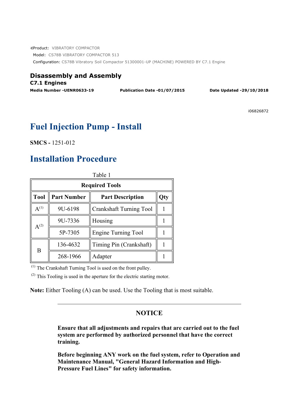
CS78B Vibratory Soil Compactor 51300001-UP (MACHINE) POWERED BY C7.1 E... 1/14 Product: VIBRATORY COMPACTOR Model: CS78B VIBRATORY COMPACTOR 513 Configuration: CS78B Vibratory Soil Compactor 51300001-UP (MACHINE) POWERED BY C7.1 Engine Disassembly and Assembly C7.1 Engines Media Number -UENR0633-19 Publication Date -01/07/2015 Date Updated -29/10/2018 i06826872 Fuel Injection Pump - Install SMCS - 1251-012 Installation Procedure Table 1 Required Tools Tool Part Number Part Description Qty A(1) 9U-6198 Crankshaft Turning Tool 1 9U-7336 Housing 1 A(2) 5P-7305 Engine Turning Tool 1 136-4632 Timing Pin (Crankshaft) 1 B 268-1966 Adapter 1 (1)The Crankshaft Turning Tool is used on the front pulley. (2)This Tooling is used in the aperture for the electric starting motor. Note: Either Tooling (A) can be used. Use the Tooling that is most suitable. NOTICE Ensure that all adjustments and repairs that are carried out to the fuel system are performed by authorized personnel that have the correct training. Before beginning ANY work on the fuel system, refer to Operation and Maintenance Manual, "General Hazard Information and High- Pressure Fuel Lines" for safety information. https://127.0.0.1/sisweb/sisweb/techdoc/techdoc_print_page.jsp?returnurl=/sis... 2022/5/25
CS78B Vibratory Soil Compactor 51300001-UP (MACHINE) POWERED BY C7.1 E... 2/14 Refer to System Operation, Testing and Adjusting, "Cleanliness of Fuel System Components" for detailed information on the standards of cleanliness that must be observed during ALL work on the fuel system. NOTICE Ensure that wiring harness are correctly routed and the cable straps are not over tightened. Over tightening of the cable straps will damage the wiring harness convoluting. Illustration 1 g06132053 1. If necessary, follow Step 1.a through Step 1.d to install bracket (31) to fuel injection pump (19). a. Position fuel injection pump (19) in a suitable stand. b. Position bracket (31) onto fuel injection pump (19). Ensure that the bracket is correctly orientated. https://127.0.0.1/sisweb/sisweb/techdoc/techdoc_print_page.jsp?returnurl=/sis... 2022/5/25
CS78B Vibratory Soil Compactor 51300001-UP (MACHINE) POWERED BY C7.1 E... 3/14 c. Install bolts (30) hand tight. d. Tighten bolts (30) to a torque of 22 N m (195 lb in). 2. If necessary, install flow control valve (12). Refer to Disassembly and Assembly, "Flow Control Valve - Remove and Install" for the correct procedure. Illustration 2 g06136408 The Angle (Y) should be 43 degrees. The Angle (Z) should be 18 degrees 3. Position key (35) on the shaft on fuel injection pump (19) in the position as shown in Illustration 2 4. Install a new O-ring seal (28) to fuel injection pump (19). Ensure that the O-ring seal is correctly installed to the groove in the fuel injection pump. https://127.0.0.1/sisweb/sisweb/techdoc/techdoc_print_page.jsp?returnurl=/sis... 2022/5/25
https://www.ebooklibonline.com Hello dear friend! Thank you very much for reading. Enter the link into your browser. The full manual is available for immediate download. https://www.ebooklibonline.com
CS78B Vibratory Soil Compactor 51300001-UP (MACHINE) POWERED BY C7.1 E... 4/14 Illustration 3 g03674811 5. Use Tooling (A) to rotate the crankshaft so that number one piston is at Top Dead Center Position on the compression stroke. 6. If necessary, install Tooling (B) to the lock the crankshaft in the correct position. Note: Do not use excessive force to install Tooling (B). Do not use Tooling (B) to hold the crankshaft during repairs. 7. Remove Tooling (B) from the crankshaft. Use Tooling (A) to rotate the crankshaft in a counter clockwise direction by 80 degrees. Refer to Illustration 3 for the correct positioning. https://127.0.0.1/sisweb/sisweb/techdoc/techdoc_print_page.jsp?returnurl=/sis... 2022/5/25
CS78B Vibratory Soil Compactor 51300001-UP (MACHINE) POWERED BY C7.1 E... 5/14 Illustration 4 g06136413 https://127.0.0.1/sisweb/sisweb/techdoc/techdoc_print_page.jsp?returnurl=/sis... 2022/5/25
CS78B Vibratory Soil Compactor 51300001-UP (MACHINE) POWERED BY C7.1 E... 6/14 Illustration 5 g06131558 https://127.0.0.1/sisweb/sisweb/techdoc/techdoc_print_page.jsp?returnurl=/sis... 2022/5/25
CS78B Vibratory Soil Compactor 51300001-UP (MACHINE) POWERED BY C7.1 E... 7/14 Illustration 6 g06136427 8. Inspect the bore in front housing (29) for damage. If the bore is damaged, replace the front housing. Refer to Disassembly and Assembly, "Housing (Front) - Remove" and Disassembly and Assembly, "Housing (Front) - Install" for the correct procedure 9. Carefully install fuel injection pump (19) to front housing (29). Ensure that the bore in the front housing is not damaged as the fuel injection pump is installed. Note: The fuel injection pump should be supported by hand as the bolts are installed. 10. Ensure that key (35) aligns correctly with fuel injection pump gear (3). Ensure that the fuel injection pump gear is correctly seated onto fuel injection pump shaft (4). Ensure that the key is not dislodged from fuel injection pump shaft (4) as fuel injection pump (19) is installed into the front housing (29). 11. Install bolts (30) to fuel injection pump (19) hand tight. 12. Install a new spring washer (6) (not shown) and install nut (5) hand tight. https://127.0.0.1/sisweb/sisweb/techdoc/techdoc_print_page.jsp?returnurl=/sis... 2022/5/25
CS78B Vibratory Soil Compactor 51300001-UP (MACHINE) POWERED BY C7.1 E... 8/14 Illustration 7 g06136426 Tightening sequence for fuel injection pump bolts (30) https://127.0.0.1/sisweb/sisweb/techdoc/techdoc_print_page.jsp?returnurl=/sis... 2022/5/25
CS78B Vibratory Soil Compactor 51300001-UP (MACHINE) POWERED BY C7.1 E... 9/14 Illustration 8 g03675419 13. Tighten bolts (30) in the sequence shown in Illustration 7 to a torque of 44 N m (32 lb ft). 14. Use a suitable tool to hold crankshaft and tighten nut (5) to a torque of 160 N m (118 lb ft). 15. To ensure that the timing between the crankshaft, idler gear, fuel injection pump, and camshaft is correct. Use Tooling (A) to rotate the crankshaft in a clockwise direction to align the timing marks as shown in Illustration 8. If necessary, install Tooling (B) to the lock the crankshaft in the correct position. 16. Remove Tooling (B) and Tooling (A). https://127.0.0.1/sisweb/sisweb/techdoc/techdoc_print_page.jsp?returnurl=/sis... 2022/5/25
CS78B Vibratory Soil Compactor 51300001-UP (MACHINE) POWERED BY C7.1... 10/14 Illustration 9 g06136430 17. Position bracket (33) onto the cylinder block and fuel injection pump (19). Install bolts (34) to the bracket finger tight. 18. Install the nut and bolt (32) to bracket (31) and bracket (33) finger tight. 19. Tighten the nut and bolt (32) to a torque of 44 N m (32 lb ft). Note: Ensure that the fuel injection pump is not stressed as the nut and bolt for the bracket are tightened. 20. Tighten bolts (34) to a torque of 22 N m (195 lb in). Note: Ensure that the fuel injection pump is not stressed as the bolts for the bracket are tightened. https://127.0.0.1/sisweb/sisweb/techdoc/techdoc_print_page.jsp?returnurl=/sis... 2022/5/25
CS78B Vibratory Soil Compactor 51300001-UP (MACHINE) POWERED BY C7.1... 11/14 Illustration 10 g03388236 21. Install a new O-ring seal (1) to plug (2). Install the plug into Position (W) of the cylinder block. Tighten the plug to a torque of 21 N m (186 lb in). https://127.0.0.1/sisweb/sisweb/techdoc/techdoc_print_page.jsp?returnurl=/sis... 2022/5/25
CS78B Vibratory Soil Compactor 51300001-UP (MACHINE) POWERED BY C7.1... 12/14 Illustration 11 g06132014 22. Remove plug from fuel injection pump (19). Remove cap from tube assembly (20). 23. Install a new sealing washer (22) (not shown) to banjo bolt (21). Position tube assembly (20) onto fuel injection pump (19) and install the banjo bolt to the tube assembly. Install the remaining sealing washer between the tube assembly and fuel injection pump (19). 24. Tighten banjo bolt (21) to a torque of 21 N m (186 lb in). Ensure that tube assembly (20) is not stained as the banjo bolt is tightened. 25. Remove plug from fuel injection pump (19). Remove caps from tube assembly (25). 26. Install a new sealing washer (24) (not shown) to banjo bolt (23). 27. Install a new sealing washer (27) (not shown) to banjo bolt (26). 28. Position tube assembly (25) onto fuel injection pump (19). Install banjo bolt (23) to the tube assembly. Install remaining sealing washer (24) between the tube assembly and fuel injection pump (19). 29. Align tube assembly (25) onto the cylinder block. Install banjo bolt (26) to the tube assembly. Install remaining sealing washer (27) (not shown) between the tube assembly and the cylinder block. 30. Tighten banjo bolt (23) and banjo bolt (26) to a torque of 14 N m (124 lb in). Ensure that the tube assembly is not strained as the banjo bolts are tightened. https://127.0.0.1/sisweb/sisweb/techdoc/techdoc_print_page.jsp?returnurl=/sis... 2022/5/25
CS78B Vibratory Soil Compactor 51300001-UP (MACHINE) POWERED BY C7.1... 13/14 Illustration 12 g06132010 31. Install new fuel injection lines (7) to fuel injection pump (19) and the fuel manifold. Refer to Disassembly and Assembly, "Fuel Injection Lines - Install" for the correct procedure. 32. Connect harness assembly (11) to flow control valve (12). 33. Position bracket (15) for harness assembly (11) onto cylinder block. Install bolts (14) to the bracket. Tighten the bolts to a torque of 22 N m (195 lb in). 34. Install a new sealing washers (13) (not shown) to banjo bolt (16). Remove cap from tube assembly (17) and plug from fuel injection pump (19). 35. Position tube assembly (17) onto fuel injection pump (19). Install banjo bolt (16) to the tube assembly. Install remaining sealing washer (13) (not shown). 36. Tighten banjo bolt (16) to a torque of 21 N m (186 lb in). Ensure that tube assembly (17) is not stained as the banjo bolt is tightened. https://127.0.0.1/sisweb/sisweb/techdoc/techdoc_print_page.jsp?returnurl=/sis... 2022/5/25
CS78B Vibratory Soil Compactor 51300001-UP (MACHINE) POWERED BY C7.1... 14/14 37. Remove cap from connection (18). Remove plug from the tube assembly. Connect the tube assembly to the connection. 38. Install a new sealing washers (9) (not shown) to banjo bolt (8). Remove cap from tube assembly (10) and plug from fuel injection pump (19). 39. Position tube assembly (10) onto fuel injection pump (19). Install banjo bolt (8) to the tube assembly. Install remaining sealing washer (9) (not shown). Install bolt (12a) to clip for tube assembly hand tight. 40. Tighten the banjo bolt to a torque of 21 N m (186 lb in). 41. Tighten bolt (12a) to a torque of 22 N m (195 lb in). 42. Install the front cover. Refer to Disassembly and Assembly, "Front Cover - Remove and Install" for the correct procedure. 43. Install the valve mechanism cover. Refer to Disassembly and Assembly, "Valve Mechanism Cover - Remove and Install" for the correct procedure. 44. If necessary, install the crankcase breather (Filtered Breather). Refer to Disassembly and Assembly, "Crankcase Breather (Filtered Breather) - Remove" for the correct procedure. 45. If necessary, install the fuel filter base. Refer to Disassembly and Assembly, "Fuel Filter Base - Remove and Install" for the correct procedure. 46. If necessary, install the fuel priming pump. Refer to Disassembly and Assembly, "Fuel Priming Pump - Remove and Install". 47. Replace the filters for primary fuel system. Refer to Operation and Maintenance Manual, "Fuel System Primary (Water Separator) Element - Replace" for the correct procedure. 48. Replace the filters for secondary fuel system. Refer to Operation and Maintenance Manual, "Fuel System Secondary Filter - Replace" for the correct procedure. 49. Turn the fuel supply to the ON position. 50. Turn the battery disconnect switch to the ON position. 51. Remove the air from the fuel system. Refer to Operation and Maintenance Manual, "Fuel System - Prime" for the correct procedure. https://127.0.0.1/sisweb/sisweb/techdoc/techdoc_print_page.jsp?returnurl=/sis... 2022/5/25
CS78B Vibratory Soil Compactor 51300001-UP (MACHINE) POWERED BY C7.1 E... 1/5 Product: VIBRATORY COMPACTOR Model: CS78B VIBRATORY COMPACTOR 513 Configuration: CS78B Vibratory Soil Compactor 51300001-UP (MACHINE) POWERED BY C7.1 Engine Disassembly and Assembly C7.1 Engines Media Number -UENR0633-19 Publication Date -01/07/2015 Date Updated -29/10/2018 i05292315 Fuel Injection Pump Gear - Remove SMCS - 1251-011 Removal Procedure Table 1 Required Tools Tool Part Number Part Description Qty A(1) 9U-6198 Crankshaft Turning Tool 1 9U-7336 Housing 1 A(2) 5P-7305 Engine Turning Tool 1 B 230-6284 Timing Pin (Camshaft) 1 136-4632 Timing Pin (Crankshaft) 1 C 268-1966 Adapter 1 D - Puller 1 E - Bolts (M10 x 1.50 by 130 mm) 2 (1)The Crankshaft Turning Tool is used on the front pulley. (2)This Tool is used in the aperture for the electric starting motor. Start By: a. Remove the front cover. Refer to Disassembly and Assembly, "Front Cover - Remove and Install" for the correct procedure. NOTICE https://127.0.0.1/sisweb/sisweb/techdoc/techdoc_print_page.jsp?returnurl=/sis... 2022/5/25
CS78B Vibratory Soil Compactor 51300001-UP (MACHINE) POWERED BY C7.1 E... 2/5 Keep all parts clean from contaminants. Contaminants may cause rapid wear and shortened component life. NOTICE Care must be taken to ensure that fluids are contained during performance of inspection, maintenance, testing, adjusting and repair of the product. Be prepared to collect the fluid with suitable containers before opening any compartment or disassembling any component containing fluids. Dispose of all fluids according to local regulations and mandates. Note: Either Tooling (A) can be used. Use the Tooling that is most suitable. Care must be taken in order to ensure that the fuel injection pump timing is not lost during the removal of the front gear group. Carefully follow the procedure in order to remove the gear group. Illustration 1 g03383731 https://127.0.0.1/sisweb/sisweb/techdoc/techdoc_print_page.jsp?returnurl=/sis... 2022/5/25
CS78B Vibratory Soil Compactor 51300001-UP (MACHINE) POWERED BY C7.1 E... 3/5 1. Remove plug (2) from the cylinder block. Remove O-ring seal (1) from the plug. 2. Use Tooling (A) in order to rotate the crankshaft so that number one piston is at top dead center on the compression stroke. Refer to System Operation, Testing and Adjusting, "Finding Top Center Position for No.1 Piston" for the correct procedure. 3. Install Tooling (C) through Hole (W) in order to lock the crankshaft. Note: Do not use excessive force to install Tooling (C). Do not use Tooling (C) to hold the crankshaft during repairs. Illustration 2 g03383730 4. Install Tooling (B) through Hole (X) in camshaft gear (3) into the front housing. Use Tooling (B) in order to lock the camshaft in the correct position. https://127.0.0.1/sisweb/sisweb/techdoc/techdoc_print_page.jsp?returnurl=/sis... 2022/5/25
CS78B Vibratory Soil Compactor 51300001-UP (MACHINE) POWERED BY C7.1 E... 4/5 Illustration 3 g03383775 Alignment of timing marks 5. Mark gear (3), gear (4), and gear (5) in order to show alignment. Refer to Illustration 3. Note: Identification will ensure that the gears can be installed in the original alignment. 6. Loosen nut (6) for fuel pump gear (5). 7. Install Tooling (D) and Tooling (E) into the two threaded holes in fuel pump gear (5). Tighten Tooling (D) and Tooling (E) until fuel pump gear (5) is released. 8. Remove Tooling (D) and Tooling (E) from fuel pump gear (5). 9. Remove nut (6) and spring washer (7) (not shown) from fuel pump gear (5). Remove the fuel pump gear. https://127.0.0.1/sisweb/sisweb/techdoc/techdoc_print_page.jsp?returnurl=/sis... 2022/5/25
CS78B Vibratory Soil Compactor 51300001-UP (MACHINE) POWERED BY C7.1 E... 1/5 Product: VIBRATORY COMPACTOR Model: CS78B VIBRATORY COMPACTOR 513 Configuration: CS78B Vibratory Soil Compactor 51300001-UP (MACHINE) POWERED BY C7.1 Engine Disassembly and Assembly C7.1 Engines Media Number -UENR0633-19 Publication Date -01/07/2015 Date Updated -29/10/2018 i05292314 Fuel Injection Pump Gear - Install SMCS - 1251-012 Installation Procedure Table 1 Required Tools Tool Part Number Part Description Qty B 230-6284 Timing Pin (Camshaft) 1 136-4632 Timing Pin (Crankshaft) 1 C 268-1966 Adapter 1 8T-5096 Dial Indicator Gp 1 F - Magnetic Base and Stand 1 NOTICE Keep all parts clean from contaminants. Contaminants may cause rapid wear and shortened component life. NOTICE Care must be taken to ensure that fluids are contained during performance of inspection, maintenance, testing, adjusting and repair of the product. Be prepared to collect the fluid with suitable containers https://127.0.0.1/sisweb/sisweb/techdoc/techdoc_print_page.jsp?returnurl=/sis... 2022/5/25
Suggest: For more complete manuals. Please go to the home page. https://www.ebooklibonline.com If the above button click is invalid. Please download this document first, and then click the above link to download the complete manual. Thank you so much for reading
CS78B Vibratory Soil Compactor 51300001-UP (MACHINE) POWERED BY C7.1 E... 2/5 before opening any compartment or disassembling any component containing fluids. Dispose of all fluids according to local regulations and mandates. Note: Care must be taken in order to ensure that the fuel injection pump timing is not lost during the installation of the fuel pump gear. Carefully follow the procedure in order to install the fuel pump gear. Illustration 1 g03385331 1. Ensure that number one piston is at top dead center on the compression stroke. Refer to System Operation, Testing and Adjusting, "Finding Top Center Position for No.1 Piston" for the correct procedure. 2. Install Tooling (C) through Hole (W) in order to lock the crankshaft. Note: Do not use excessive force to install Tooling (C). Do not use Tooling (C) to hold the crankshaft during repairs. https://127.0.0.1/sisweb/sisweb/techdoc/techdoc_print_page.jsp?returnurl=/sis... 2022/5/25
CS78B Vibratory Soil Compactor 51300001-UP (MACHINE) POWERED BY C7.1 E... 3/5 Illustration 2 g03383730 https://127.0.0.1/sisweb/sisweb/techdoc/techdoc_print_page.jsp?returnurl=/sis... 2022/5/25
https://www.ebooklibonline.com Hello dear friend! Thank you very much for reading. Enter the link into your browser. The full manual is available for immediate download. https://www.ebooklibonline.com

