Caterpillar Cat CS78B Compactor-Vibratory Soil (Prefix M8M) Service Repair Manual Instant Download (M8M00001 and up)
Please open the website below to get the complete manualnn// n
Download Presentation

Please find below an Image/Link to download the presentation.
The content on the website is provided AS IS for your information and personal use only. It may not be sold, licensed, or shared on other websites without obtaining consent from the author. Download presentation by click this link. If you encounter any issues during the download, it is possible that the publisher has removed the file from their server.
E N D
Presentation Transcript
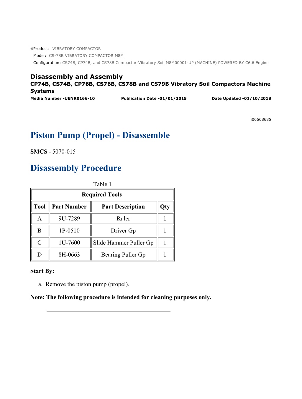
CS74B, CP74B, and CS78B Compactor-Vibratory Soil M8M00001-UP (MACHINE) ... 1/18 Product: VIBRATORY COMPACTOR Model: CS-78B VIBRATORY COMPACTOR M8M Configuration: CS74B, CP74B, and CS78B Compactor-Vibratory Soil M8M00001-UP (MACHINE) POWERED BY C6.6 Engine Disassembly and Assembly CP74B, CS74B, CP76B, CS76B, CS78B and CS79B Vibratory Soil Compactors Machine Systems Media Number -UENR0166-10 Publication Date -01/01/2015 Date Updated -01/10/2018 i06668685 Piston Pump (Propel) - Disassemble SMCS - 5070-015 Disassembly Procedure Table 1 Required Tools Tool Part Number Part Description Qty A 9U-7289 Ruler 1 B 1P-0510 Driver Gp 1 C 1U-7600 Slide Hammer Puller Gp 1 D 8H-0663 Bearing Puller Gp 1 Start By: a. Remove the piston pump (propel). Note: The following procedure is intended for cleaning purposes only. https://127.0.0.1/sisweb/sisweb/techdoc/techdoc_print_page.jsp?returnurl=/sisw... 2022/1/9
CS74B, CP74B, and CS78B Compactor-Vibratory Soil M8M00001-UP (MACHINE) ... 2/18 Illustration 1 g03643661 Personal injury can result from being struck by parts propelled by a released spring force. Make sure to wear all necessary protective equipment. Follow the recommended procedure and use all recommended tooling to release the spring force. 1. Remove cover (1) and the spring for the crossover relief valve. Illustration 2 g03643670 https://127.0.0.1/sisweb/sisweb/techdoc/techdoc_print_page.jsp?returnurl=/sisw... 2022/1/9
CS74B, CP74B, and CS78B Compactor-Vibratory Soil M8M00001-UP (MACHINE) ... 3/18 Illustration 3 g03643663 2. Remove seat (2). 3. Note the orientation of spring (3). 4. Remove O-ring seal (4) from cover (1). 5. Remove backup ring (5) from cover (1). 6. Repeat Step 1 through Step 5 for the other covers. Illustration 4 g03643697 Personal injury can result from being struck by parts propelled by a released spring force. Make sure to wear all necessary protective equipment. Follow the recommended procedure and use all recommended tooling to release the spring force. https://127.0.0.1/sisweb/sisweb/techdoc/techdoc_print_page.jsp?returnurl=/sisw... 2022/1/9
https://www.ebooklibonline.com Hello dear friend! Thank you very much for reading. Enter the link into your browser. The full manual is available for immediate download. https://www.ebooklibonline.com
CS74B, CP74B, and CS78B Compactor-Vibratory Soil M8M00001-UP (MACHINE) ... 4/18 7. Remove plug (6) for the charge relief valve. Illustration 5 g03643707 8. Remove seat (9). 9. Remove shims (8). 10. Remove spring (7). 11. Remove seal (10) from plug (6). 12. Remove O-ring seal (11) from plug (6). Illustration 6 g03643744 13. Remove nut (12). https://127.0.0.1/sisweb/sisweb/techdoc/techdoc_print_page.jsp?returnurl=/sisw... 2022/1/9
CS74B, CP74B, and CS78B Compactor-Vibratory Soil M8M00001-UP (MACHINE) ... 5/18 Illustration 7 g03643823 14. Remove O-ring seal (14) and coil assembly (13). Illustration 8 g03643756 15. Remove cartridge (16) and O-ring seal (15). Illustration 9 g03643837 16. Remove spool (17) and spring (18). https://127.0.0.1/sisweb/sisweb/techdoc/techdoc_print_page.jsp?returnurl=/sisw... 2022/1/9
CS74B, CP74B, and CS78B Compactor-Vibratory Soil M8M00001-UP (MACHINE) ... 6/18 Illustration 10 g03643856 17. Remove bolts (20) and valve assembly (19). Illustration 11 g03643863 18. Remove plate (21). Remove gasket (23) and gasket (22). 19. Remove nut (26), O-ring seal (28), and coil assembly (25). 20. Remove cartridge (27) and O-ring seal (24). 21. Repeat Step 19 to Step 20 on other side of valve assembly (19). Illustration 12 g03643895 https://127.0.0.1/sisweb/sisweb/techdoc/techdoc_print_page.jsp?returnurl=/sisw... 2022/1/9
CS74B, CP74B, and CS78B Compactor-Vibratory Soil M8M00001-UP (MACHINE) ... 7/18 Illustration 13 g03643896 Personal injury can result from being struck by parts propelled by a released spring force. Make sure to wear all necessary protective equipment. Follow the recommended procedure and use all recommended tooling to release the spring force. 22. Remove bolt (29). Remove eccentric pin (30) and O-ring seal (31). 23. Remove levers (35), draw spring (34), feedback lever (33), and shims (32). 24. Repeat Step 17 to Step 23 on the other side of the piston pump. Illustration 14 g03644388 https://127.0.0.1/sisweb/sisweb/techdoc/techdoc_print_page.jsp?returnurl=/sisw... 2022/1/9
CS74B, CP74B, and CS78B Compactor-Vibratory Soil M8M00001-UP (MACHINE) ... 8/18 Personal injury can result from being struck by parts propelled by a released spring force. Make sure to wear all necessary protective equipment. Follow the recommended procedure and use all recommended tooling to release the spring force. 25. Use Tooling (A) to measure the distance from the stud to the nut. Record the distance for assembly purposes. 26. Remove relief valve (36) and the O-ring seal. Illustration 15 g03644918 27. Remove spring assembly (37) and spool assembly (38). Illustration 16 g03644973 28. Use Tooling (A) to measure the distance from the stud to the nut. Record the distance for assembly purposes. Remove eccentric screw assembly (39). https://127.0.0.1/sisweb/sisweb/techdoc/techdoc_print_page.jsp?returnurl=/sisw... 2022/1/9
CS74B, CP74B, and CS78B Compactor-Vibratory Soil M8M00001-UP (MACHINE) ... 9/18 Illustration 17 g03644990 29. Remove O-ring seal (40), bolts (42) and plate (41). Illustration 18 g03644999 30. Remove bolts (44) and cover assembly (43). Illustration 19 g03645000 31. Remove O-ring seal (45) and retaining ring (46). https://127.0.0.1/sisweb/sisweb/techdoc/techdoc_print_page.jsp?returnurl=/sisw... 2022/1/9
CS74B, CP74B, and CS78B Compactor-Vibratory Soil M8M00001-UP (MACHIN... 10/18 Illustration 20 g03645005 32. Remove O-ring seal (47) and bearing races (48). Remove shaft assembly (49). Illustration 21 g03645013 33. Remove retaining ring (51). Use suitable press to remove bearing (52) from shaft (50). Illustration 22 g03645047 34. Remove rotating assembly (51). https://127.0.0.1/sisweb/sisweb/techdoc/techdoc_print_page.jsp?returnurl=/sisw... 2022/1/9
CS74B, CP74B, and CS78B Compactor-Vibratory Soil M8M00001-UP (MACHIN... 11/18 Illustration 23 g03645053 35. Remove bearing assemblies (52), linkage (54), and swashplate (53). Illustration 24 g06066294 36. Remove reaction plate assembly (55) and pistons (56) from barrel (57). Illustration 25 g06066296 https://127.0.0.1/sisweb/sisweb/techdoc/techdoc_print_page.jsp?returnurl=/sisw... 2022/1/9
CS74B, CP74B, and CS78B Compactor-Vibratory Soil M8M00001-UP (MACHIN... 12/18 Illustration 26 g06066297 37. Remove bearing (58), shim (59), and spring washers (60) from barrel (57). Illustration 27 g06066298 Personal injury can result from being struck by parts propelled by a released spring force. Make sure to wear all necessary protective equipment. Follow the recommended procedure and use all recommended tooling to release the spring force. 38. Place barrel (57) into a suitable press. https://127.0.0.1/sisweb/sisweb/techdoc/techdoc_print_page.jsp?returnurl=/sisw... 2022/1/9
CS74B, CP74B, and CS78B Compactor-Vibratory Soil M8M00001-UP (MACHIN... 13/18 39. Use Tooling (B) to remove retaining ring (61). Illustration 28 g03645108 40. Remove port plate (62). Illustration 29 g03645093 41. Remove bolts (64). Remove housing assembly (63) and the O-ring seal. Illustration 30 g03645119 42. Remove retaining ring (65). Use Tooling (C) to remove seal (66). https://127.0.0.1/sisweb/sisweb/techdoc/techdoc_print_page.jsp?returnurl=/sisw... 2022/1/9
CS74B, CP74B, and CS78B Compactor-Vibratory Soil M8M00001-UP (MACHIN... 14/18 Illustration 31 g03645170 Typical example. 43. Remove retaining ring (67). Illustration 32 g03645199 Typical example. 44. Remove bearing races (68) and shaft assembly (69). Illustration 33 g03645173 Typical example. 45. Remove retaining ring (70). https://127.0.0.1/sisweb/sisweb/techdoc/techdoc_print_page.jsp?returnurl=/sisw... 2022/1/9
CS74B, CP74B, and CS78B Compactor-Vibratory Soil M8M00001-UP (MACHIN... 15/18 Illustration 34 g03645188 Typical example. 46. Use suitable press and Tooling (D) to remove bearing (71). Illustration 35 g03645194 47. Repeat Step 34 through Step 40 to remove rotating group (72). Illustration 36 g03645231 48. Use Tooling (B) to remove bushings (73). https://127.0.0.1/sisweb/sisweb/techdoc/techdoc_print_page.jsp?returnurl=/sisw... 2022/1/9
CS74B, CP74B, and CS78B Compactor-Vibratory Soil M8M00001-UP (MACHIN... 16/18 Illustration 37 g03645229 49. Use Tooling (A) to measure the distance from the stud to the nut. Record the distance for assembly purposes. Illustration 38 g03645246 50. Remove bolts (74). 51. Remove nut (75). 52. Remove cover (76). Illustration 39 g03645645 https://127.0.0.1/sisweb/sisweb/techdoc/techdoc_print_page.jsp?returnurl=/sisw... 2022/1/9
CS74B, CP74B, and CS78B Compactor-Vibratory Soil M8M00001-UP (MACHIN... 17/18 53. Remove O-ring seal (77) from cover (76). Illustration 40 g03645251 54. Remove bolts (78) and cover (79). Illustration 41 g03645257 55. Remove O-ring seal (80) from cover (79). Illustration 42 g03645261 56. Remove actuator assembly (81) and O-ring seal (82). https://127.0.0.1/sisweb/sisweb/techdoc/techdoc_print_page.jsp?returnurl=/sisw... 2022/1/9
CS74B, CP74B, and CS78B Compactor-Vibratory Soil M8M00001-UP (MACHIN... 18/18 Illustration 43 g03645291 57. Remove seals (83). 58. Remove liner (84). 59. Repeat Step 49 through Step 58 for the other end of the piston pump. https://127.0.0.1/sisweb/sisweb/techdoc/techdoc_print_page.jsp?returnurl=/sisw... 2022/1/9
CS74B, CP74B, and CS78B Compactor-Vibratory Soil M8M00001-UP (MACHINE) ... 1/19 Product: VIBRATORY COMPACTOR Model: CS-78B VIBRATORY COMPACTOR M8M Configuration: CS74B, CP74B, and CS78B Compactor-Vibratory Soil M8M00001-UP (MACHINE) POWERED BY C6.6 Engine Disassembly and Assembly CP74B, CS74B, CP76B, CS76B, CS78B and CS79B Vibratory Soil Compactors Machine Systems Media Number -UENR0166-10 Publication Date -01/01/2015 Date Updated -01/10/2018 i06674297 Piston Pump (Propel) - Assemble SMCS - 5070-016 Assembly Procedure Table 1 Required Tools Tool Part Number Part Description Qty A 9U-7289 Scale 1 B 1P-0510 Driver Gp 1 D 8H-0663 Bearing Puller Gp 1 E 6V-2055 Grease 1 F 1U-6395 Grease 1 G 2P-8301 Seal Guide 1 H 135-8296 Test Ring 1 https://127.0.0.1/sisweb/sisweb/techdoc/techdoc_print_page.jsp?returnurl=/sisw... 2022/1/9
CS74B, CP74B, and CS78B Compactor-Vibratory Soil M8M00001-UP (MACHINE) ... 2/19 Illustration 1 g03645231 1. Use Tooling (B) to install bushings (73). Illustration 2 g03645291 2. Install liner (84). 3. Install seal (83). Illustration 3 g03645261 4. Install O-ring seal (82). Install actuator assembly (81). https://127.0.0.1/sisweb/sisweb/techdoc/techdoc_print_page.jsp?returnurl=/sisw... 2022/1/9
Suggest: For more complete manuals. Please go to the home page. https://www.ebooklibonline.com If the above button click is invalid. Please download this document first, and then click the above link to download the complete manual. Thank you so much for reading
CS74B, CP74B, and CS78B Compactor-Vibratory Soil M8M00001-UP (MACHINE) ... 3/19 Illustration 4 g03645257 5. Install O-ring seal (80) to cover (79). Illustration 5 g03645251 6. Install cover (79) and bolts (78). Illustration 6 g03645645 7. Install O-ring seal (77) to cover (76). https://127.0.0.1/sisweb/sisweb/techdoc/techdoc_print_page.jsp?returnurl=/sisw... 2022/1/9
CS74B, CP74B, and CS78B Compactor-Vibratory Soil M8M00001-UP (MACHINE) ... 4/19 Illustration 7 g03645246 Illustration 8 g03645229 8. Install cover (76), nut (75), and bolts (74). Use Tooling (A) to measure the distance from the stud to nut (75). Set the distance to the recorded measurement from the disassembly. 9. Repeat Step 2 through Step 8 for the other end of the piston pump. Illustration 9 g03645108 10. Install port plate (62). https://127.0.0.1/sisweb/sisweb/techdoc/techdoc_print_page.jsp?returnurl=/sisw... 2022/1/9
https://www.ebooklibonline.com Hello dear friend! Thank you very much for reading. Enter the link into your browser. The full manual is available for immediate download. https://www.ebooklibonline.com

