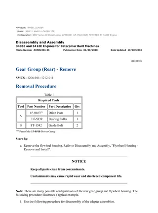
Caterpillar Cat 988F Wheel Loader (Prefix 8YG) Service Repair Manual Instant Download (8YG00001 and up)
Please open the website below to get the complete manualnn//
Download Presentation

Please find below an Image/Link to download the presentation.
The content on the website is provided AS IS for your information and personal use only. It may not be sold, licensed, or shared on other websites without obtaining consent from the author. Download presentation by click this link. If you encounter any issues during the download, it is possible that the publisher has removed the file from their server.
E N D
Presentation Transcript
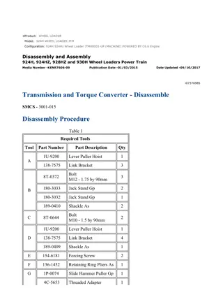
w 1/14(W) Product: WHEEL LOADER Model: 988F WHEEL LOADER 8YG Configuration: 988F Wheel Loader 8YG00001-UP (MACHINE) POWERED BY 3408 Engine Disassembly and Assembly 988F and 988F Series II Wheel Loaders Power Train Media Number -SENR5729-09 Publication Date -01/08/2008 Date Updated -18/08/2008 i02360730 Output Transfer Gears - Disassemble SMCS - 3075-015-OJ Disassembly Procedure Table 1 Required Tools Tool Part Number Part Description Qty 1H-3107 Bearing Puller 1 1H-3108 Leg 2 1H-3110 Puller Assembly 1 5F-7366 Screw 1 A 5F-7351 Nut 1 5F-7353 Washer 1 6V-3160 Puller 1 4C-4865 Manual Hydraulic Pump 1 B 5F-7353 Washer 1 6V-3160 Puller 1 4C-4865 Manual Hydraulic Pump 1 1P-1839 Bearing Puller Adapter 1 8S-6587 Adapter 1 9S-5559 Stud 1 1M-6756 Sleeve Assembly 1 https://127.0.0.1/sisweb/sisweb/techdoc/techdoc_print_page.jsp?returnurl=/sisweb/sisw... 2022/2/12
w 2/14(W) 9H-3992 Head 1 1P-9543 Nut 1 8B-7554 Puller Assembly 1 C 8B-7548 Bearing Puller 1 8H-0684 Ratchet Wrench 1 8B-7548 Bearing Puller 1 8B-7551 Puller 1 D 9S-9154 Step Plate 1 8H-0684 Ratchet Wrench 1 8B-7554 Puller Assembly 1 8B-7548 Bearing Puller 1 E 8B-7549 Leg 2 8H-0684 Ratchet Wrench 1 8B-7548 Bearing Puller 1 8B-7551 Puller 1 F 5P-4170 Step Plate 1 8H-0684 Ratchet Wrench 1 G 5B-4274 Bolt 2 Start By: A. Remove the transfer gears. Refer to Disassembly and Assembly, "Transmission from Transfer Gears - Separate". 1. Put the output transfer gears on wood blocks. 2. Remove the yoke from the bottom of the output shaft. https://127.0.0.1/sisweb/sisweb/techdoc/techdoc_print_page.jsp?returnurl=/sisweb/sisw... 2022/2/12
w 3/14(W) Illustration 1 g00513285 Note: Bolts (1) are not all the same size. Note the locations of the different bolt sizes. 3. Remove eleven bolts (1) and the washers. Illustration 2 g00513288 4. Attach a hoist to the bearing cage and transfer shaft assembly. Remove the bearing cage and transfer shaft assembly from the transfer case. The weight of the unit is 95 kg (210 lb). https://127.0.0.1/sisweb/sisweb/techdoc/techdoc_print_page.jsp?returnurl=/sisweb/sisw... 2022/2/12
https://www.ebooklibonline.com Hello dear friend! Thank you very much for reading. Enter the link into your browser. The full manual is available for immediate download. https://www.ebooklibonline.com
w 4/14(W) Illustration 3 g00513441 5. Remove bolt (3) and the retainer plate from the end of the shaft. Remove the O-ring seal from the end of the shaft. Remove yoke (2) . Remove the dirt guard from the shaft. Illustration 4 g00513452 6. Use Tooling (A) to remove the bearing cage with the bearings, the spacer and the gear from the shaft. 7. Remove the O-ring seal from the bearing cage. https://127.0.0.1/sisweb/sisweb/techdoc/techdoc_print_page.jsp?returnurl=/sisweb/sisw... 2022/2/12
w 5/14(W) Illustration 5 g00513461 8. Remove lip seal (4) from the bearing cage. Illustration 6 g00513488 9. Invert the bearing cage. Remove six bolts (5) , the washers, and retainer (6) . https://127.0.0.1/sisweb/sisweb/techdoc/techdoc_print_page.jsp?returnurl=/sisweb/sisw... 2022/2/12
w 6/14(W) Illustration 7 g00513505 10. Use Tooling (B) to remove two bearing cones and the bearing cup from the bearing cage. Illustration 8 g00513508 11. Use Tooling (C) in order to remove the other bearing cup from the bearing cage. https://127.0.0.1/sisweb/sisweb/techdoc/techdoc_print_page.jsp?returnurl=/sisweb/sisw... 2022/2/12
w 7/14(W) Illustration 9 g00513510 12. Use Tooling (D) to remove the bearing race and the inner bearing from the shaft. Illustration 10 g00513627 13. Remove bolts (7) and the washers that hold bearing cage (8) . 14. Use two bolts (7) as forcing screws to loosen bearing cage (8) . Install the two bolts in the threaded holes. Tighten the bolts evenly until the bearing cage is loose. 15. Remove bearing cage (8) and the shims from the transfer case. https://127.0.0.1/sisweb/sisweb/techdoc/techdoc_print_page.jsp?returnurl=/sisweb/sisw... 2022/2/12
w 8/14(W) Illustration 11 g00513642 16. Use Tooling (E) in order to remove the bearing cup from bearing cage (8) . Illustration 12 g00513647 17. Remove bolts (10) and the washers from bearing cage assembly (9) . 18. Use two bolts (10) as forcing screws to loosen bearing cage (9) . Install the two bolts in the threaded holes. Tighten the bolts evenly until the bearing cage is loose. 19. Remove bearing cage assembly (9) and the shims from the transfer case. https://127.0.0.1/sisweb/sisweb/techdoc/techdoc_print_page.jsp?returnurl=/sisweb/sisw... 2022/2/12
w 9/14(W) Illustration 13 g00513651 20. Remove four nuts (11) and the washers. Remove cover (12) . Remove the O-ring seal from underneath cover (12) . Illustration 14 g00513656 21. Remove O-ring seal (13) from the bearing cage assembly. 22. Use Tooling (E) in order to remove the bearing cup from the bearing cage. https://127.0.0.1/sisweb/sisweb/techdoc/techdoc_print_page.jsp?returnurl=/sisweb/sisw... 2022/2/12
w 10/14(W) Illustration 15 g00513660 23. Remove bolts (14) and the washers that hold the gear case cover to the transfer case. Illustration 16 g01179615 24. Install two bolts (14) and the washers in the gear case cover to the transfer case. 25. Use Tooling (G) to remove dowel (14A) from the gear case cover. 26. Remove two bolts (14) and the washers. 27. Repeat Steps 24 through 26 on the opposite end of the transfer case. https://127.0.0.1/sisweb/sisweb/techdoc/techdoc_print_page.jsp?returnurl=/sisweb/sisw... 2022/2/12
w 11/14(W) Illustration 17 g00513663 28. Install two 3/8" - 16 NC forged eyebolts into gear case cover (15) . Attach suitable lifting chains and a hoist to the gear case cover. Remove the cover from the transfer case. The weight of the cover is 45 kg (100 lb). Illustration 18 g00513666 29. Attach a suitable lifting sling and a hoist to gear (16) . Remove gear (16) from the transfer case. The weight of the gear is 39 kg (86 lb). https://127.0.0.1/sisweb/sisweb/techdoc/techdoc_print_page.jsp?returnurl=/sisweb/sisw... 2022/2/12
w 12/14(W) Illustration 19 g00513709 30. Use Tooling (F) in order to remove two bearing cones (17) from gear (16) . Illustration 20 g00513724 31. Attach a suitable lifting sling and a hoist to gear (18) . Remove gear (18) from the transfer case. The weight of the gear is 29 kg (64 lb). Illustration 21 g00513726 https://127.0.0.1/sisweb/sisweb/techdoc/techdoc_print_page.jsp?returnurl=/sisweb/sisw... 2022/2/12
w 13/14(W) 32. Remove two bearing cones (19) from gear (18) . 33. Use Tooling (C) to remove the two bearing cups from the transfer case. 34. Invert the transfer case. Remove the small O-ring seal from the transfer case. Illustration 22 g00513884 35. Remove bolts (20) and the washers from bearing cage assembly (21) . 36. Use two bolts (20) as forcing screws to loosen bearing cage (21) . Install the two bolts in the threaded holes. Tighten the bolts evenly until the bearing cage is loose. 37. Remove bearing cage assembly (21) from the transfer case. 38. Remove the O-ring seal from bearing cage (21) . Illustration 23 g00513743 39. Remove lip seal (22) from bearing cage (21) . https://127.0.0.1/sisweb/sisweb/techdoc/techdoc_print_page.jsp?returnurl=/sisweb/sisw... 2022/2/12
w 14/14(W) Illustration 24 g00513746 40. Use Tooling (E) to remove bearing race (23) from bearing cage (21) . Illustration 25 g00513747 41. Remove plate assembly (24) , the O-ring seal, the screen and the tube assembly from the transfer case. https://127.0.0.1/sisweb/sisweb/techdoc/techdoc_print_page.jsp?returnurl=/sisweb/sisw... 2022/2/12
w 1/12(W) Product: WHEEL LOADER Model: 988F WHEEL LOADER 8YG Configuration: 988F Wheel Loader 8YG00001-UP (MACHINE) POWERED BY 3408 Engine Disassembly and Assembly 988F and 988F Series II Wheel Loaders Power Train Media Number -SENR5729-09 Publication Date -01/08/2008 Date Updated -18/08/2008 i04058253 Output Transfer Gears - Assemble SMCS - 3075-016-OJ Assembly Procedure Table 1 Required Tools Tool Part Number Part Description Qty A 1P-0520 Driver Group 1 B 8S-2328 Hydraulic Transmission Indicator Group 1 C 6V-6640 Sealant 1 1. Verify that the magnets on the tube assembly and the screen are free of dirt and debris. Illustration 1 g00514010 https://127.0.0.1/sisweb/sisweb/techdoc/techdoc_print_page.jsp?returnurl=/sisweb/sisw... 2022/2/12
w 2/12(W) 2. Install tube assembly (1) and screen (2) in the screen housing. Illustration 2 g00514015 3. Install O-ring seal (3) and plate (4) on the screen housing. Illustration 3 g00514017 4. Lower the temperature of bearing cup (5) . Install the bearing cup in the bearing cage. https://127.0.0.1/sisweb/sisweb/techdoc/techdoc_print_page.jsp?returnurl=/sisweb/sisw... 2022/2/12
w 3/12(W) Illustration 4 g00514018 5. Install O-ring seal (6) on the bearing cage. Illustration 5 g00514020 6. Use Tooling (A) to install the lip seal in the bearing cage. The seal must contact with the counterbore in the bearing cage. The lip of the seal must face toward the inside of the bearing cage. 7. Place 1P-0808 Multipurpose Grease on the lip of the seal and on the O-ring seal. Illustration 6 g00514021 8. Install bearing cage (7) in the transfer case. Install the bolts and the washers that hold the cage in position. https://127.0.0.1/sisweb/sisweb/techdoc/techdoc_print_page.jsp?returnurl=/sisweb/sisw... 2022/2/12
w 4/12(W) Illustration 7 g00514029 9. Install O-ring seal (8) in the transfer case. Illustration 8 g00514030 10. Lower the temperature of bearing cup (9) and bearing cup (10) . Install the bearing cups in the transfer case. Illustration 9 g00514033 https://127.0.0.1/sisweb/sisweb/techdoc/techdoc_print_page.jsp?returnurl=/sisweb/sisw... 2022/2/12
w 5/12(W) 11. Heat two bearing cones (11) to a maximum temperature of 135 C (275 F). Install the bearing cones on gear (12) . Illustration 10 g00514042 12. Attach a suitable lifting sling and a hoist to gear (12) . The weight of gear (12) is 29 kg (64 lb). Place gear (12) in position in the transfer case. Illustration 11 g00514067 13. Heat two bearing cones (13) to a maximum temperature of 135 C (275 F). Install the bearing cones on gear (14) . https://127.0.0.1/sisweb/sisweb/techdoc/techdoc_print_page.jsp?returnurl=/sisweb/sisw... 2022/2/12
w 6/12(W) Illustration 12 g00514071 14. Attach a suitable lifting sling and a hoist to gear (14) . The weight of gear (14) is 39 kg (86 lb). Place gear (14) in position in the transfer case. Illustration 13 g00514077 15. Use Tooling (C) on the mating surface of the transfer case. 16. Attach a hoist to gear case cover (15) . Place the gear case cover in position on the transfer case. Install the eight bolts and the washers that hold the cover to the transfer case. https://127.0.0.1/sisweb/sisweb/techdoc/techdoc_print_page.jsp?returnurl=/sisweb/sisw... 2022/2/12
w 7/12(W) Illustration 14 g00514080 17. Lower the temperature of bearing cup (17) . Install the bearing cup in bearing cage (18) . 18. Install bearing cage (18) in the transfer case. DO NOT install the O-ring seal or the shims at this time. Install two bolts that are evenly spaced. Tighten the bolts finger tight. Illustration 15 g00514086 19. Install O-ring seal (20) on the bearing cage. Install cover (19) . Install the washers and the nuts that hold the cover in place. Illustration 16 g00514089 20. Lower the temperature of bearing cup (21) . Install bearing cup (21) in bearing cage (22) . https://127.0.0.1/sisweb/sisweb/techdoc/techdoc_print_page.jsp?returnurl=/sisweb/sisw... 2022/2/12
w 8/12(W) Illustration 17 g00514096 21. Install bearing cage (22) in the transfer case. DO NOT install the shims at this time. Install two bolts that are evenly spaced. Tighten the bolts finger tight. 22. Perform the following steps in order to properly tighten the bolts that hold bearing cage (18) . a. Tighten the bolts that hold bearing cage (18) and bearing cage (22) to a torque of 2.25 N m (20 lb in). b. Gears (12) and (14) should be rotated three times. c. Tighten the bolts that hold bearing cage (18) and bearing cage (22) to a torque of 4.5 N m (40 lb in). d. Gears (12) and (14) should be rotated three times. e. Tighten the bolts that hold bearing cage (18) and bearing cage (22) to a torque of 4.5 N m (40 lb in). 23. Measure the gap between each bearing cage and the transfer case in two different locations. 24. Average the two readings for each bearing cage. Add 0.18 mm (0.007 inch) to each dimension. This dimension is the thickness of the shim. 25. Remove bearing cage (18) and bearing cage (22) from the transfer case. 26. Install the O-ring seal on bearing cage (22) . 27. Install bearing cage (18) and bearing cage (22) with the correct thickness of shims. Install the bolts and the washers that hold the bearing cages in position. Tighten the bolts to a torque of 135 20 N m (100 15 lb ft). https://127.0.0.1/sisweb/sisweb/techdoc/techdoc_print_page.jsp?returnurl=/sisweb/sisw... 2022/2/12
w 9/12(W) Illustration 18 g00514106 28. Attach Tooling (B) to the transfer case. Check the end play of gears (12) and (14) . Move each gear up and down and record the readings. the end play must be 0.05 mm (0.002 inch) to 0.11 mm (0.004 inch). 29. If the end play is less than 0.05 mm (0.002 inch), add shims. If the end play is more than 0.11 mm (0.004 inch), remove shims. Illustration 19 g00514110 30. Heat inner bearing (23) to a maximum temperature of 135 C (275 F). Install the inner bearing on the shaft. https://127.0.0.1/sisweb/sisweb/techdoc/techdoc_print_page.jsp?returnurl=/sisweb/sisw... 2022/2/12
Suggest: For more complete manuals. Please go to the home page. https://www.ebooklibonline.com If the above button click is invalid. Please download this document first, and then click the above link to download the complete manual. Thank you so much for reading
w 10/12(W) Illustration 20 g00514111 31. Lower the temperature of the two bearing cups and bearing cones (24) . Install the bearing cups and the bearing cones in bearing cage (25) . Illustration 21 g00514114 32. Install retainer (26) on bearing cage (25) . The part number should be visible. Install the six bolts and the washers that hold the retainers in position. Tighten the bolts to a torque of 54 7 N m (40 5 lb ft). https://127.0.0.1/sisweb/sisweb/techdoc/techdoc_print_page.jsp?returnurl=/sisweb/sisw... 2022/2/12
w 11/12(W) Illustration 22 g00514118 33. Use Tooling (A) to install the lip seal in bearing cage (25) . The seal must make contact with the counterbore in the bearing cage. The lip of the seal must face toward the inside of the bearing cage. Illustration 23 g00514120 34. Place the bearing cage, the spacer, and the gear in position on a press. Install shaft (27) through the gear, the spacer, and the bearing cage with the press. Illustration 24 g00514122 35. Install the dirt guard, yoke (28) , the O-ring seal, retainer (29) , and the bolt. Tighten the bolt to a torque of 480 52 N m (350 38 lb ft). 36. Install the large O-ring seal on bearing cage (25) . Apply 1P-0808 Multipurpose Grease on the O-ring seal. https://127.0.0.1/sisweb/sisweb/techdoc/techdoc_print_page.jsp?returnurl=/sisweb/sisw... 2022/2/12
https://www.ebooklibonline.com Hello dear friend! Thank you very much for reading. Enter the link into your browser. The full manual is available for immediate download. https://www.ebooklibonline.com

