Caterpillar Cat 902 Compact Wheel Loader (Prefix 7ES) Service Repair Manual Instant Download (7ES00001 and up)
Please open the website below to get the complete manualnn//

Download Presentation

Please find below an Image/Link to download the presentation.
The content on the website is provided AS IS for your information and personal use only. It may not be sold, licensed, or shared on other websites without obtaining consent from the author. Download presentation by click this link. If you encounter any issues during the download, it is possible that the publisher has removed the file from their server.
E N D
Presentation Transcript
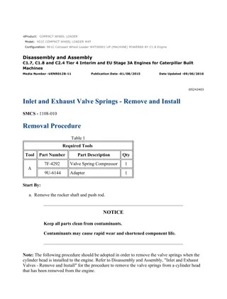
w 1/4(W) Product: COMPACT WHEEL LOADER Model: 902 COMPACT WHEEL LOADER 7ES Configuration: 902 Compact Wheel Loader 7ES00001-UP (MACHINE) POWERED BY 3024 Engine Disassembly and Assembly 3003, 3013, 3014 and 3024 Engines for Caterpillar Built Machines Media Number -SENR5027-05 Publication Date -01/05/2005 Date Updated -16/05/2005 i02399171 Inlet and Exhaust Valve Springs - Remove and Install SMCS - 1108-010 Removal Procedure Table 1 Required Tools Tool Part Number Part Description Qty A 9U-6195 Valve Spring Compressor 1 Start By: A. Remove the rocker shaft. Refer to Disassembly and Assembly, "Rocker Shaft and Pushrod - Remove". NOTICE Keep all parts clean from contaminants. Contaminants may cause rapid wear and shortened component life. Note: Before you begin the removal of the valve springs, refer to Specifications, "Cylinder Head Valves" and Testing and Adjusting, "Cylinder Head - Inspect" for appropriate information on the valve springs. NOTICE Do not turn the crankshaft while the valve springs are removed. https://127.0.0.1/sisweb/sisweb/techdoc/techdoc_print_page.jsp?returnurl=/sisweb/sisw... 2023/4/23
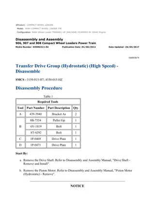
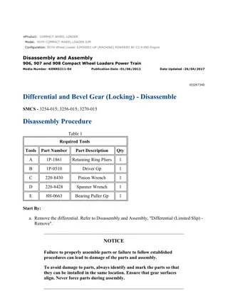
w 2/4(W) 1. Ensure that the piston is at the top center position. Illustration 1 g00825744 Personal injury can result from parts and/or covers under spring pressure. Spring force will be released when covers are removed. Be prepared to hold spring loaded covers as the bolts are loosened. 2. Use Tooling (A) to compress valve springs (1) . Remove valve keepers (2) . NOTICE Ensure that the valve spring is compressed squarely or damage to the valve stem may occur. 3. Release the pressure on Tooling (A) . Remove valve spring retainer (3) and valve springs (1) from the cylinder head. https://127.0.0.1/sisweb/sisweb/techdoc/techdoc_print_page.jsp?returnurl=/sisweb/sisw... 2023/4/23
w 3/4(W) NOTICE Do not turn the crankshaft while the valve springs are removed. Installation Procedure Table 2 Required Tools Tool Part Number Part Description Qty A 9U-6195 Valve Spring Compressor 1 NOTICE Keep all parts clean from contaminants. Contaminants may cause rapid wear and shortened component life. Illustration 2 g00825744 https://127.0.0.1/sisweb/sisweb/techdoc/techdoc_print_page.jsp?returnurl=/sisweb/sisw... 2023/4/23
https://www.ebooklibonline.com Hello dear friend! Thank you very much for reading. Enter the link into your browser. The full manual is available for immediate download. https://www.ebooklibonline.com
w 4/4(W) Improper assembly of parts that are spring loaded can cause bodily injury. To prevent possible injury, follow the established assembly procedure and wear protective equipment. 1. Place new valve springs (1) into position on the cylinder head. Note: Ensure that the closed damper coils are toward the cylinder head if double valve springs are used. 2. Install valve spring retainer (3) . 3. Use Tooling (A) to compress valve springs (1) . NOTICE Ensure that the valve spring is compressed squarely or damage to the valve stem may occur. 4. Install valve keepers (2) in order to lock the valve springs in position. 5. Release the pressure slowly on Tooling (A) . Remove Tooling (A) . Strike the top of the valves with a soft faced hammer in order to ensure that the valve keepers are properly installed. End By: Install the rocker shaft. Refer to Disassembly and Assembly, "Rocker Shaft and Pushrod - Install". https://127.0.0.1/sisweb/sisweb/techdoc/techdoc_print_page.jsp?returnurl=/sisweb/sisw... 2023/4/23
w 1/6(W) Product: COMPACT WHEEL LOADER Model: 902 COMPACT WHEEL LOADER 7ES Configuration: 902 Compact Wheel Loader 7ES00001-UP (MACHINE) POWERED BY 3024 Engine Disassembly and Assembly 3003, 3013, 3014 and 3024 Engines for Caterpillar Built Machines Media Number -SENR5027-05 Publication Date -01/05/2005 Date Updated -16/05/2005 i02015360 Inlet and Exhaust Valves - Remove and Install SMCS - 1105-010 Removal Procedure Table 1 Required Tools Tool Part Number Part Description Qty A 9U-6195 Valve Spring Compressor 1 Start By: A. Remove the cylinder head. Refer to Disassembly and Assembly, "Cylinder Head - Remove". NOTICE Keep all parts clean from contaminants. Contaminants may cause rapid wear and shortened component life. 1. Clean the bottom face of the cylinder head. Use a dial indicator to check the depth of the valves below the face of the cylinder head before the valve springs are removed. Refer to the Specifications, "Cylinder Head Valves" for the correct dimensions. 2. Place an index mark on the heads of the inlet valves and the exhaust valves for installation purposes. https://127.0.0.1/sisweb/sisweb/techdoc/techdoc_print_page.jsp?returnurl=/sisweb/sisw... 2023/4/23
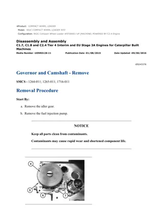
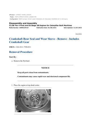
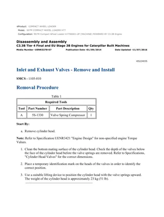
w 2/6(W) Illustration 1 g00659252 Illustration 2 g00825746 The valve spring keepers can be thrown from the valve when the valve spring compressor is released. Ensure that the valve spring keepers are properly installed on the valve stem. To help prevent personal injury, keep away from the front of the valve spring keepers and valve springs during the installation of the valves. https://127.0.0.1/sisweb/sisweb/techdoc/techdoc_print_page.jsp?returnurl=/sisweb/sisw... 2023/4/23
w 3/6(W) 3. Use Tooling (A) to compress valve springs (3) . 4. Remove two valve keepers (1) . 5. Slowly release the pressure on Tooling (A) and remove Tooling (A) . 6. Remove valve spring retainers (2) . 7. Remove valve springs (3) . 8. Remove valve stem seals (4) . 9. Remove valve spring seat washers (5) . 10. Remove inlet valves (6) and exhaust valves (6) . Removal Procedure (Alternate Method) Table 2 Required Tools Tool Part Number Part Description Qty B 5S-1330 Valve Spring Compressor 1 Follow the instructions above using Tooling (B) . Installation Procedure Table 3 Required Tools Tool Part Number Part Description Qty A 9U-6195 Valve Spring Compressor 1 https://127.0.0.1/sisweb/sisweb/techdoc/techdoc_print_page.jsp?returnurl=/sisweb/sisw... 2023/4/23
w 4/6(W) Illustration 3 g00659252 Illustration 4 g00825746 NOTICE Keep all parts clean from contaminants. Contaminants may cause rapid wear and shortened component life. https://127.0.0.1/sisweb/sisweb/techdoc/techdoc_print_page.jsp?returnurl=/sisweb/sisw... 2023/4/23
w 5/6(W) The valve spring keepers can be thrown from the valve when the valve spring compressor is released. Ensure that the valve spring keepers are properly installed on the valve stem. To help prevent personal injury, keep away from the front of the valve spring keepers and valve springs during the installation of the valves. 1. Lubricate the stems of inlet valves (6) and the stems of exhaust valves (6) with clean engine oil. 2. Install inlet valves (6) and exhaust valves (6) in the respective positions. 3. Install valve spring seat washers (5) . 4. Install new valve stem seals (4) . 5. Install valve springs (3) . Note: Install valve springs (3) on the valve spring seat washers. This is done with double valve springs. 6. Install valve spring retainers (2) . 7. Use Tooling (A) to compress valve springs (3) . 8. Install valve keepers (1) . 9. Slowly release the pressure on Tooling (A) and remove Tooling (A). Strike the top of the valves with a soft hammer in order to ensure that the valve keepers are properly installed. Note: Refer to Specifications, "Cylinder Head Valves" for more information on the inlet valves and the exhaust valves. 10. Use a dial indicator to check the depth of the new valves below the cylinder head. If the depth of the new valves is below the correct depth, the valve seat inserts must be replaced. End By: Install the cylinder head. Refer to Disassembly and Assembly, "Cylinder Head - Install". Installation Procedure (Alternate Method) Table 4 Required Tools Tool Part Number Part Description Qty B 5S-1330 Valve Spring Compressor 1 Follow the procedure above using Tooling (B). https://127.0.0.1/sisweb/sisweb/techdoc/techdoc_print_page.jsp?returnurl=/sisweb/sisw... 2023/4/23
w 1/3(W) Product: COMPACT WHEEL LOADER Model: 902 COMPACT WHEEL LOADER 7ES Configuration: 902 Compact Wheel Loader 7ES00001-UP (MACHINE) POWERED BY 3024 Engine Disassembly and Assembly 3003, 3013, 3014 and 3024 Engines for Caterpillar Built Machines Media Number -SENR5027-05 Publication Date -01/05/2005 Date Updated -16/05/2005 i01591441 Engine Oil Relief Valve - Remove and Install SMCS - 1315-010 Removal Procedure NOTICE Keep all parts clean from contaminants. Contaminants may cause rapid wear and shortened component life. NOTICE Care must be taken to ensure that fluids are contained during performance of inspection, maintenance, testing, adjusting and repair of the product. Be prepared to collect the fluid with suitable containers before opening any compartment or disassembling any component containing fluids. Refer to Special Publication, NENG2500, "Caterpillar Tools and Shop Products Guide" for tools and supplies suitable to collect and contain fluids on Caterpillar products. Dispose of all fluids according to local regulations and mandates. https://127.0.0.1/sisweb/sisweb/techdoc/techdoc_print_page.jsp?returnurl=/sisweb/sisw... 2023/4/23
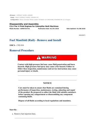
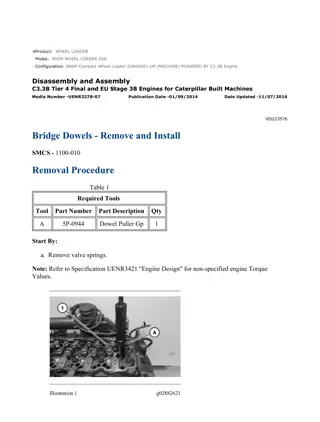
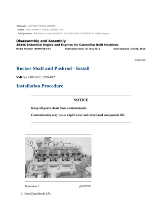
w 2/3(W) Illustration 1 g00820218 1. Remove engine oil relief valve (2) from the cylinder block. 2. Remove O-ring seal (1) from the engine oil relief valve. Installation Procedure NOTICE Keep all parts clean from contaminants. Contaminants may cause rapid wear and shortened component life. https://127.0.0.1/sisweb/sisweb/techdoc/techdoc_print_page.jsp?returnurl=/sisweb/sisw... 2023/4/23
w 3/3(W) Illustration 2 g00820218 1. Install new O-ring seal (1) on engine oil relief valve (2) . 2. Lubricate engine oil relief valve (2) with clean engine oil. 3. Install engine oil relief valve (2) in the cylinder block. Tighten the engine oil relief valve to a torque of 64 N m (47 lb ft). https://127.0.0.1/sisweb/sisweb/techdoc/techdoc_print_page.jsp?returnurl=/sisweb/sisw... 2023/4/23
w 1/4(W) Product: COMPACT WHEEL LOADER Model: 902 COMPACT WHEEL LOADER 7ES Configuration: 902 Compact Wheel Loader 7ES00001-UP (MACHINE) POWERED BY 3024 Engine Disassembly and Assembly 3003, 3013, 3014 and 3024 Engines for Caterpillar Built Machines Media Number -SENR5027-05 Publication Date -01/05/2005 Date Updated -16/05/2005 i02399591 Engine Oil Pump - Remove SMCS - 1304-011 Removal Procedure Start By: A. Remove the engine oil pan. Refer to Disassembly and Assembly, "Engine Oil Pan - Remove and Install". B. Remove the front housing. Refer to Disassembly and Assembly, "Housing (Front) - Remove". NOTICE Keep all parts clean from contaminants. Contaminants may cause rapid wear and shortened component life. NOTICE If the front housing is not installed, do not turn the crankshaft. Damage to the engine may occur. NOTICE https://127.0.0.1/sisweb/sisweb/techdoc/techdoc_print_page.jsp?returnurl=/sisweb/sisw... 2023/4/23
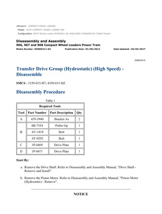
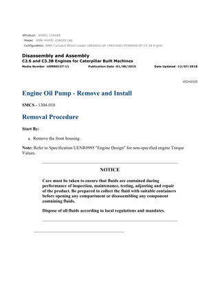
w 2/4(W) Care must be taken to ensure that fluids are contained during performance of inspection, maintenance, testing, adjusting and repair of the product. Be prepared to collect the fluid with suitable containers before opening any compartment or disassembling any component containing fluids. Refer to Special Publication, NENG2500, "Caterpillar Dealer Service Tool Catalog" for tools and supplies suitable to collect and contain fluids on Caterpillar products. Dispose of all fluids according to local regulations and mandates. Engine Oil Pump Illustration 1 g00825411 Personal injury can result from being struck by parts propelled by a released spring force. Make sure to wear all necessary protective equipment. Follow the recommended procedure and use all recommended tooling to release the spring force. https://127.0.0.1/sisweb/sisweb/techdoc/techdoc_print_page.jsp?returnurl=/sisweb/sisw... 2023/4/23
w 3/4(W) 1. Remove retaining ring (9) that retains idler gear (3) on idler hub (1) . 2. Remove the following items from idler hub (1) : Collar (8) Spring (7) Shim (6) Oil pump cover (5) Inner rotor (4) 3. Remove idler gear (3) from idler hub (1) . 4. Remove thrust washer (2) from idler hub (1) . 5. Inspect all the components for wear or damage. If components are worn or damaged, use new parts for replacement. Note: Refer to Specifications, "Engine Oil Pump" for more information. 6. If the engine oil pump has excessive buildup of sludge, inspect the oil strainer. The oil strainer can be removed by using the following procedure: a. Remove the engine oil pan. Refer to Disassembly and Assembly, "Engine Oil Pan - Remove and Install". Illustration 2 g00825406 b. Remove bolts (12) and oil strainer (13) from the cylinder block. Inspect the oil strainer for damage. If the oil strainer is damaged, use a new part for replacement. c. Remove tube assembly (11) from the cylinder block. https://127.0.0.1/sisweb/sisweb/techdoc/techdoc_print_page.jsp?returnurl=/sisweb/sisw... 2023/4/23
w 4/4(W) d. Remove O-ring seal (10) from the tube assembly. Inspect the O-ring seal for wear or damage. If the O-ring seal is worn or damaged, use a new part for replacement. Idler Hub Table 1 Required Tools Tool Part Number Part Description Qty A 1P-0074 Slide Hammer Puller 1 Illustration 3 g01037604 1. Use Tooling (A) to remove idler hub (1) from the cylinder block. https://127.0.0.1/sisweb/sisweb/techdoc/techdoc_print_page.jsp?returnurl=/sisweb/sisw... 2023/4/23
w 1/5(W) Product: COMPACT WHEEL LOADER Model: 902 COMPACT WHEEL LOADER 7ES Configuration: 902 Compact Wheel Loader 7ES00001-UP (MACHINE) POWERED BY 3024 Engine Disassembly and Assembly 3003, 3013, 3014 and 3024 Engines for Caterpillar Built Machines Media Number -SENR5027-05 Publication Date -01/05/2005 Date Updated -16/05/2005 i03121381 Engine Oil Pump - Install SMCS - 1304-012 Installation Procedure Table 1 Required Tools Tool Part Number Part Description Qty B 8T-5096 Dial Indicator Test Group 1 C (1) 256-4864 Alignment Tool C (2) 241-4232 Alignment Tool 1 D 1S-0257 Ball Peen Hammer 1 E 1P-0808 Multipurpose Grease 1 ( 1 ) 3003 engines ( 2 ) 3013, 3014 and 3024 engines NOTICE Keep all parts clean from contaminants. Contaminants may cause rapid wear and shortened component life. NOTICE https://127.0.0.1/sisweb/sisweb/techdoc/techdoc_print_page.jsp?returnurl=/sisweb/sisw... 2023/4/23
w 2/5(W) If the front housing is not installed, do not turn the crankshaft. Damage to the engine may occur. Idler Hub Illustration 1 g01198501 1. Use Tooling (C) and Tooling (D) to install idler hub (1) in the cylinder block. Engine Oil Pump https://127.0.0.1/sisweb/sisweb/techdoc/techdoc_print_page.jsp?returnurl=/sisweb/sisw... 2023/4/23
w 3/5(W) Illustration 2 g00825411 Illustration 3 g01037617 https://127.0.0.1/sisweb/sisweb/techdoc/techdoc_print_page.jsp?returnurl=/sisweb/sisw... 2023/4/23
Suggest: For more complete manuals. Please go to the home page. https://www.ebooklibonline.com If the above button click is invalid. Please download this document first, and then click the above link to download the complete manual. Thank you so much for reading
w 4/5(W) Improper assembly of parts that are spring loaded can cause bodily injury. To prevent possible injury, follow the established assembly procedure and wear protective equipment. 1. Apply Tooling (E) to the faces of inner rotor (4) and to the vanes of idler gear (3) . 2. Align Timing Marks (A) and (B) that are on idler gear (3) with the respective timing marks on gears (14) and (15) . Install idler gear (3) on idler hub (1) . 3. Install inner rotor (4) in idler gear (3) . Personal injury can result from the release of the spring force. The drive shaft, the piston, and the drive gear are under spring force. Use a press to slowly release the spring force before the components are removed. 4. Install the following items on idler hub (1) : Oil pump cover (5) Shim (6) Spring (7) Collar (8) 5. Install retaining ring (9) on idler hub (1) . 6. Use Tooling (B) in order to measure the end play of the engine oil pump. Refer to Specifications, "Engine Oil Pump". 7. If the oil strainer was removed, use the following procedure for installation: https://127.0.0.1/sisweb/sisweb/techdoc/techdoc_print_page.jsp?returnurl=/sisweb/sisw... 2023/4/23
w 5/5(W) Illustration 4 g01037619 a. Install O-ring seal (10) on tube assembly (11) . b. Install tube assembly (11) in the cylinder block. c. Install oil strainer (13) on the cylinder block and tighten bolts (12) to a torque of 11 N m (97 lb in). End By: a. Install the front housing. Refer to Disassembly and Assembly, "Housing (Front) - Install". b. Install the engine oil pan. Refer to Disassembly and Assembly, "Engine Oil Pan - Remove and Install". https://127.0.0.1/sisweb/sisweb/techdoc/techdoc_print_page.jsp?returnurl=/sisweb/sisw... 2023/4/23
https://www.ebooklibonline.com Hello dear friend! Thank you very much for reading. Enter the link into your browser. The full manual is available for immediate download. https://www.ebooklibonline.com