Caterpillar Cat 907M Compact Wheel Loader (Prefix H77) Service Repair Manual Instant Download (H7700001 and up)
Please open the website below to get the complete manualnn//

Download Presentation

Please find below an Image/Link to download the presentation.
The content on the website is provided AS IS for your information and personal use only. It may not be sold, licensed, or shared on other websites without obtaining consent from the author. Download presentation by click this link. If you encounter any issues during the download, it is possible that the publisher has removed the file from their server.
E N D
Presentation Transcript
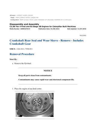
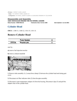
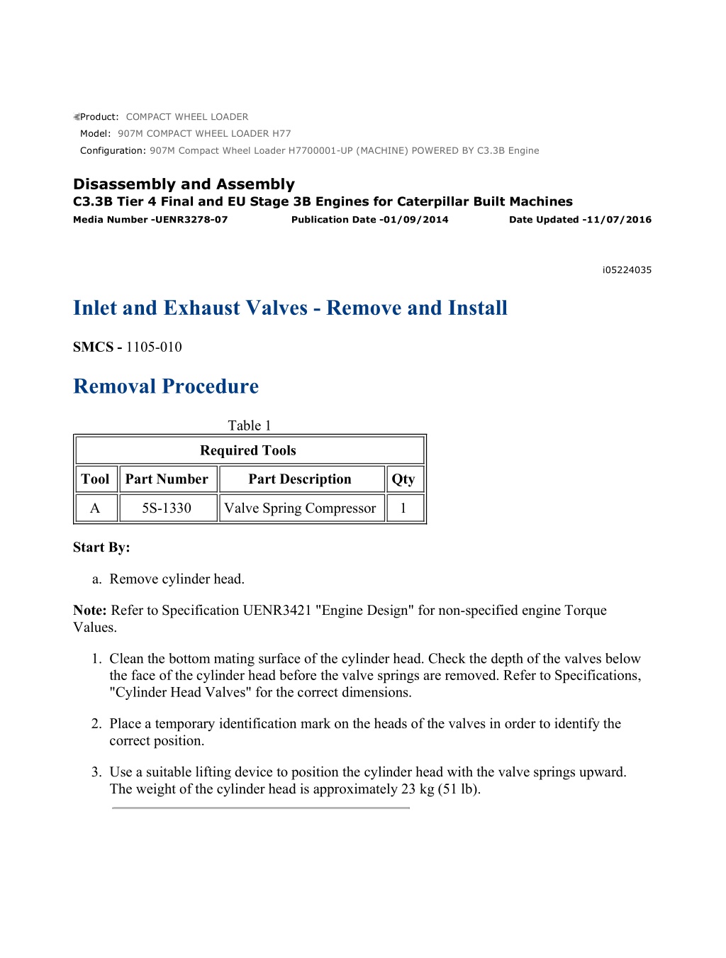
w 1/3(W) Product: COMPACT WHEEL LOADER Model: 907M COMPACT WHEEL LOADER H77 Configuration: 907M Compact Wheel Loader H7700001-UP (MACHINE) POWERED BY C3.3B Engine Disassembly and Assembly C3.3B Tier 4 Final and EU Stage 3B Engines for Caterpillar Built Machines Media Number -UENR3278-07 Publication Date -01/09/2014 Date Updated -11/07/2016 i05224035 Inlet and Exhaust Valves - Remove and Install SMCS - 1105-010 Removal Procedure Table 1 Required Tools Tool Part Number Part Description Qty A 5S-1330 Valve Spring Compressor 1 Start By: a. Remove cylinder head. Note: Refer to Specification UENR3421 "Engine Design" for non-specified engine Torque Values. 1. Clean the bottom mating surface of the cylinder head. Check the depth of the valves below the face of the cylinder head before the valve springs are removed. Refer to Specifications, "Cylinder Head Valves" for the correct dimensions. 2. Place a temporary identification mark on the heads of the valves in order to identify the correct position. 3. Use a suitable lifting device to position the cylinder head with the valve springs upward. The weight of the cylinder head is approximately 23 kg (51 lb). https://127.0.0.1/sisweb/sisweb/techdoc/techdoc_print_page.jsp?returnurl=/sisweb/siswe... 2023/5/6
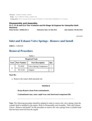
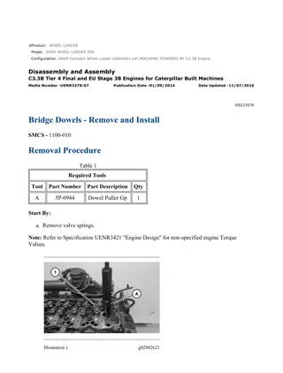
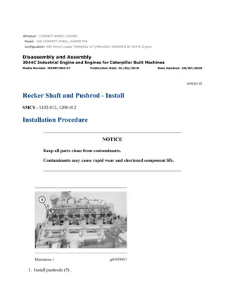
w 2/3(W) Illustration 1 g02784484 4. Install Tooling (A) in position on cylinder head (2) and compress the valve spring in order to remove inlet and exhaust valves (1). Illustration 2 g02788459 Personal injury can result from being struck by parts propelled by a released spring force. Make sure to wear all necessary protective equipment. Follow the recommended procedure and use all recommended tooling to release the spring force. NOTICE Ensure that the valve spring is compressed squarely or damage to the valve stem may occur. https://127.0.0.1/sisweb/sisweb/techdoc/techdoc_print_page.jsp?returnurl=/sisweb/siswe... 2023/5/6
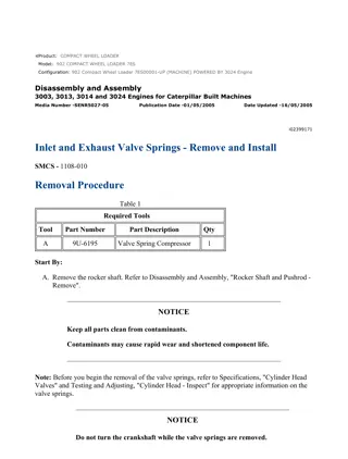
w 3/3(W) 5. Apply sufficient pressure to Tooling (A) in order to remove valve keepers (3). 6. Slowly release pressure on Tooling (A). 7. Place a temporary identification mark on valve spring (5) in order to identify the correct position. 8. Remove valve spring retainer (4). Remove valve spring (5) and inlet and exhaust valves (6). 9. Repeat Step 4 through Step 8 for the remaining valves. 10. Remove Tooling (A). Illustration 3 g02784644 11. Remove valve stem seals (7) from cylinder head (2). 12. Use a suitable lifting device in order to turn over cylinder head (2). 13. Remove the inlet and exhaust valves. Installation Procedure 1. Install inlet and exhaust valves (6) in the reverse order of removal. a. Clean all components of the cylinder head assembly. Ensure that all ports, all coolant passages, and all lubrication passages in the cylinder head are free from debris. Replace any components that are worn or damaged. b. Lubricate the stems of inlet and exhaust valves (6) with clean engine oil. Install inlet and exhaust valves (6) in the appropriate positions in the cylinder head. Check the depth of the valves below the face of the cylinder head. Refer to System Operation, Testing and Adjusting, "Valve Depth - Inspect" for more information. https://127.0.0.1/sisweb/sisweb/techdoc/techdoc_print_page.jsp?returnurl=/sisweb/siswe... 2023/5/6
https://www.ebooklibonline.com Hello dear friend! Thank you very much for reading. Enter the link into your browser. The full manual is available for immediate download. https://www.ebooklibonline.com
w 1/3(W) Product: COMPACT WHEEL LOADER Model: 907M COMPACT WHEEL LOADER H77 Configuration: 907M Compact Wheel Loader H7700001-UP (MACHINE) POWERED BY C3.3B Engine Disassembly and Assembly C3.3B Tier 4 Final and EU Stage 3B Engines for Caterpillar Built Machines Media Number -UENR3278-07 Publication Date -01/09/2014 Date Updated -11/07/2016 i05305972 Inlet and Exhaust Valve Guides - Remove and Install SMCS - 1104-010 Removal Procedure Table 1 Required Tools Tool Part Number Part Description Qty A 390-1136 Valve Guide Driver Kit 1 B 385-8470 Valve Guide Reamer 1 Start By: a. Remove the inlet and exhaust valves. Note: Refer to Specifications, "Engine Design" for non-specified engine torque values. NOTICE Removal and installation of the valve guide and valve seat must be carried out by personnel with the correct training. Also special machinery is required. For more information, refer to your authorized Caterpillar dealer. https://127.0.0.1/sisweb/sisweb/techdoc/techdoc_print_page.jsp?returnurl=/sisweb/siswe... 2023/5/6
w 2/3(W) Illustration 1 g02786036 Illustration 2 g02786037 1. Remove inlet and exhaust valve seals (1). Use Tooling (A) in order to remove valve guides (2) from cylinder head (3). 2. Repeat the Step 1 for the remaining inlet and exhaust valve guides. Installation Procedure Note: Ensure that the cylinder head is clean and free from machining debris. Clean the parent bores in the cylinder head and lubricate the new valve guides. 1. Install inlet and exhaust valve guides (2) in the reverse order of removal. a. Use Tooling (A) to install inlet and exhaust valve guides (2). https://127.0.0.1/sisweb/sisweb/techdoc/techdoc_print_page.jsp?returnurl=/sisweb/siswe... 2023/5/6
w 3/3(W) Illustration 3 g02798988 b. Use Tooling (B) to resize the new inlet and exhaust valve guides. Refer to Specifications, "Cylinder Head Valves" for the allowable clearance between the valve stem and valve guide. https://127.0.0.1/sisweb/sisweb/techdoc/techdoc_print_page.jsp?returnurl=/sisweb/siswe... 2023/5/6
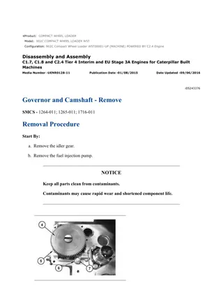
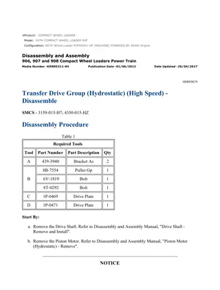
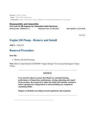
w 1/2(W) Product: COMPACT WHEEL LOADER Model: 907M COMPACT WHEEL LOADER H77 Configuration: 907M Compact Wheel Loader H7700001-UP (MACHINE) POWERED BY C3.3B Engine Disassembly and Assembly C3.3B Tier 4 Final and EU Stage 3B Engines for Caterpillar Built Machines Media Number -UENR3278-07 Publication Date -01/09/2014 Date Updated -11/07/2016 i05223991 Engine Oil Cooler - Remove and Install SMCS - 1378-010 Removal Procedure Note: Refer to Specification UENR3421 "Engine Design" for non-specified engine Torque Values. 1. Refer to Operation and Maintenance Manual, "Cooling System Coolant (ELC) - Change" for the correct draining and filling procedures. Illustration 1 g02788218 2. Remove engine oil filter (3) from engine oil cooler (1). 3. Disconnect hose assemblies (2) and (4). https://127.0.0.1/sisweb/sisweb/techdoc/techdoc_print_page.jsp?returnurl=/sisweb/siswe... 2023/5/6
w 2/2(W) Illustration 2 g02788221 4. Remove center stud (5) and remove engine oil cooler (1) from the locator. 5. Remove the O-ring seal from engine oil cooler (1). Installation Procedure 1. Install engine oil cooler (1) in the reverse order of removal. a. Install the O-ring seal. Position engine oil cooler (1) on the locator on the front housing. Install center stud (5). Tighten center stud (5) to a torque of 40 to 44 N m (29 to 33 lb ft). https://127.0.0.1/sisweb/sisweb/techdoc/techdoc_print_page.jsp?returnurl=/sisweb/siswe... 2023/5/6
w 1/2(W) Product: COMPACT WHEEL LOADER Model: 907M COMPACT WHEEL LOADER H77 Configuration: 907M Compact Wheel Loader H7700001-UP (MACHINE) POWERED BY C3.3B Engine Disassembly and Assembly C3.3B Tier 4 Final and EU Stage 3B Engines for Caterpillar Built Machines Media Number -UENR3278-07 Publication Date -01/09/2014 Date Updated -11/07/2016 i05224010 Engine Oil Relief Valve - Remove and Install SMCS - 1315-010 Removal Procedure Note: Refer to Specification UENR3421 "Engine Design" for non-specified engine Torque Values. Illustration 1 g02788578 Illustration 2 g02788541 https://127.0.0.1/sisweb/sisweb/techdoc/techdoc_print_page.jsp?returnurl=/sisweb/siswe... 2023/5/6
w 2/2(W) Personal injury can result from being struck by parts propelled by a released spring force. Make sure to wear all necessary protective equipment. Follow the recommended procedure and use all recommended tooling to release the spring force. 1. Loosen plug (1). Carefully remove plug (1) from the front housing cover. Note: The spring force will be released when the plug is removed. 2. Remove plug (1), washer (2), spring (3), and plunger (4) from the bore for the relief valve in the front housing cover. Installation Procedure 1. Install engine oil relief valve in the reverse order of removal. a. Install plug (1) and tighten plug (1) to a torque of 69 to 78 N m (51 to 57 lb ft). Note: Ensure that the spring is properly located inside the plunger and the plug. https://127.0.0.1/sisweb/sisweb/techdoc/techdoc_print_page.jsp?returnurl=/sisweb/siswe... 2023/5/6
w 1/4(W) Product: COMPACT WHEEL LOADER Model: 907M COMPACT WHEEL LOADER H77 Configuration: 907M Compact Wheel Loader H7700001-UP (MACHINE) POWERED BY C3.3B Engine Disassembly and Assembly C3.3B Tier 4 Final and EU Stage 3B Engines for Caterpillar Built Machines Media Number -UENR3278-07 Publication Date -01/09/2014 Date Updated -11/07/2016 i05306471 Engine Oil Pump - Remove and Install SMCS - 1304-010 Removal Procedure Start By: a. Remove the front housing. Note: Refer to Specifications, "Engine Design" for non-specified engine torque values. NOTICE Care must be taken to ensure that fluids are contained during performance of inspection, maintenance, testing, adjusting and repair of the product. Be prepared to collect the fluid with suitable containers before opening any compartment or disassembling any component containing fluids. Dispose of all fluids according to local regulations and mandates. https://127.0.0.1/sisweb/sisweb/techdoc/techdoc_print_page.jsp?returnurl=/sisweb/siswe... 2023/5/6
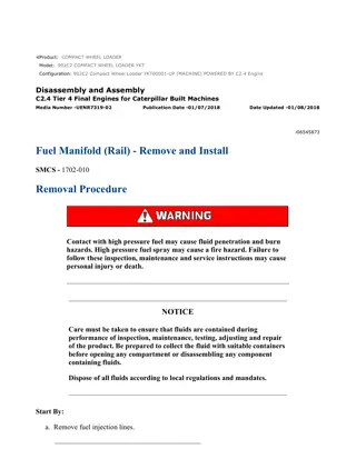
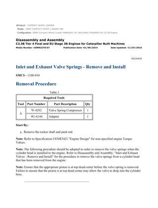
w 2/4(W) Illustration 1 g02788686 1. Remove screws (2) and cover (1). Illustration 2 g02788689 2. Remove inner rotor (4) from outer rotor (3). Installation Procedure Table 1 Required Tools Tool Part Number Part Description Qty A 129-1967 White Grease 1 NOTICE Keep all parts clean from contaminants. Contaminants may cause rapid wear and shortened component life. https://127.0.0.1/sisweb/sisweb/techdoc/techdoc_print_page.jsp?returnurl=/sisweb/siswe... 2023/5/6
w 3/4(W) NOTICE If any part of the engine oil pump is worn or damaged, the complete assembly of the engine oil pump must be replaced. 1. Ensure that all components of the engine oil pump are clean and free from wear and damage. 2. Refer to Specifications, "Engine Oil Pump" for all the engine oil pump allowable clearances. Illustration 3 g02788689 3. Position outer rotor (3) into the pump body. Check the clearance between outer rotor (3) and the pump body. 4. Install inner rotor (4) into outer rotor (3). Check the clearance between the lobes of outer rotor (3) and inner rotor (4). Illustration 4 g02788686 5. Position a strip of Plastigage onto the outer rotor face with Tooling (A). Position cover (1) and install screws (2) and torque. Remove cover (1) and check clearance between the rotor and cover (1). https://127.0.0.1/sisweb/sisweb/techdoc/techdoc_print_page.jsp?returnurl=/sisweb/siswe... 2023/5/6
w 4/4(W) 6. Position cover (1) and install screws (2). Tighten screws (2) to a torque of 8 to 9 N m (70 to 83 lb in). End By: a. Install the front housing. https://127.0.0.1/sisweb/sisweb/techdoc/techdoc_print_page.jsp?returnurl=/sisweb/siswe... 2023/5/6
Suggest: For more complete manuals. Please go to the home page. https://www.ebooklibonline.com If the above button click is invalid. Please download this document first, and then click the above link to download the complete manual. Thank you so much for reading
w 1/2(W) Product: COMPACT WHEEL LOADER Model: 907M COMPACT WHEEL LOADER H77 Configuration: 907M Compact Wheel Loader H7700001-UP (MACHINE) POWERED BY C3.3B Engine Disassembly and Assembly C3.3B Tier 4 Final and EU Stage 3B Engines for Caterpillar Built Machines Media Number -UENR3278-07 Publication Date -01/09/2014 Date Updated -11/07/2016 i05223975 Water Pump - Remove and Install SMCS - 1361-011; 1361-012 Removal Procedure Start By: a. Remove the v-belts. Note: Refer to Specification UENR3421 "Engine Design" for non-specified engine Torque Values. 1. Refer to Operation and Maintenance Manual, "Cooling System Coolant (ELC) - Change" for the correct draining and filling procedures. Illustration 1 g02794283 2. Remove bolts (2) and remove pulley (1). https://127.0.0.1/sisweb/sisweb/techdoc/techdoc_print_page.jsp?returnurl=/sisweb/siswe... 2023/5/6
w 2/2(W) Illustration 2 g02794286 3. Remove bolts (4). 4. Remove water pump (3) and discard the gasket. Install a new gasket upon installation. Installation Procedure 1. Install water pump (3) in the reverse order of removal. https://127.0.0.1/sisweb/sisweb/techdoc/techdoc_print_page.jsp?returnurl=/sisweb/siswe... 2023/5/6
https://www.ebooklibonline.com Hello dear friend! Thank you very much for reading. Enter the link into your browser. The full manual is available for immediate download. https://www.ebooklibonline.com