Caterpillar Cat 977K 977L TRACK LOADER (Prefix 11K) Service Repair Manual Instant Download (11K05051-07762)
Please open the website below to get the complete manualnn//
Download Presentation

Please find below an Image/Link to download the presentation.
The content on the website is provided AS IS for your information and personal use only. It may not be sold, licensed, or shared on other websites without obtaining consent from the author. Download presentation by click this link. If you encounter any issues during the download, it is possible that the publisher has removed the file from their server.
E N D
Presentation Transcript
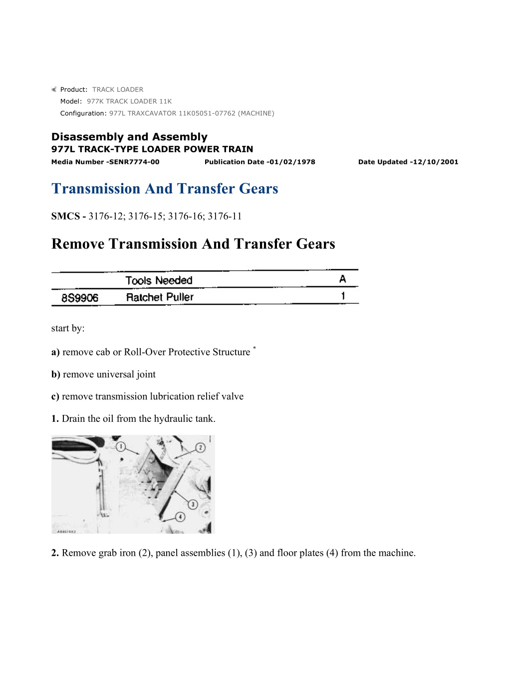
977L TRAXCAVATOR 11K05051-07762 (MACHINE)(UEG0732S - 00) - Document... 1/47 Product: TRACK LOADER Model: 977K TRACK LOADER 11K Configuration: 977L TRAXCAVATOR 11K05051-07762 (MACHINE) Disassembly and Assembly 977L TRACK-TYPE LOADER POWER TRAIN Media Number -SENR7774-00 Publication Date -01/02/1978 Date Updated -12/10/2001 Transmission And Transfer Gears SMCS - 3176-12; 3176-15; 3176-16; 3176-11 Remove Transmission And Transfer Gears start by: a) remove cab or Roll-Over Protective Structure * b) remove universal joint c) remove transmission lubrication relief valve 1. Drain the oil from the hydraulic tank. 2. Remove grab iron (2), panel assemblies (1), (3) and floor plates (4) from the machine. https://127.0.0.1/sisweb/sisweb/techdoc/techdoc_print_page.jsp?returnurl=/sis... 2021/11/7
977L TRAXCAVATOR 11K05051-07762 (MACHINE)(UEG0732S - 00) - Document... 2/47 3. Disconnect the wiring harnesses at connection (6). 4. Remove the bolts that hold horn switch bracket (5) to the frame. Move bracket (5) to the side of the machine. 5. Remove four screws (7) and move cover (8) from the instrument panel. 6. Remove the screws that hold instrument panel lights (11) in cover (8). Remove cover (8) from the machine. 7. Remove the four bolts (9) and move instrument panel (10) to the top of the frame. *This operation is in the OPERATOR'S STATION DISASSEMBLY AND ASSEMBLY section. https://127.0.0.1/sisweb/sisweb/techdoc/techdoc_print_page.jsp?returnurl=/sis... 2021/11/7
977L TRAXCAVATOR 11K05051-07762 (MACHINE)(UEG0732S - 00) - Document... 3/47 8. Remove plate assembly (12) and the two angle assemblies that hold the plate assembly to the frame. 9. Remove parking brake ratchet (16) and spring (15). 10. Remove springs (14) and (18). Remove rod assemblies (13) and (17) from the machine. 11. Remove rod assemblies (19) from the steering clutch hydraulic control and brake pedals. https://127.0.0.1/sisweb/sisweb/techdoc/techdoc_print_page.jsp?returnurl=/sis... 2021/11/7
https://www.ebooklibonline.com Hello dear friend! Thank you very much for reading. Enter the link into your browser. The full manual is available for immediate download. https://www.ebooklibonline.com
977L TRAXCAVATOR 11K05051-07762 (MACHINE)(UEG0732S - 00) - Document... 4/47 12. Remove tube assembly (20) from the machine. 13. Disconnect tube assembly (21) from tube assembly (23). 14. Remove tube assemblies (22) from the machine. 15. Remove pedal and support assembly (24). VIEW FROM UNDER MACHINE 16. Remove tube assemblies (25) and (26) from between the transmission and torque converter. VIEW FROM UNDER MACHINE 17. Remove hose assemblies (27) and (28) from the machine. https://127.0.0.1/sisweb/sisweb/techdoc/techdoc_print_page.jsp?returnurl=/sis... 2021/11/7
977L TRAXCAVATOR 11K05051-07762 (MACHINE)(UEG0732S - 00) - Document... 5/47 18. Disconnect hose assembly (29) from the hydraulic pump. 19. Remove tube assemblies (32) and (33) as a unit. 20. Remove the bolts that hold heater hose clips (30) and (34) in position. 21. Remove transmission oil filter housing (31) from the torque converter housing. 22. Loosen the hose clamp next to the right side of the transmission and remove tube assembly (35) from the hose and hydraulic pump. 23. Fasten a hoist to hydraulic pump (36). Remove the bolts and remove pump (36) from the torque converter housing. The weight of the pump is 75 lb. (34 kg). 24. Remove magnetic screen group (38) from the machine. https://127.0.0.1/sisweb/sisweb/techdoc/techdoc_print_page.jsp?returnurl=/sis... 2021/11/7
977L TRAXCAVATOR 11K05051-07762 (MACHINE)(UEG0732S - 00) - Document... 6/47 25. Disconnect rod assemblies (39) from the transmission. Remove the bolts that hold bracket (37) in position and move the transmission control linkage to the side of the machine. 26. Remove the bolt that holds the tube assembly for magnetic screen group (38) from the left front of the transmission. 27. Disconnect hose assembly (40) from the back of the transmission. 28. Install three 5/8"-11 NC forged eyebolts in the top of the transmission. Fasten a hoist and tool (A) to the transmission. 29. Remove the nuts and lockwashers that hold the transmission and transfer gears to the bevel gear case. 30. Use two 1/2"-13 NC forcing screws to make a separation of the transmission and transfer gears from the bevel gear case. 31. Use tool (A) to make the transmission and transfer gears level and remove the unit from the top of the machine. The weight of the unit is 1050 lb. (473 kg). Install Transmission And Transfer Gears https://127.0.0.1/sisweb/sisweb/techdoc/techdoc_print_page.jsp?returnurl=/sis... 2021/11/7
977L TRAXCAVATOR 11K05051-07762 (MACHINE)(UEG0732S - 00) - Document... 7/47 1. Fasten a hoist and tool (A) to the transmission and transfer gear case with three 5/8"-11 NC forged eyebolts. 2. Make sure the O-ring seal is in position in the transfer gear case assembly and put clean oil in it. 3. Put the transmission and transfer gears in position in the bevel gear case. Make sure the pinion gear engages correctly with the bevel gear. VIEW FROM UNDER MACHINE 4. Install all of nuts (1) and the lockwashers that hold the transfer gear case assembly to the bevel gear case. 5. Connect hose assembly (2) to the transmission. https://127.0.0.1/sisweb/sisweb/techdoc/techdoc_print_page.jsp?returnurl=/sis... 2021/11/7
977L TRAXCAVATOR 11K05051-07762 (MACHINE)(UEG0732S - 00) - Document... 8/47 6. Put bracket (3) and rod assemblies (4) in position. Install the bolts and lockwashers to hold bracket (3). Connect rod assemblies (4) to the transmission. 7. Install the bolt that holds the tube assembly to the left front of the transmission. 8. Install magnetic screen group (5) and tighten the clamps on hose (6). 9. Install the O-ring seal on hydraulic pump (7) and put clean oil on it. Fasten a hoist to pump (7) and put it in position in the torque converter housing. Install the bolts and lockwashers to hold the pump in position. 10. Install the O-ring seal in tube assembly (8) and put clean oil on it. Connect tube assembly (8) to the hydraulic pump and short hose at the right side of the transmission. https://127.0.0.1/sisweb/sisweb/techdoc/techdoc_print_page.jsp?returnurl=/sis... 2021/11/7
977L TRAXCAVATOR 11K05051-07762 (MACHINE)(UEG0732S - 00) - Document... 9/47 11. Put clean oil on the O-ring seals for transmission oil filter housing (9). Install the O-ring seals and filter housing (9) on the torque converter housing. 12. Put clean oil on the O-ring seals for tube assemblies (10) and (12). Install the O-ring seals, tube assembly (10), hose (11) and tube assembly (12). 13. Fasten the clips to the torque converter housing and transmission to hold heater hoses (13) in position. 14. Put clean oil on the O-ring seal and install it in hose assembly (14). Connect hose assembly (14) to the hydraulic pump. VIEW FROM UNDER MACHINE 15. Put clean oil on the O-ring seals and install hose assemblies (15) and (16). https://127.0.0.1/sisweb/sisweb/techdoc/techdoc_print_page.jsp?returnurl=/sis... 2021/11/7
977L TRAXCAVATOR 11K05051-07762 (MACHINE)(UEG0732S - 00) - Docum... 10/47 VIEW FROM UNDER MACHINE 16. Put clean oil on the O-ring seals and install tube assemblies (17) and (18) on the machine. 17. Install pedal and support assembly (19). 18. Put clean oil on the O-ring seals and install tube assemblies (20) and (22). Connect tube assembly (21) to tube assembly (23). 19. Connect rod assemblies (24) and (25) to the foot pedals and steering hydraulic control valve. https://127.0.0.1/sisweb/sisweb/techdoc/techdoc_print_page.jsp?returnurl=/sis... 2021/11/7
977L TRAXCAVATOR 11K05051-07762 (MACHINE)(UEG0732S - 00) - Docum... 11/47 20. Install the two springs (26) to the foot pedals. 21. Connect rod assemblies (27) to the foot pedals and brake actuating mechanisms. 22. Install spring (29) and ratchet (28) for the parking brake. 23. Install plate assembly (30) and the two angle assemblies that hold plate assembly (30) to the machine. 24. Put the wiring harness and instrument panel (32) in position. Install the four bolts and lockwashers to hold instrument panel (32). 25. Install the instrument panel lights in cover (31) and install the cover. https://127.0.0.1/sisweb/sisweb/techdoc/techdoc_print_page.jsp?returnurl=/sis... 2021/11/7
977L TRAXCAVATOR 11K05051-07762 (MACHINE)(UEG0732S - 00) - Docum... 12/47 26. Install the bolts to hold horn switch and bracket (33) in position. 27. Connect wiring harnesses (34) together. 28. Install floor plates (37), grab iron (35) and panel assemblies (36) on each side of the machine. 29. Fill the hydraulic system with oil to the correct level. See LUBRICATION AND MAINTENANCE GUIDE. end by: a) install transmission lubrication relief valve b) install universal joint c) install cab or Roll-Over Protective Structure * *This operation is in the OPERATOR'S STATION DISASSEMBLY AND ASSEMBLY section. Disassemble Transmission And Transfer Gears https://127.0.0.1/sisweb/sisweb/techdoc/techdoc_print_page.jsp?returnurl=/sis... 2021/11/7
977L TRAXCAVATOR 11K05051-07762 (MACHINE)(UEG0732S - 00) - Docum... 13/47 start by: a) remove transmission and transfer gears 1. Put the transmission and transfer gears in a horizontal position on the floor and use tool (A) and blocks for support. 2. Remove cover (1) and the gasket from the transmission case. https://127.0.0.1/sisweb/sisweb/techdoc/techdoc_print_page.jsp?returnurl=/sis... 2021/11/7
977L TRAXCAVATOR 11K05051-07762 (MACHINE)(UEG0732S - 00) - Docum... 14/47 3. Remove the three bolts and washers that hold pressure control valve (2) in position and remove the valve from the transmission case. 4. Remove all of O-ring seals (3) and (4) from the selector valve. 5. Remove sleeve (5) from the transmission case. Remove the O-ring seals from sleeve (5). 6. Remove the three bolts and washers that hold selector valve (6) in position and remove the valve from the transmission case. 7. Remove O-ring seals (8) and sleeves (7) from the transmission. Remove the O-ring seals from the sleeves. NOTE: See DISASSEMBLE TRANSMISSION HYDRAULIC CONTROL VALVES to disassemble the pressure and selector control valves. https://127.0.0.1/sisweb/sisweb/techdoc/techdoc_print_page.jsp?returnurl=/sis... 2021/11/7
977L TRAXCAVATOR 11K05051-07762 (MACHINE)(UEG0732S - 00) - Docum... 15/47 8. Fasten a hoist to the transmission and transfer gears and put the unit in position on tool (B) as shown. Install four 1/2"-13 NC bolts and nuts to hold the unit on tool (B). 9. Remove all of bolts (9) and (10) from the transmission case. 10. Install two 1/2"-13 NC forged eyebolts and fasten a hoist to transmission case (11). Remove case (11) from the transfer gear case. The weight of case (11) is 140 lb. (63 kg). 11. Remove spring (15) from the detent assembly and dowel. 12. Remove the nuts, washers and bolts that hold cam (13) and lever (14) to shaft (12). 13. Pull shaft (12) from the transmission case to remove lever (14) and cam (13). 14. Remove nut (16), the lockwasher and bolt to remove the detent assembly from the transmission case. 15. Remove seal (17) from the transmission case. Use tool group (C) to remove bearings (18) and the plug from the transmission case. https://127.0.0.1/sisweb/sisweb/techdoc/techdoc_print_page.jsp?returnurl=/sis... 2021/11/7
977L TRAXCAVATOR 11K05051-07762 (MACHINE)(UEG0732S - 00) - Docum... 16/47 16. Remove spring (19) from the dowel and detent assembly (21). 17. Remove the nut, washer and bolt that hold cam (20) to the shaft. Remove the shaft from the transmission case to remove cam (20). 18. Remove nut (23), the washer and bolt to remove detent assembly (21). 19. Remove seal (22) and the two bearings from the transmission case. 20. Remove bolts (25) and the locks that hold bearing cage (24). 21. Install two 3/8"-16 NC forged eyebolts in the bearing cage and fasten a hoist as shown. Remove the bearing cage and input shaft as a unit. The weight of the unit is 55 lb. (25 kg). https://127.0.0.1/sisweb/sisweb/techdoc/techdoc_print_page.jsp?returnurl=/sis... 2021/11/7
977L TRAXCAVATOR 11K05051-07762 (MACHINE)(UEG0732S - 00) - Docum... 17/47 22. Remove O-ring seal (26) from cage (24). 23. Remove the bolt, washer and flange (27) from the input shaft. 24. Use tool (D) to remove seal (28) from cage (24). 25. Remove ring (29) and spacer (30) from input shaft (31). 26. Remove the bearing cage from input shaft (31). 27. Remove ring (32) that holds bearing (33) in the cage. https://127.0.0.1/sisweb/sisweb/techdoc/techdoc_print_page.jsp?returnurl=/sis... 2021/11/7
977L TRAXCAVATOR 11K05051-07762 (MACHINE)(UEG0732S - 00) - Docum... 18/47 28. Use tool group (C) to remove bearing (33) from cage (24). The bearing can only be removed from the side of cage (24) that ring (32) was removed. 29. Remove seal rings (34) from cage (24). 30. Remove ring (35) that holds bearing race (36) and gears (37) on the shaft. 31. Remove the two gears and bearing race from input shaft (31) with tooling (E). TYPICAL EXAMPLE 32. Use a soft faced hammer to remove bearing cage (38) from the input shaft. https://127.0.0.1/sisweb/sisweb/techdoc/techdoc_print_page.jsp?returnurl=/sis... 2021/11/7
977L TRAXCAVATOR 11K05051-07762 (MACHINE)(UEG0732S - 00) - Docum... 19/47 33. Remove ring (39) and bearing (40) from cage (38). NOTE: Put identification on each of the clutch housings for correct installation and alignment at assembly. If the clutch plates and disc assemblies are to be used again keep these parts together and do not mix them. 34. Remove bolts (41) that hold the clutch housings together. 35. Install tooling (F) to hold No. 1 piston in No. 1 clutch housing (42). 36. Install two 1/2"-13 NC forged eyebolts in No. 1 clutch housing (42). Fasten a hoist and remove the piston and housing as a unit. The weight of the unit is 55 lb. (25 kg). 37. Remove springs (43) from the No. 2 clutch housing. https://127.0.0.1/sisweb/sisweb/techdoc/techdoc_print_page.jsp?returnurl=/sis... 2021/11/7
977L TRAXCAVATOR 11K05051-07762 (MACHINE)(UEG0732S - 00) - Docum... 20/47 38. Remove piston (44) from clutch housing (42). Remove the seal rings from the piston and housing. 39. Remove the three disc assemblies (45) and two plates (46). 40. Remove ring gear (47). 41. Install two 3/8"-16 NC forged eyebolts in No. 1 carrier (48) and fasten a hoist. Remove carrier (48). The weight of the carrier is 65 lb. (29 kg). 42. Remove bolts (50), the locks and plates (51) to remove gear (49) from No. 1 carrier (48). https://127.0.0.1/sisweb/sisweb/techdoc/techdoc_print_page.jsp?returnurl=/sis... 2021/11/7
977L TRAXCAVATOR 11K05051-07762 (MACHINE)(UEG0732S - 00) - Docum... 21/47 43. Remove shafts (55), gears (53) and washers (52) from No. 1 carrier (48). There is a washer on each side of the gears. Remove bearings (54) from the gears. NOTICE When shafts (55) and (57) are removed, balls (56) and (62) can fall out of the shafts. Take care not to loose balls (56) and (62). 44. Remove shafts (57), gears (58), washers (60) and tubes (61) from No. 1 carrier (48). There is a washer on each side of the gears. Remove bearings (59) from the gears. 45. Use tool group (C) to remove bearing (63) from No. 1 carrier (48). https://127.0.0.1/sisweb/sisweb/techdoc/techdoc_print_page.jsp?returnurl=/sis... 2021/11/7
977L TRAXCAVATOR 11K05051-07762 (MACHINE)(UEG0732S - 00) - Docum... 22/47 46. Remove plate (64) from the No. 2 clutch housing. If necessary, remove dowels (65) from plate (64). 47. Remove gear (67), the three disc assemblies (66), the two plates (69) and pins (68) from the No. 2 clutch housing. 48. Install two 1/2"-13 NC forged eyebolts in No. 2 clutch housing (71) and fasten a hoist. Remove housing (71). The weight of the housing is 50 lb. (23 kg). 49. Remove piston (70) from No. 2 clutch housing (71). Remove the seal rings from the piston and housing. 50. Remove springs (72) from the No. 3 clutch housing. 51. Remove two disc assemblies (73) and plate (74) from the No. 3 clutch housing. https://127.0.0.1/sisweb/sisweb/techdoc/techdoc_print_page.jsp?returnurl=/sis... 2021/11/7
977L TRAXCAVATOR 11K05051-07762 (MACHINE)(UEG0732S - 00) - Docum... 23/47 52. Remove bolts (77), the locks and plates (76) to remove gear (75) from the No. 3 clutch housing. 53. Install two 1/2"-13 NC forged eyebolts in No. 3 clutch housing (78) and fasten a hoist. Remove clutch housing (78). The weight of the clutch housing is 55 lb. (25 kg). 54. Remove springs (81) from the No. 4 and 5 clutch housing. 55. Remove piston (79) from clutch housing (78). Remove the seal rings from the piston and housing. 56. If necessary, remove dowels (80) from No. 3 clutch housing (78). 57. Remove the two disc assemblies (82) and plate (83). 58. Remove gear (84) and pins (85) from the No. 4 and 5 clutch housing. 59. Install tooling (F) to hold the No. 4 and 5 clutch pistons in position. https://127.0.0.1/sisweb/sisweb/techdoc/techdoc_print_page.jsp?returnurl=/sis... 2021/11/7
977L TRAXCAVATOR 11K05051-07762 (MACHINE)(UEG0732S - 00) - Docum... 24/47 60. Install two 1/2"-13 NC forged eyebolts in the No. 4 and 5 clutch housing (86) and fasten a hoist. Remove clutch housing (86) and the pistons as a unit. The weight of the unit is 75 lb. (34 kg). 61. Remove springs (87) from the plate. 62. Remove tooling (F) and the pistons from clutch housing (86). Remove the seal rings from the pistons and clutch housing. 63. Remove the two disc assemblies (88) and plate (89) from the plate. 64. Remove gear (90) from the plate. 65. Remove the three bolts (91) and washers from inside No. 2 carrier (92). Remove the three bolts (93) and locks from No. 2 carrier (92). https://127.0.0.1/sisweb/sisweb/techdoc/techdoc_print_page.jsp?returnurl=/sis... 2021/11/7
977L TRAXCAVATOR 11K05051-07762 (MACHINE)(UEG0732S - 00) - Docum... 25/47 66. Install two 3/8"-16 NC forged eyebolts in No. 2 carrier (92) and fasten a hoist. Remove the No. 2 carrier. The weight of the carrier is 50 lb. (23 kg). 67. Remove shafts (97), gears (95), gears (94) and washers (96) from No. 2 carrier (92). There is a washer on each side of the gears. Remove the bearings from the gears. NOTICE When shafts (97) and (99) are removed, balls (98) and (101) can fall out of the shafts. Take care not to loose balls (98) and (101). 68. Remove shafts (99), gears (102) and washers (100) from No. 2 carrier (92). There is a washer on each side of the gears. Remove bearings (103) from gears (102). https://127.0.0.1/sisweb/sisweb/techdoc/techdoc_print_page.jsp?returnurl=/sis... 2021/11/7
Suggest: For more complete manuals. Please go to the home page. https://www.ebooklibonline.com If the above button click is invalid. Please download this document first, and then click the above link to download the complete manual. Thank you so much for reading
977L TRAXCAVATOR 11K05051-07762 (MACHINE)(UEG0732S - 00) - Docum... 26/47 69. Use two 1/2"-13 NC forcing screws to remove plate (104) from the output transfer gears. 70. If necessary, remove dowels (105) from plate (104). 71. Remove the output transfer gears from tool (A) and put them on blocks with the input shaft down. The weight of the transfer gears is approximately 150 lb. (68 kg). 72. Remove bolts (106) and the locks to remove cage (107). 73. Remove the plug from cage (107) and use a 6-40 screw to remove dowel (109) from the cage. 74. Remove bearing (108) from cage (107) with tool group (C). https://127.0.0.1/sisweb/sisweb/techdoc/techdoc_print_page.jsp?returnurl=/sis... 2021/11/7
977L TRAXCAVATOR 11K05051-07762 (MACHINE)(UEG0732S - 00) - Docum... 27/47 75. Remove the ring that holds input shaft (114) to gear (110) and remove the shaft. 76. Remove bolts (112) and the locks that hold case (113) and cover (111) together. 77. Install three 3/8"-16 NC forcing screws and tighten them evenly to remove cover (111) from case (113). 78. Remove plug (117) and use a 6-40 screw to remove the dowel that holds bearing race (115). NOTE: Remove the plug and use a 6-40 screw to remove the dowel that holds bearing race (116), if so equipped. 79. Remove bearing races (115) and (116) from cover (111). 80. Remove gear (119) and pinion (118) from case (113). https://127.0.0.1/sisweb/sisweb/techdoc/techdoc_print_page.jsp?returnurl=/sis... 2021/11/7
https://www.ebooklibonline.com Hello dear friend! Thank you very much for reading. Enter the link into your browser. The full manual is available for immediate download. https://www.ebooklibonline.com


