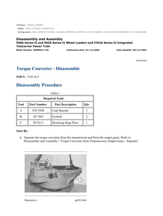
Caterpillar Cat 962G Wheel Loader (Prefix 4PW) Service Repair Manual Instant Download
Please open the website below to get the complete manualnn//
Download Presentation

Please find below an Image/Link to download the presentation.
The content on the website is provided AS IS for your information and personal use only. It may not be sold, licensed, or shared on other websites without obtaining consent from the author. Download presentation by click this link. If you encounter any issues during the download, it is possible that the publisher has removed the file from their server.
E N D
Presentation Transcript
Service Repair Manual Models 962G WheelLoader
962G Wheel Loader 4PW00001-UP (MACHINE) POWERED BY 3126 Engine(SEBP... 1/11 Shutdown SIS Previous Screen Product: WHEEL LOADER Model: 962G WHEEL LOADER 4PW Configuration: 962G Wheel Loader 4PW00001-UP (MACHINE) POWERED BY 3126 Engine Disassembly and Assembly 950G and 962G Wheel Loaders and IT62G Integrated Toolcarrier Power Train Media Number -SENR1381-10 Publication Date -01/10/2007 Date Updated -25/10/2007 i00734834 Output Transfer Gears - Disassemble SMCS - 3075-015 Disassembly Procedure Table 1 Required Tools Tool Part Number Part Description Qty 1P-0520 Driver Group 1 A 1P-2322 Puller Assembly 1 8B-7556 Adapter 2 8B-7548 Push-Puller 1 B 8B-7560 Step Plate 1 8H-0684 Ratchet Box Wrench 1 C 8B-7551 Bearing Puller Attachment 1 Start By: A. Separate the output transfer gears from the transmission planetary group. Refer to Disassembly and Assembly, "Transmission from Output Transfer Gears - Separate". Note: Cleanliness is an important factor. Before disassembly, the exterior of the case should be thoroughly cleaned in order to prevent dirt and debris from entering the internal mechanism. During disassembly, all parts should be thoroughly cleaned in cleaning fluid. Then allow the parts to air dry. Wiping cloths or rags should not be used to dry the parts. Lint may be deposited on the parts. This may cause later trouble. https://127.0.0.1/sisweb/sisweb/techdoc/techdoc_print_page.jsp?returnurl=/sis... 2020/3/28
962G Wheel Loader 4PW00001-UP (MACHINE) POWERED BY 3126 Engine(SEBP... 2/11 Illustration 1 g00332214 1. Remove speed sensors (1) . Illustration 2 g00332215 Note: Keep the shim pack together for assembly purposes. 2. Remove bolts (2). Use two forcing screws of a suitable size to remove bearing cage assembly (3) and the shim pack. 3. Remove the lip seal, the O-ring seal and the bearing cup from bearing cage assembly (3) . https://127.0.0.1/sisweb/sisweb/techdoc/techdoc_print_page.jsp?returnurl=/sis... 2020/3/28
https://www.ebooklibonline.com Hello dear friend! Thank you very much for reading. Enter the link into your browser. The full manual is available for immediate download. https://www.ebooklibonline.com
962G Wheel Loader 4PW00001-UP (MACHINE) POWERED BY 3126 Engine(SEBP... 3/11 Illustration 3 g00332234 4. Put the output transfer gear group on wood blocks, as shown. The weight of the output transfer gear group is 231 kg (510 lb). 5. Remove lifting eye bracket (4) . Illustration 4 g00332254 6. Remove bolts (5) that hold bearing cage assembly (6) to the housing. https://127.0.0.1/sisweb/sisweb/techdoc/techdoc_print_page.jsp?returnurl=/sis... 2020/3/28
962G Wheel Loader 4PW00001-UP (MACHINE) POWERED BY 3126 Engine(SEBP... 4/11 Illustration 5 g00332255 7. Use two 3/8" - 16 NC forcing screws (7) to remove bearing cage assembly (6) from the housing. Note: Keep the shim pack together for assembly purposes. 8. Remove shim pack (8) . Illustration 6 g00332256 9. Remove bearing cup (9) and O-ring seal (10) from bearing cage assembly (6) . Illustration 7 g00332257 10. Fasten a suitable lifting sling and a hoist to input transfer gear (11). Use a hoist to remove input transfer gear (11). The weight of the input transfer gear is 23 kg (50 lb). https://127.0.0.1/sisweb/sisweb/techdoc/techdoc_print_page.jsp?returnurl=/sis... 2020/3/28
962G Wheel Loader 4PW00001-UP (MACHINE) POWERED BY 3126 Engine(SEBP... 5/11 Illustration 8 g00332258 11. Use Tooling (A) to remove bearing cone (12). Repeat this step for the opposite side of the input transfer gear. Illustration 9 g00332259 12. Remove bearing cup (13) from the output transfer gear housing. Illustration 10 g00332537 https://127.0.0.1/sisweb/sisweb/techdoc/techdoc_print_page.jsp?returnurl=/sis... 2020/3/28
962G Wheel Loader 4PW00001-UP (MACHINE) POWERED BY 3126 Engine(SEBP... 6/11 13. Remove spacer (14) from the output shaft. Illustration 11 g00332260 14. Put the output transfer gear group in a vertical position, as shown. 15. Remove bolt (15) and yoke retainer (16) from the output shaft. Illustration 12 g00332261 16. Remove yoke assembly (17) from the output shaft. https://127.0.0.1/sisweb/sisweb/techdoc/techdoc_print_page.jsp?returnurl=/sis... 2020/3/28
962G Wheel Loader 4PW00001-UP (MACHINE) POWERED BY 3126 Engine(SEBP... 7/11 Illustration 13 g00332262 17. Remove bolts (18) . Illustration 14 g00332263 18. Use two 3/8" - 16 NC forcing screws to remove bearing cage assembly (19) from the output transfer gear housing. Illustration 15 g00332264 https://127.0.0.1/sisweb/sisweb/techdoc/techdoc_print_page.jsp?returnurl=/sis... 2020/3/28
962G Wheel Loader 4PW00001-UP (MACHINE) POWERED BY 3126 Engine(SEBP... 8/11 19. Remove bearing cage assembly (19) . Illustration 16 g00332266 20. Remove lip seal (20) from the bearing cage assembly. Illustration 17 g00332268 21. Remove bearing cup (21) and O-ring seal (22) from the bearing cage assembly. https://127.0.0.1/sisweb/sisweb/techdoc/techdoc_print_page.jsp?returnurl=/sis... 2020/3/28
962G Wheel Loader 4PW00001-UP (MACHINE) POWERED BY 3126 Engine(SEBP... 9/11 Illustration 18 g00332269 22. Use a hoist and a suitable lifting sling to hold output transfer gear (23) in position. 23. Use Tooling (B) to push output shaft (25) from transfer gear (23) and from bearing cone (24) . 24. Remove transfer gear (23) from output shaft (25) . Illustration 19 g00332271 25. Remove output shaft (25) and bearing cone (24) from the output transfer gear housing. Illustration 20 g00332272 Note: The output shaft is free to fall when the bearing cone is removed. 26. Use a press and Tooling (C) to push the output shaft from bearing cone (24) . https://127.0.0.1/sisweb/sisweb/techdoc/techdoc_print_page.jsp?returnurl=/sis... 2020/3/28
962G Wheel Loader 4PW00001-UP (MACHINE) POWERED BY 3126 Engine(SE... 10/11 Illustration 21 g00332274 27. Remove transfer gear (23) from the output transfer gear housing. Illustration 22 g00332275 28. Remove bolts (26) and cover (27) from the output transfer gear housing. Illustration 23 g00333661 29. Remove O-ring seal (28) from cover (27) . https://127.0.0.1/sisweb/sisweb/techdoc/techdoc_print_page.jsp?returnurl=/sis... 2020/3/28
962G Wheel Loader 4PW00001-UP (MACHINE) POWERED BY 3126 Engine(SE... 11/11 Illustration 24 g00332278 30. Remove suction screen (30) and screen tube assembly (29) . Illustration 25 g00332280 31. Separate suction screen (30) from screen tube assembly (29) . 32. Remove magnet assembly (31) from screen tube assembly (29) . Copyright 1993 - 2020 Caterpillar Inc. Sat Mar 28 16:50:36 UTC+0800 2020 All Rights Reserved. Private Network For SIS Licensees. https://127.0.0.1/sisweb/sisweb/techdoc/techdoc_print_page.jsp?returnurl=/sis... 2020/3/28
962G Wheel Loader 4PW00001-UP (MACHINE) POWERED BY 3126 Engine(SEBP... 1/11 Shutdown SIS Previous Screen Product: WHEEL LOADER Model: 962G WHEEL LOADER 4PW Configuration: 962G Wheel Loader 4PW00001-UP (MACHINE) POWERED BY 3126 Engine Disassembly and Assembly 950G and 962G Wheel Loaders and IT62G Integrated Toolcarrier Power Train Media Number -SENR1381-10 Publication Date -01/10/2007 Date Updated -25/10/2007 i06502801 Output Transfer Gears - Assemble SMCS - 3075-016 Assembly Procedure Table 1 Required Tools Tool Part Number Part Description Qty A 1P-0520 Driver Group 1 B 8T-5096 Dial Indicator Gp 1 Note: Cleanliness is an important factor. Before assembly, all parts should be thoroughly cleaned in cleaning fluid. Allow the parts to air dry. Wiping cloths or rags should not be used to dry parts. Lint may be deposited on the parts. This may cause later trouble. Inspect all parts. If any parts are worn or damaged, use new parts for replacement. Illustration 1 g00332280 https://127.0.0.1/sisweb/sisweb/techdoc/techdoc_print_page.jsp?returnurl=/sis... 2020/3/28
962G Wheel Loader 4PW00001-UP (MACHINE) POWERED BY 3126 Engine(SEBP... 2/11 1. Make sure that magnet assembly (31) is in position on the screen tube assembly (29). 2. Install screen tube assembly (29) in suction screen (30). Illustration 2 g00333658 3. Install screen tube assembly (29) and suction screen (30) in the output transfer gear housing. Illustration 3 g00333661 4. Install O-ring seal (28) on cover (27). Apply clean oil on O-ring seal (28). Illustration 4 g00332275 https://127.0.0.1/sisweb/sisweb/techdoc/techdoc_print_page.jsp?returnurl=/sis... 2020/3/28
962G Wheel Loader 4PW00001-UP (MACHINE) POWERED BY 3126 Engine(SEBP... 3/11 5. Install cover (27) and bolts (26). Illustration 5 g00334038 6. Install output transfer gear (23) in the output transfer gear housing, as shown. Illustration 6 g00334039 7. Heat bearing cone (24) to a maximum temperature of 135 C (275 F). Install bearing cone (24) on output shaft (25). Make sure that the bearing cone contacts the mating surface. 8. Lift transfer gear (23) in order to align the bore with the output shaft. Install output shaft (25). 9. Heat bearing cone (24) to a maximum temperature of 135 C (275 F). Install bearing cone (24) on the opposite end of output shaft (25). Make sure that the bearing cone contacts the mating surface. https://127.0.0.1/sisweb/sisweb/techdoc/techdoc_print_page.jsp?returnurl=/sis... 2020/3/28
962G Wheel Loader 4PW00001-UP (MACHINE) POWERED BY 3126 Engine(SEBP... 4/11 Illustration 7 g00332268 10. Lower the temperature of bearing cup (21). Install bearing cup (21) in bearing cage assembly (19). 11. Install O-ring seal (22) on bearing cage assembly (19). Illustration 8 g00334040 12. Apply 7M-7260 Liquid Gasket to the seal bore. Allow the liquid gasket to dry. Use Tooling (A) to install the lip seal in bearing cage assembly (19). Illustration 9 g00334041 https://127.0.0.1/sisweb/sisweb/techdoc/techdoc_print_page.jsp?returnurl=/sis... 2020/3/28
962G Wheel Loader 4PW00001-UP (MACHINE) POWERED BY 3126 Engine(SEBP... 5/11 Illustration 10 g00332262 13. Apply clean transmission oil to O-ring seal (22). Install bearing cage assembly (19). Install bolts (18). The torque for bolts (18) is 60 12 N m (44 9 lb ft). 14. Repeat Steps 10 through 12 in order to assemble bearing cage assembly (3). Illustration 11 g00332537 15. Install spacer (14) on the output shaft. https://127.0.0.1/sisweb/sisweb/techdoc/techdoc_print_page.jsp?returnurl=/sis... 2020/3/28
962G Wheel Loader 4PW00001-UP (MACHINE) POWERED BY 3126 Engine(SEBP... 6/11 Illustration 12 g00334158 Note: The bearing axis must be vertical for correct end play adjustment. 16. Use a 0.038 mm (0.0015 inch) shim or a standard feeler gauge to ensure that the bearing cups and the bearing cones are seated in the housing. Note: Do not install the O-ring seal or the shims at this time. 17. Use two cage bolts (2) in order to install bearing cage assembly (3). The cage bolts are separated by 180 degrees. 18. Tighten two cage bolts (2) to a torque of 1.7 N m (15 lb in). 19. Turn output shaft (25) for at least three revolutions in order to seat the bearings. 20. Tighten two cage bolts (2) to a torque of 3.4 N m (30 lb in). 21. Turn output shaft (25) for at least three revolutions in order to seat the bearings. https://127.0.0.1/sisweb/sisweb/techdoc/techdoc_print_page.jsp?returnurl=/sis... 2020/3/28
962G Wheel Loader 4PW00001-UP (MACHINE) POWERED BY 3126 Engine(SEBP... 7/11 22. Tighten two cage bolts (2) again to a torque of 3.4 N m (30 lb in). 23. Measure the gap between the case and bearing cage assembly (3) at two cage bolts (2). Perform the measurement between the outside diameter of the flange and the cage bolts. 24. Average the two measurements from Step 23. Add 0.23 mm (0.009 inch) to the average. This result is the required thickness of the shims. 25. Remove bearing cage assembly (3). Install the O-ring seal on bearing cage assembly (3). Apply clean transmission oil to the O-ring seal. Install bearing cage assembly (3) with the required shims from Step 24. Install cage bolts (2). The torque for cage bolts (2) is 60 12 N m (44 9 lb ft). 26. Use Tooling (B) to measure the bearing end play. If the bearing end play is less than 0.05 mm (0.002 inch), add shims. If the bearing end play is more than .11 mm (0.004 inch), remove shims. Illustration 13 g00332261 27. Install yoke assembly (17). Illustration 14 g00332260 28. Install yoke retainer (16) and bolt (15) on the output shaft. The torque for bolt (15) is 240 40 N m (177 30 lb ft). https://127.0.0.1/sisweb/sisweb/techdoc/techdoc_print_page.jsp?returnurl=/sis... 2020/3/28
962G Wheel Loader 4PW00001-UP (MACHINE) POWERED BY 3126 Engine(SEBP... 8/11 Illustration 15 g00332259 29. Lower the temperature of bearing cup (13). Install bearing cup (13) in the output transfer gear housing. Illustration 16 g00334223 30. Heat bearing cones (12) to a maximum temperature of 135 C (275 F). Install one bearing cone (12) on each side of input transfer gear (11). Illustration 17 g00334227 31. Install input transfer gear (11), as shown. https://127.0.0.1/sisweb/sisweb/techdoc/techdoc_print_page.jsp?returnurl=/sis... 2020/3/28
962G Wheel Loader 4PW00001-UP (MACHINE) POWERED BY 3126 Engine(SEBP... 9/11 Illustration 18 g00332256 32. Lower the temperature of bearing cup (9). Install bearing cup (9) in bearing cage assembly (6). Do not install O-ring seal (10) at this time. Illustration 19 g00334230 https://127.0.0.1/sisweb/sisweb/techdoc/techdoc_print_page.jsp?returnurl=/sis... 2020/3/28
962G Wheel Loader 4PW00001-UP (MACHINE) POWERED BY 3126 Engine(SE... 10/11 Note: The bearing axis must be vertical for correct end play adjustment. 33. Use a 0.038 mm (0.0015 inch) shim or a standard feeler gauge to ensure that the bearing cups and the bearing cones are seated in the housing. Note: Do not install the O-ring seal or the shims at this time. 34. Use two cage bolts (5) in order to install bearing cage assembly (6). The cage bolts are separated by 180 degrees. 35. Tighten two cage bolts (5) to a torque of 1.7 N m (15 lb in). 36. Turn input transfer gear (11) for at least three revolutions in order to seat the bearings. 37. Tighten two cage bolts (5) to a torque of 3.4 N m (30 lb in). 38. Turn input transfer gear (11) for at least three revolutions in order to seat the bearings. 39. Tighten two cage bolts (5) again to a torque of 3.4 N m (30 lb in). 40. Measure the gap between the case and bearing cage assembly (6) at two cage bolts (5). Perform the measurement between the outside diameter of the flange and the cage bolts. 41. Average the two measurements from Step 40. Add 0.23 mm (0.009 inch) to the average. This result is the required thickness of the shims. 42. Remove bearing cage assembly (6). Install the O-ring seal on bearing cage assembly (5). Apply clean transmission oil to the O-ring seal. Install bearing cage assembly (6) with the required shims from Step 41. Install cage bolts (5). The torque for cage bolts (5) is 60 12 N m (44 9 lb ft). 43. Use Tooling (B) to measure the bearing end play. If the bearing end play is less than 0.05 mm (0.002 inch), add shims. If the bearing end play is more than 0.15 mm (0.006 inch), remove shims. Illustration 20 g00332234 44. Install lifting eye bracket (4). https://127.0.0.1/sisweb/sisweb/techdoc/techdoc_print_page.jsp?returnurl=/sis... 2020/3/28
962G Wheel Loader 4PW00001-UP (MACHINE) POWERED BY 3126 Engine(SE... 11/11 Illustration 21 g00332214 45. Use the following procedure to install speed sensors (1): a. Align the gear tooth with the center of the hole for the transmission speed sensor. b. Apply 5P-3413 Pipe Sealant to the threads of the sensor. Install the sensor. Screw the sensor inward until the sensor contacts the gear tooth. c. Back off the sensor by 1/2 turn. Tighten the adjustment locknut. The torque for the adjustment locknut is 25 5 N m (18 4 lb ft). Note: Do not allow the sensor to turn as the adjustment locknut is tightened. End By: a. Connect the output transfer gears to the transmission planetary group. Refer to Disassembly and Assembly, "Transmission to Output Transfer Gears - Connect". Copyright 1993 - 2020 Caterpillar Inc. Sat Mar 28 16:51:35 UTC+0800 2020 All Rights Reserved. Private Network For SIS Licensees. https://127.0.0.1/sisweb/sisweb/techdoc/techdoc_print_page.jsp?returnurl=/sis... 2020/3/28
962G Wheel Loader 4PW00001-UP (MACHINE) POWERED BY 3126 Engine(SEBP... 1/2 Shutdown SIS Previous Screen Product: WHEEL LOADER Model: 962G WHEEL LOADER 4PW Configuration: 962G Wheel Loader 4PW00001-UP (MACHINE) POWERED BY 3126 Engine Disassembly and Assembly 950G and 962G Wheel Loaders and IT62G Integrated Toolcarrier Power Train Media Number -SENR1381-10 Publication Date -01/10/2007 Date Updated -25/10/2007 i00732414 Transmission to Output Transfer Gears - Connect SMCS - 3002-077 Connection Procedure Table 1 Required Tools Tool Part Number Part Description Qty A 138-7575 Link Bracket 1 Illustration 1 g00336158 1. Use a hoist to install the transmission planetary group on the output transfer gear case. The weight of the transmission planetary group is 545 kg (1200 lb). https://127.0.0.1/sisweb/sisweb/techdoc/techdoc_print_page.jsp?returnurl=/sis... 2020/3/28
962G Wheel Loader 4PW00001-UP (MACHINE) POWERED BY 3126 Engine(SEBP... 2/2 Illustration 2 g00326944 2. Install O-ring seal (3) . 3. Remove Tooling (A) from the transmission planetary group. Illustration 3 g00326943 4. Install drain tube assembly (2) and bolts (1) . End By: Connect the torque converter to the transmission. Refer to Disassembly and Assembly, "Torque Converter to Transmission, Output Transfer Gears - Connect". Copyright 1993 - 2020 Caterpillar Inc. Sat Mar 28 16:52:34 UTC+0800 2020 All Rights Reserved. Private Network For SIS Licensees. https://127.0.0.1/sisweb/sisweb/techdoc/techdoc_print_page.jsp?returnurl=/sis... 2020/3/28
962G Wheel Loader 4PW00001-UP (MACHINE) POWERED BY 3126 Engine(SEBP... 1/5 Shutdown SIS Previous Screen Product: WHEEL LOADER Model: 962G WHEEL LOADER 4PW Configuration: 962G Wheel Loader 4PW00001-UP (MACHINE) POWERED BY 3126 Engine Disassembly and Assembly 950G and 962G Wheel Loaders and IT62G Integrated Toolcarrier Power Train Media Number -SENR1381-10 Publication Date -01/10/2007 Date Updated -25/10/2007 i01624201 Torque Converter to Transmission, Output Transfer Gears - Connect SMCS - 3003-077 Connection Procedure Table 1 Required Tools Tool Part Number Part Description Qty A 138-7575 Link Bracket 3 Note: Check the condition of all parts. If any parts are worn or damaged, use new parts for replacement. Illustration 1 g00335880 https://127.0.0.1/sisweb/sisweb/techdoc/techdoc_print_page.jsp?returnurl=/sis... 2020/3/28
Suggest: If the above button click is invalid. Please download this document first, and then click the above link to download the complete manual. Thank you so much for reading
962G Wheel Loader 4PW00001-UP (MACHINE) POWERED BY 3126 Engine(SEBP... 2/5 1. Install the O-ring seal on the transmission housing. Apply clean power train oil on the O- ring seal. 2. Use a suitable hoist in order to install torque converter assembly (12) on the transmission planetary group. The weight of the torque converter assembly is 159 kg (350 lb). Illustration 2 g00317628 3. Install bolts (14) that hold torque converter assembly (12) to the transmission planetary group. The torque for bolts (14) is 120 20 N m (90 15 lb ft). Illustration 3 g00335879 4. Put the torque converter, the transmission and the output gears in a horizontal position on wood blocks. 5. Remove bolts (13) that hold torque converter assembly (12) to the transmission planetary group. The torque for bolts (13) is 120 20 N m (90 15 lb ft). https://127.0.0.1/sisweb/sisweb/techdoc/techdoc_print_page.jsp?returnurl=/sis... 2020/3/28
https://www.ebooklibonline.com Hello dear friend! Thank you very much for reading. Enter the link into your browser. The full manual is available for immediate download. https://www.ebooklibonline.com

