Caterpillar Cat 930G Wheel Loader (Prefix TFW) Service Repair Manual Instant Download (TFW00001 and up)
Please open the website below to get the complete manualnn//
Download Presentation

Please find below an Image/Link to download the presentation.
The content on the website is provided AS IS for your information and personal use only. It may not be sold, licensed, or shared on other websites without obtaining consent from the author. Download presentation by click this link. If you encounter any issues during the download, it is possible that the publisher has removed the file from their server.
E N D
Presentation Transcript
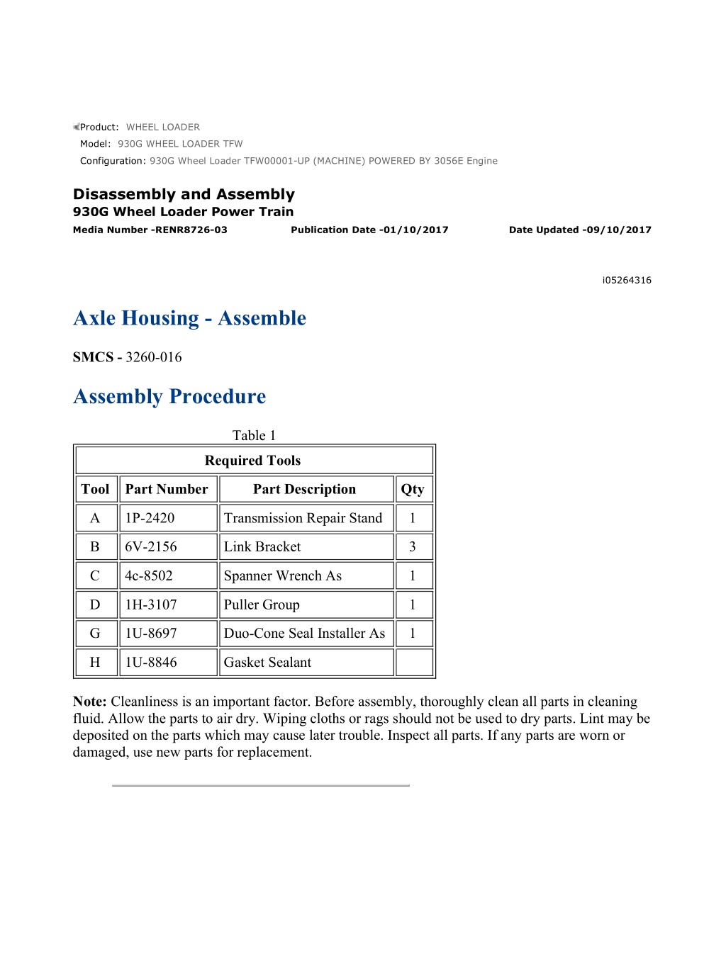
930G Wheel Loader TFW00001-UP (MACHINE) POWERED BY 3056E Engine(SE... 1/8 Product: WHEEL LOADER Model: 930G WHEEL LOADER TFW Configuration: 930G Wheel Loader TFW00001-UP (MACHINE) POWERED BY 3056E Engine Disassembly and Assembly 930G Wheel Loader Power Train Media Number -RENR8726-03 Publication Date -01/10/2017 Date Updated -09/10/2017 i05264316 Axle Housing - Assemble SMCS - 3260-016 Assembly Procedure Table 1 Required Tools Tool Part Number Part Description Qty A 1P-2420 Transmission Repair Stand 1 B 6V-2156 Link Bracket 3 C 4c-8502 Spanner Wrench As 1 D 1H-3107 Puller Group 1 G 1U-8697 Duo-Cone Seal Installer As 1 H 1U-8846 Gasket Sealant Note: Cleanliness is an important factor. Before assembly, thoroughly clean all parts in cleaning fluid. Allow the parts to air dry. Wiping cloths or rags should not be used to dry parts. Lint may be deposited on the parts which may cause later trouble. Inspect all parts. If any parts are worn or damaged, use new parts for replacement. https://127.0.0.1/sisweb/sisweb/techdoc/techdoc_print_page.jsp?returnurl=/sis... 2022/5/19
930G Wheel Loader TFW00001-UP (MACHINE) POWERED BY 3056E Engine(SE... 2/8 Illustration 1 g00671305 1. Use Tooling (G) in order to install seal (19). Refer to Disassembly and Assembly, "Duo- Cone Conventional Seals - Install" for the proper procedure. Note: Lubricate the bearing with the lubricant that is being used. 2. Raise the temperature of bearing cone (20). 3. Install bearing cone (20). Illustration 2 g00671344 4. Lower the temperature of bearing cup (18). 5. Install bearing cup (18). Use Tooling (G) in order to install seal (17). Refer to Disassembly and Assembly, "Duo-Cone Conventional Seals - Install" for the proper procedure. https://127.0.0.1/sisweb/sisweb/techdoc/techdoc_print_page.jsp?returnurl=/sis... 2022/5/19
930G Wheel Loader TFW00001-UP (MACHINE) POWERED BY 3056E Engine(SE... 3/8 Illustration 3 g01132120 6. Lower the temperature of bearing cup (15). 7. Install bearing cup (15). 8. Lower the temperature of ring gear (16) and install ring gear (16). Install pins (14) and peen the housing in order to retain pins (14). Illustration 4 g00671536 9. Use a suitable lifting device and Tooling (B) in order to install axle housing (13) onto the axle shaft. The weight of axle housing (13) is approximately 88 kg (195 lb). Use Tooling (A) in order to support axle housing (13). 10. Raise the temperature of bearing cone (12). 11. Install bearing cone (12). 12. Lubricate bearing cone (12) with the lubricant that is being sealed. https://127.0.0.1/sisweb/sisweb/techdoc/techdoc_print_page.jsp?returnurl=/sis... 2022/5/19
https://www.ebooklibonline.com Hello dear friend! Thank you very much for reading. Enter the link into your browser. The full manual is available for immediate download. https://www.ebooklibonline.com
930G Wheel Loader TFW00001-UP (MACHINE) POWERED BY 3056E Engine(SE... 4/8 Illustration 5 g00670405 Illustration 6 g00670407 Note: Lubricate nut (11) with the lubricant that is being sealed. 13. Install nut (11). Use Tooling (C) in order to tighten nut (11). Leave slight bearing end play. Illustration 7 g00671551 14. Use Tooling (A) in order to support the axle shaft. Install Tooling (D), as shown. Install a bolt in the center of Tooling (D). Use a torque wrench in order to rotate the axle housing and check the rolling torque (SD). This is the amount of seal drag. https://127.0.0.1/sisweb/sisweb/techdoc/techdoc_print_page.jsp?returnurl=/sis... 2022/5/19
930G Wheel Loader TFW00001-UP (MACHINE) POWERED BY 3056E Engine(SE... 5/8 15. Use Tooling (C) in order to tighten nut (11). Check the rolling torque (RT). This is the total rolling torque. Subtract the seal drag torque (SD) from the total rolling torque (RT). This is the rolling torque of the axle bearings. Tighten nut (11) until a rolling torque of the axle bearings is 4 N m to 9 N m (35 lb in to 80 lb in). The rolling torque for used axle bearings should be 2 N m to 4.5 N m (18 lb in to 40 lb in). Illustration 8 g00670404 16. Install bearing (10) in gear (8). Illustration 9 g00671595 17. Install gear (8) and washers (9). 18. Install shaft (7). https://127.0.0.1/sisweb/sisweb/techdoc/techdoc_print_page.jsp?returnurl=/sis... 2022/5/19
930G Wheel Loader TFW00001-UP (MACHINE) POWERED BY 3056E Engine(SE... 6/8 Illustration 10 g01131675 Note: The openings of pins (6) must be 180 degrees away from each other. The openings of pins (6) must be parallel to the carrier deck. Refer to illustration 10. 19. Install pins (6). 20. Deform pin holes slightly with a chisel. 21. Repeat Steps 16 through 19 for the remaining gear assemblies. Illustration 11 g00670400 https://127.0.0.1/sisweb/sisweb/techdoc/techdoc_print_page.jsp?returnurl=/sis... 2022/5/19
930G Wheel Loader TFW00001-UP (MACHINE) POWERED BY 3056E Engine(SE... 7/8 22. Use Tooling (B) and a suitable lifting device in order to install carrier assembly (5). The weight of carrier assembly (5) is approximately 28 kg (62 lb). Illustration 12 g00670395 23. Install retaining ring (4). 24. Use a suitable lifting device in order to remove the axle housing from Tooling (A). The weight of the axle housing is approximately 147 kg (325 lb). Illustration 13 g01132124 25. Clean the mating surfaces of the axle housing and apply a continuous bead of Tooling (H). https://127.0.0.1/sisweb/sisweb/techdoc/techdoc_print_page.jsp?returnurl=/sis... 2022/5/19
930G Wheel Loader TFW00001-UP (MACHINE) POWERED BY 3056E Engine(SE... 8/8 Illustration 14 g00663942 26. Use a suitable lifting device in order to install axle housing (1). The weight of axle housing assembly (1) is approximately 147 kg (325 lb). Install bolts (2). 27. Fill the axle housing with oil. Refer to Operation and Maintenance Manual, "Lubrication Viscosities and Refill Capacities". End By: a. Install the axle trunnion (front and rear) on the oscillating axle housing. Refer to Disassembly and Assembly, "Axle Trunnion (Front and Rear) - Remove and Install". b. Install the fixed axle housing. Refer to Disassembly and Assembly, "Fixed Axle Housing - Install". https://127.0.0.1/sisweb/sisweb/techdoc/techdoc_print_page.jsp?returnurl=/sis... 2022/5/19
930G Wheel Loader TFW00001-UP (MACHINE) POWERED BY 3056E Engine(SE... 1/6 Product: WHEEL LOADER Model: 930G WHEEL LOADER TFW Configuration: 930G Wheel Loader TFW00001-UP (MACHINE) POWERED BY 3056E Engine Disassembly and Assembly 930G Wheel Loader Power Train Media Number -RENR8726-03 Publication Date -01/10/2017 Date Updated -09/10/2017 i02248047 Brake and Planetary - Remove and Install SMCS - 4011-010; 4251-010; 4255-010 Removal Procedure Table 1 Required Tools Tool Part Number Part Description Qty A 1P-2420 Transmission Repair Stand 1 Start By: a. Remove the axle trunnions. Refer to Disassembly and Assembly, "Trunnion Support (Oscillating Axle, Front) - Remove and Install" and Disassembly and Assembly, "Trunnion Support (Oscillating Axle, Rear) - Remove and Install". b. Remove the fixed axle. Refer to Disassembly and Assembly, "Fixed Axle (Front) - Remove". https://127.0.0.1/sisweb/sisweb/techdoc/techdoc_print_page.jsp?returnurl=/sis... 2022/5/19
930G Wheel Loader TFW00001-UP (MACHINE) POWERED BY 3056E Engine(SE... 2/6 Illustration 1 g01131954 Personal injury can result from being struck by parts propelled by a released spring force. Make sure to wear all necessary protective equipment. Follow the recommended procedure and use all recommended tooling to release the spring force. 1. Position axle housing assembly (1) and housing (2) as a unit onto Tooling (A). The weight of axle housing assembly (1) and housing (2) as a unit is approximately 590 kg (1300 lb). 2. Attach a suitable lifting device onto axle housing assembly (1). Remove bolts (3). Remove axle housing assembly (1). The weight of axle housing assembly (1) is approximately 159 kg (350 lb). https://127.0.0.1/sisweb/sisweb/techdoc/techdoc_print_page.jsp?returnurl=/sis... 2022/5/19
930G Wheel Loader TFW00001-UP (MACHINE) POWERED BY 3056E Engine(SE... 3/6 Illustration 2 g01131921 3. Remove gear (4), plate (5), and springs (6). Illustration 3 g01131922 4. Remove disc (7) and piston (8). https://127.0.0.1/sisweb/sisweb/techdoc/techdoc_print_page.jsp?returnurl=/sis... 2022/5/19
930G Wheel Loader TFW00001-UP (MACHINE) POWERED BY 3056E Engine(SE... 4/6 Illustration 4 g01131923 5. Remove seals (9) and (10). Installation Procedure Illustration 5 g01131923 1. Lubricate seals (9) and (10) with the lubricant that is being sealed. Install seals (9) and (10). https://127.0.0.1/sisweb/sisweb/techdoc/techdoc_print_page.jsp?returnurl=/sis... 2022/5/19
930G Wheel Loader TFW00001-UP (MACHINE) POWERED BY 3056E Engine(SE... 5/6 Illustration 6 g01131922 2. Install piston (8) and disc (7). Illustration 7 g01131921 3. Install springs (6), plate (5), and gear (4). https://127.0.0.1/sisweb/sisweb/techdoc/techdoc_print_page.jsp?returnurl=/sis... 2022/5/19
930G Wheel Loader TFW00001-UP (MACHINE) POWERED BY 3056E Engine(SE... 6/6 Illustration 8 g01131954 Improper assembly of parts that are spring loaded can cause bodily injury. To prevent possible injury, follow the established assembly procedure and wear protective equipment. 4. Attach a suitable lifting device onto axle housing assembly (1). Position axle housing assembly (1) onto housing (2). The weight of axle housing assembly (1) is approximately 159 kg (350 lb). 5. Install bolts (3). Tighten bolts (3) to a torque of 300 40 N m (221 30 lb ft). 6. Remove axle housing assembly (1) and housing (2) as a unit from Tooling (A). The weight of axle housing assembly (1) and housing (2) as a unit is approximately 590 kg (1300 lb). End By: a. Install the fixed axle. Refer to Disassembly and Assembly, "Fixed Axle (Front) - Install". b. Install the axle trunnions. Refer to Disassembly and Assembly, "Trunnion Support (Oscillating Axle, Front) - Remove and Install" and Disassembly and Assembly, "Trunnion Support (Oscillating Axle, Rear) - Remove and Install". https://127.0.0.1/sisweb/sisweb/techdoc/techdoc_print_page.jsp?returnurl=/sis... 2022/5/19
930G Wheel Loader TFW00001-UP (MACHINE) POWERED BY 3056E Engine(SE... 1/6 Product: WHEEL LOADER Model: 930G WHEEL LOADER TFW Configuration: 930G Wheel Loader TFW00001-UP (MACHINE) POWERED BY 3056E Engine Disassembly and Assembly 930G Wheel Loader Power Train Media Number -RENR8726-03 Publication Date -01/10/2017 Date Updated -09/10/2017 i01740530 Differential and Bevel Gear - Remove SMCS - 3256-011; 3258-011 Removal Procedure Table 1 Required Tools Tool Part Number Part Description Qty 1U-6400 Puller Group 1 A 0S-2389 Spacer 1 Start By: a. Remove the service brakes. Refer to Disassembly and Assembly, "Service Brakes - Remove and Install". NOTICE Care must be taken to ensure that fluids are contained during performance of inspection, maintenance, testing, adjusting, and repair of the product. Be prepared to collect the fluid with suitable containers before opening any compartment or disassembling any component containing fluids. Refer to Special Publication, NENG2500, "Dealer Service Tool Catalog" for tools and supplies suitable to collect and contain fluids on Cat products. Dispose of all fluids according to local regulations and mandates. https://127.0.0.1/sisweb/sisweb/techdoc/techdoc_print_page.jsp?returnurl=/sis... 2022/5/19
930G Wheel Loader TFW00001-UP (MACHINE) POWERED BY 3056E Engine(SE... 2/6 Hot oil and hot components can cause personal injury. Do not allow hot oil or hot components to contact skin. At operating temperature, the engine coolant is hot and under pressure. Steam can cause personal injury. Check the coolant level only after the engine has been stopped and the cooling system pressure cap is cool enough to touch with your bare hand. Remove the cooling system pressure cap slowly to relieve pressure. Cooling system conditioner contains alkali. Avoid contact with the skin and eyes to prevent personal injury. Note: Cleanliness is an important factor. Before the disassembly procedure, the exterior of the component should be thoroughly cleaned. This will help to prevent dirt from entering the internal mechanism. Illustration 1 g00665873 Note: Plug all hose assemblies. This helps to keep contaminates from entering the system. 1. Remove hose assemblies (1). https://127.0.0.1/sisweb/sisweb/techdoc/techdoc_print_page.jsp?returnurl=/sis... 2022/5/19
930G Wheel Loader TFW00001-UP (MACHINE) POWERED BY 3056E Engine(SE... 3/6 Illustration 2 g00665875 2. Use a suitable lifting device in order to support intermediate housing (3). Remove bolts (2). Remove intermediate housing (3). The weight of intermediate housing (3) is approximately 34 kg (75 lb). Illustration 3 g00665876 3. Remove the bolt and lock (4). Remove nut (5). Illustration 4 g00665877 4. Remove bearing cone (6). https://127.0.0.1/sisweb/sisweb/techdoc/techdoc_print_page.jsp?returnurl=/sis... 2022/5/19
930G Wheel Loader TFW00001-UP (MACHINE) POWERED BY 3056E Engine(SE... 4/6 Illustration 5 g00665878 5. Use a suitable lifting device in order to support the pinion housing assembly. Remove bolts (7). The weight of pinion housing assembly is approximately 29 kg (65 lb). Illustration 6 g00894847 6. Remove shims (8) and O-ring seal (9). Illustration 7 g00893553 7. Use a suitable lifting device in order to remove differential assembly (10). The weight of differential assembly (10) is approximately 27 kg (60 lb). https://127.0.0.1/sisweb/sisweb/techdoc/techdoc_print_page.jsp?returnurl=/sis... 2022/5/19
930G Wheel Loader TFW00001-UP (MACHINE) POWERED BY 3056E Engine(SE... 5/6 Illustration 8 g00893554 8. Use Tooling (A) in order to remove bearing cone (11). Illustration 9 g00893555 9. Use Tooling (A) in order to remove bearing cone (12). Illustration 10 g00893556 10. Remove bolts (11) and gear (12). https://127.0.0.1/sisweb/sisweb/techdoc/techdoc_print_page.jsp?returnurl=/sis... 2022/5/19
Suggest: For more complete manuals. Please go to the home page. https://www.ebooklibonline.com If the above button click is invalid. Please download this document first, and then click the above link to download the complete manual. Thank you so much for reading
930G Wheel Loader TFW00001-UP (MACHINE) POWERED BY 3056E Engine(SE... 1/4 Product: WHEEL LOADER Model: 930G WHEEL LOADER TFW Configuration: 930G Wheel Loader TFW00001-UP (MACHINE) POWERED BY 3056E Engine Disassembly and Assembly 930G Wheel Loader Power Train Media Number -RENR8726-03 Publication Date -01/10/2017 Date Updated -09/10/2017 i01252992 Differential Pinion (Front) - Disassemble SMCS - 3254-015-FR; 3269-015-FR Disassembly Procedure Start By: a. Remove the differential and bevel gear. Refer to Disassembly and Assembly, "Differential and Bevel Gear - Remove". Note: Cleanliness is an important factor. Before the disassembly procedure, the exterior of the component should be thoroughly cleaned. This will help to prevent dirt from entering the internal mechanism. Illustration 1 g00667621 1. Remove the bolt and retainer (1). https://127.0.0.1/sisweb/sisweb/techdoc/techdoc_print_page.jsp?returnurl=/sis... 2022/5/19
930G Wheel Loader TFW00001-UP (MACHINE) POWERED BY 3056E Engine(SE... 2/4 Illustration 2 g00667623 2. Remove shim pack (2), seal (3), and yoke assembly (4). Illustration 3 g00667624 3. Remove six bolts (5) and retainer (6). Illustration 4 g00667626 4. Remove seal (7). https://127.0.0.1/sisweb/sisweb/techdoc/techdoc_print_page.jsp?returnurl=/sis... 2022/5/19
https://www.ebooklibonline.com Hello dear friend! Thank you very much for reading. Enter the link into your browser. The full manual is available for immediate download. https://www.ebooklibonline.com

