Caterpillar Cat 928F WHEEL LOADER (Prefix 8AK) Service Repair Manual Instant Download (8AK00001-00699)
Please open the website below to get the complete manualnn//
Download Presentation

Please find below an Image/Link to download the presentation.
The content on the website is provided AS IS for your information and personal use only. It may not be sold, licensed, or shared on other websites without obtaining consent from the author. Download presentation by click this link. If you encounter any issues during the download, it is possible that the publisher has removed the file from their server.
E N D
Presentation Transcript
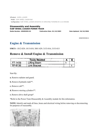
w 1/14(W) Product: WHEEL LOADER Model: 928F WHEEL LOADER 8AK Configuration: 928F WHEEL LOADER 8AK00001-00699 (MACHINE) POWERED BY 3116 ENGINE Disassembly and Assembly 928F WHEEL LOADER POWER TRAIN Media Number -SENR5995-02 Publication Date -01/10/2003 Date Updated -26/10/2004 SENR59950013 Engine & Transmission SMCS - 1012-029; 1013-010; 3001-029; 3153-015; 3153-016 Remove & Install Engine & Transmission Start By: a. Remove radiator and guard. b. Remove hydraulic tank**. c. Remove cab**. d. Remove steering cylinders**. e. Remove drive shaft group*. *Refer to the Power Train Disassembly & Assembly module for this information. NOTE: Identify and mark all lines, hoses and electrical wiring before removing or disconnecting for purposes of reassembly. https://127.0.0.1/sisweb/sisweb/techdoc/techdoc_print_page.jsp?returnurl=/sisweb/sisw... 2022/7/26
w 2/14(W) 1. Remove condenser line (2). 2. Disconnect plug connect (1). 3. Disconnect wire (3) on the solenoid. 4. Disconnect two quick connects (4). 5. Remove two fuel lines (5). 6. Remove two bolts, washers and clips (6) and reposition cable (7). 7. Loosen two clamps (8) and remove the heater lines. 8. Disconnect two spade connectors (9). 9. Remove two bolts and washers (10) and bracket (11). https://127.0.0.1/sisweb/sisweb/techdoc/techdoc_print_page.jsp?returnurl=/sisweb/sisw... 2022/7/26
w 3/14(W) 10. Disconnect quick connect (12) and remove air dryer (13). 11. Disconnect two ground wires (14). 12. Disconnect quick connect (15). 13. Disconnect all wires (16) from the alternator. 14. Disconnect all wires (17) from the starter and solenoid. 15. Disconnect plug connector (18) and spade connector (19). 16. Remove hydraulic line (20). 17. Disconnect quick connect (21). 18. Reposition wiring harness (22). https://127.0.0.1/sisweb/sisweb/techdoc/techdoc_print_page.jsp?returnurl=/sisweb/sisw... 2022/7/26
https://www.ebooklibonline.com Hello dear friend! Thank you very much for reading. Enter the link into your browser. The full manual is available for immediate download. https://www.ebooklibonline.com
w 4/14(W) 19. Disconnect quick connect (23). 20. Disconnect six plugs (24) and reposition wire harness (25). 21. Disconnect quick connect (26) on lower right side of transmission. 22. Remove two bolts, washers and clips (27) holding parking brake (28) to the frame assembly. 23. Remove hydraulic line (29). https://127.0.0.1/sisweb/sisweb/techdoc/techdoc_print_page.jsp?returnurl=/sisweb/sisw... 2022/7/26
w 5/14(W) 24. Attach tool (A) to engine and transmission and a suitable lifting device. 25. Remove two mounting bolts and washers (30) holding the engine to the frame. 26. Remove eight bolts and washers (31) from brackets (32). 27. Remove two mounting bolts and washers (33) from two brackets (32). 28. Remove the engine and transmission as shown. The weight of the engine and transmission is 1362 kg (3000 lb). NOTE: Install in the reverse order. End By: a. install drive shaft* b. install steering valve and diverter valve* c. install steering cylinders** d. install radiator and guard e. install hydraulic tank** f. install cab** https://127.0.0.1/sisweb/sisweb/techdoc/techdoc_print_page.jsp?returnurl=/sisweb/sisw... 2022/7/26
w 6/14(W) *Refer to the Power Train Disassembly & Assembly module for this information. **Refer to the Machine Systems Disassembly & Assembly module for this information. Separate & Connect Engine From Transmission Start By: a. remove engine & transmission 1. Support transmission and engine using tooling (A) and wood blocks as shown. 2. Disconnect all wire clips and connectors. 3. Attach suitable lifting device to the transmission, remove bolts and washers (1) and separate transmission from engine. NOTE: Connect engine & transmisison in the reverse order. End By: a. install engine & transmission Separation & Connection of Torque Converter From Transmission https://127.0.0.1/sisweb/sisweb/techdoc/techdoc_print_page.jsp?returnurl=/sisweb/sisw... 2022/7/26
w 7/14(W) Start By: a. remove transmission 1. Thoroughly clean the outside of the transmission prior to disassembly. 2. Drain the transmission fluid into a suitable container. 3. Mark all parts and components for assembly purposes. 4. Install tool (A), chains and a suitable lifting device to transmission (1) as shown. The weight of the transmission is 700 kg (1545 lb). 5. Move the transmission to a clean safe work area and install on Tool (B) as shown. 6. Install tooling (C), chains and a suitable lifting device to transmission cover (2) as shown. NOTE: Use a bubble level to get the cover as level as possible. https://127.0.0.1/sisweb/sisweb/techdoc/techdoc_print_page.jsp?returnurl=/sisweb/sisw... 2022/7/26
w 8/14(W) 7. Remove twenty seven bolts (3). 8. Slowly and carefully lift the transmission cover straight up far enough to clear input shaft (4). The weight of the transmission cover is 200 kg (440 lb). NOTE: Install in the reverse order. NOTE: Use 6V6640 Gasket Maker on mating surfaces of the torque converter and the transmission. 9. Tighten twenty seven bolts (3) to the torque of 55 10 N m (40 7 lb ft). Disassemble Transmission Pump 1. Remove two bolts (1) and cover (2). 2. Remove seven bolts (3). Check O-ring seal (4) for damage or wear and replace if necessary. https://127.0.0.1/sisweb/sisweb/techdoc/techdoc_print_page.jsp?returnurl=/sisweb/sisw... 2022/7/26
w 9/14(W) 3. Install two forcing screws as shown. 4. Use tool (A), chains and a suitable lifting device to remove gear pump group (5). 5. Remove six bolts (6). 6. Remove shaft (7). 7. Use tool (B) to remove retaining ring (8). https://127.0.0.1/sisweb/sisweb/techdoc/techdoc_print_page.jsp?returnurl=/sisweb/sisw... 2022/7/26
w 10/14(W) 8. Remove gear (9) and ball bearing (10) as a unit. 9. Use a suitable press to remove ball bearing (10) from gear (9). 10. Remove five bolts (11). NOTE: Only one of these bolts marked (X) has a washer. 11. Turn gear pump group (5) over and remove one bolt (12). 12. Separate pump cover assembly (13) from gear pump group (5). 13. If necessary, remove two bushings (14). 14. Check O-ring seal (15) for damage or wear and replace if necessary. https://127.0.0.1/sisweb/sisweb/techdoc/techdoc_print_page.jsp?returnurl=/sisweb/sisw... 2022/7/26
w 11/14(W) 15. Remove two oil pump gears (16). Mark these gears and their location for assembly purposes. 16. Check the condition of the two dowels (17) and replace if necessary. 17. Check the condition of the two dowels (18) and replace if necessary. 18. If necessary, remove two bushings (19). Assemble Transmission Pump 1. If removed, install two bushings (19). https://127.0.0.1/sisweb/sisweb/techdoc/techdoc_print_page.jsp?returnurl=/sisweb/sisw... 2022/7/26
w 12/14(W) 2. Install two oil pump gears (16). 3. Check the condition of two dowels (17) and replace if necessary. 4. Check the condition of two dowels (18) and replace if necessary. 5. If removed, install two bushings (14). 6. Check O-ring seal (15) for damage or wear and replace if necessary. 7. Turn gear pump group (5) over and install one bolt (12). 8. Connect pump cover assembly (13) to gear pump group (5). 9. Install five bolts (11). NOTE: Only one of these bolts marked (X) has a washer. https://127.0.0.1/sisweb/sisweb/techdoc/techdoc_print_page.jsp?returnurl=/sisweb/sisw... 2022/7/26
w 13/14(W) 10. Heat bearing (10) to 135 C (275 F) and install in gear (9). 11. Install gear (9) and bearing (10) as a unit. 12. Use tool (B) to install retaining ring (186). 13. Install shaft (7). https://127.0.0.1/sisweb/sisweb/techdoc/techdoc_print_page.jsp?returnurl=/sisweb/sisw... 2022/7/26
w 14/14(W) 14. Install six bolts (6). 15. Use tool (A), chains and a suitable lifting device to install gear pump group (5). 16. Install seven bolts (3). Check O-ring seal (4) for damage or wear and replace if necessary. 17. Install two bolts (1) and cover (2). https://127.0.0.1/sisweb/sisweb/techdoc/techdoc_print_page.jsp?returnurl=/sisweb/sisw... 2022/7/26
w 1/9(W) Product: WHEEL LOADER Model: 928F WHEEL LOADER 8AK Configuration: 928F WHEEL LOADER 8AK00001-00699 (MACHINE) POWERED BY 3116 ENGINE Disassembly and Assembly 928F WHEEL LOADER POWER TRAIN Media Number -SENR5995-02 Publication Date -01/10/2003 Date Updated -26/10/2004 SENR59950014 Torque Converter SMCS - 3101-015; 3101-016 Disassemble Torque Converter Start By: a. remove engine, transmission and torque converter b. separation of engine from transmission and torque converter c. separation of transmission from torque converter 1. Install tool (A) as shown. 2. Remove six bolts (1). 3. Lift transmission cover (2) straight up and off the torque converter. The weight of the transmission cover if 150 kg (330 lb). https://127.0.0.1/sisweb/sisweb/techdoc/techdoc_print_page.jsp?returnurl=/sisweb/sisw... 2022/7/26
w 2/9(W) 4. Install tool (A) as shown. 5. Remove eighteen bolts (2) and washers. 6. Install two forcing screws as shown. 7. Separate drive gear (3) and stator carrier (4) from rotating housing (5). 8. Remove six socket head bolts (6). 9. Remove two clamp plates (7). 10. Use tool (B) to remove retaining ring (8). https://127.0.0.1/sisweb/sisweb/techdoc/techdoc_print_page.jsp?returnurl=/sisweb/sisw... 2022/7/26
w 3/9(W) 11. Carefully tap stator carrier (4) from converter impeller (9). 12. Check seal ring (11) for damage or wear and replace if necessary. 13. Remove twelve bolts (12). 14. Remove drive gear (3) from converter impeller (9). 15. Use a suitable press to remove ball bearing (13) from converter impeller (9). 16. Use tool (B) to remove retaining ring (14). https://127.0.0.1/sisweb/sisweb/techdoc/techdoc_print_page.jsp?returnurl=/sisweb/sisw... 2022/7/26
w 4/9(W) 17. Lift converter turbine (15) from rotating housing (5). 18. Remove rear bearing lock (16). 19. Remove end cover (17). 20. Turn the rotating housing over and use a soft hammer to tap splined hub and ball bearing (18) out of the housing. https://127.0.0.1/sisweb/sisweb/techdoc/techdoc_print_page.jsp?returnurl=/sisweb/sisw... 2022/7/26
w 5/9(W) 21. Use tool (B) to remove snap ring (19) from splined hub (18). 22. If necessary, remove ball bearing (20) from splined hub (18). 23. Check the condition of locating ring (21) on the outside diameter of ball bearing (20) and replace if necessary. 24. Check oil damn or "D" ring (22) for damage or wear and replace if necessary. Assemble Torque Converter 1. Check oil damn or "D" ring (22) for damage or wear and replace if necessary. 2. Use tool (B) to install snap ring (19) to splined hub (18). 3. If removed, install bearing (20) to splined hub (18). 4. Check the condition of locating ring (21) on the outside diameter of bearing (20) and replace if necessary. https://127.0.0.1/sisweb/sisweb/techdoc/techdoc_print_page.jsp?returnurl=/sisweb/sisw... 2022/7/26
w 6/9(W) 5. Turn the rotating housing over and assemble splined hub and bearing (18) to the housing. 6. Install end cover (17). 7. Install rear bearing lock (16). 8. Assemble converter turbine (15) to rotating housing (5). 9. Use tool (B) to install retaining ring (14). https://127.0.0.1/sisweb/sisweb/techdoc/techdoc_print_page.jsp?returnurl=/sisweb/sisw... 2022/7/26
w 7/9(W) 10. Heat bearing (13) to 135 C (275 F) and assemble to impeller (9). 11. Install drive gear (3) to impeller (9). 12. Install twelve bolts (12) and tighten to the torque of 30 5 N m (22 4 lb ft). 13. Check seal ring (11) for damage or wear and replace if necessary. 14. If removed, install six spring pins (10). 15. Carefully install stator carrier (4) to impeller (9). https://127.0.0.1/sisweb/sisweb/techdoc/techdoc_print_page.jsp?returnurl=/sisweb/sisw... 2022/7/26
Suggest: For more complete manuals. Please go to the home page. https://www.ebooklibonline.com If the above button click is invalid. Please download this document first, and then click the above link to download the complete manual. Thank you so much for reading
w 8/9(W) 16. Install two clamp plates (7). 17. Use tool (B) to install retaining ring (8). 18. Install six socket head bolts (6) and tighten to the torque of 30 5 N m (22 4 lb ft). 19. Assemble drive gear (3) and stator carrier (4) to rotating housing (5). 20. Install tool (A) as shown. 21. Install eighteen bolts (2) and the washers and tighten to a torque of 30 5 N m (22 4 lb ft). https://127.0.0.1/sisweb/sisweb/techdoc/techdoc_print_page.jsp?returnurl=/sisweb/sisw... 2022/7/26
w 9/9(W) 22. Install tool (A) as shown. 23. Use M10 Guide Bolts when lowering transmission cover (2) straight down on the torque converter. The weight of the transmission cover is 150 kg (330 lb). 24. Install six bolts (1) tighten to a torque of 55 10 N m (40 7 lb ft). End By: a. connection of transmission from torque converter b. connection of engine from transmission and torque converter c. install engine, transmission and torque converter https://127.0.0.1/sisweb/sisweb/techdoc/techdoc_print_page.jsp?returnurl=/sisweb/sisw... 2022/7/26
https://www.ebooklibonline.com Hello dear friend! Thank you very much for reading. Enter the link into your browser. The full manual is available for immediate download. https://www.ebooklibonline.com

