Caterpillar Cat 914G Compact Wheel Loader (Prefix PDF) Service Repair Manual Instant Download (PDF00001 and up)
Please open the website below to get the complete manualnn//
Download Presentation

Please find below an Image/Link to download the presentation.
The content on the website is provided AS IS for your information and personal use only. It may not be sold, licensed, or shared on other websites without obtaining consent from the author. Download presentation by click this link. If you encounter any issues during the download, it is possible that the publisher has removed the file from their server.
E N D
Presentation Transcript
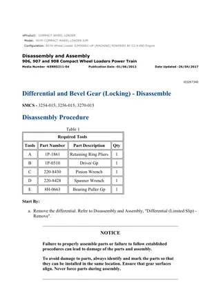
w 1/12(W) Product: COMPACT WHEEL LOADER Model: 914G COMPACT WHEEL LOADER PDF Configuration: 914G Wheel Loader PDF00001-UP (MACHINE) POWERED BY 3054C Engine Disassembly and Assembly 914G and 914G2 Compact Wheel Loaders and IT14G and IT14G2 Integrated Toolcarriers Power Train Media Number -RENR7767-05 Publication Date -01/05/2017 Date Updated -19/05/2017 i02090019 Differential - Disassemble SMCS - 3258-015 Disassembly Procedure Table 1 Required Tools Tool Part Number Part Description Qty 1U-5750 Engine Repair Stand 1 A 1U-7558 Mounting Adapter Gp 2 8B-7554 Bearing Cup Puller 1 B 6V-7887 Legs 2 5P-2958 Step Plate 1 C 6V-2176 Link Bracket 1 5F-7544 Bearing Cup Puller 1 5P-7341 Legs 2 D 9S-9154 Step Plate 1 5P-4750 Screw 1 Start By: A. Remove the parking brake. Refer to Disassembly and Assembly, "Parking Brake - Disassemble". B. Remove the brakes. Refer to Disassembly and Assembly, "Brake and Planetary - Disassemble". https://127.0.0.1/sisweb/sisweb/techdoc/techdoc_print_page.jsp?returnurl=/sisweb/siswe... 2023/3/9
w 2/12(W) C. Remove the axle. Refer to Disassembly and Assembly, "Brake and Planetary - Disassemble". Note: The front differential and the rear differential are identical. The parking brake assembly and the pinion housing are unique to the front differential. Note: Cleanliness is an important factor. Before the disassembly procedure, the exterior of the component should be thoroughly cleaned. This will help to prevent dirt from entering the internal mechanism. NOTICE Care must be taken to ensure that fluids are contained during performance of inspection, maintenance, testing, adjusting and repair of the product. Be prepared to collect the fluid with suitable containers before opening any compartment or disassembling any component containing fluids. Refer to Special Publication, NENG2500, "Caterpillar Tools and Shop Products Guide" for tools and supplies suitable to collect and contain fluids on Caterpillar products. Dispose of all fluids according to local regulations and mandates. Illustration 1 g00683575 1. Use a suitable lifting device in order to attach differential (1) to Tooling (A). The weight of differential (1) is approximately 226.7 kg (500 lb). https://127.0.0.1/sisweb/sisweb/techdoc/techdoc_print_page.jsp?returnurl=/sisweb/siswe... 2023/3/9
w 3/12(W) Illustration 2 g00683096 2. Remove bolts (2) and the washers that secure pinion housing (3) to differential housing (1) . Illustration 3 g00683097 3. Use a suitable lifting device to support pinion housing (3) . 4. Install forcing screws (4) in pinion housing (3) . Illustration 4 g00683099 https://127.0.0.1/sisweb/sisweb/techdoc/techdoc_print_page.jsp?returnurl=/sisweb/siswe... 2023/3/9
https://www.ebooklibonline.com Hello dear friend! Thank you very much for reading. Enter the link into your browser. The full manual is available for immediate download. https://www.ebooklibonline.com
w 4/12(W) 5. Remove pinion housing (3) from differential housing (1). The weight of pinion housing (3) is approximately 29.4 kg (65 lb). 6. Remove shims (5) . Illustration 5 g00683102 7. Remove O-ring (6) . Illustration 6 g00683104 https://127.0.0.1/sisweb/sisweb/techdoc/techdoc_print_page.jsp?returnurl=/sisweb/siswe... 2023/3/9
w 5/12(W) Illustration 7 g00683105 8. Use a press to separate bevel pinion shaft (7) from pinion housing (3) . 9. Remove bearing (8) from pinion shaft (7) . Illustration 8 g00717120 10. Remove bearing race (9) from the pinion housing. Illustration 9 g00683167 11. Use Tooling (B) to remove bearing (10) from pinion housing (3) . 12. Repeat Step 11 for the opposite side. https://127.0.0.1/sisweb/sisweb/techdoc/techdoc_print_page.jsp?returnurl=/sisweb/siswe... 2023/3/9
w 6/12(W) Illustration 10 g00683107 Illustration 11 g00683108 13. Attach Tooling (C) and a suitable lifting device to intermediate differential housing (12). Remove screws (11). Remove intermediate differential housing (12). The weight of intermediate differential housing (12) is approximately 34.0 kg (75 lb). Illustration 12 g00683109 https://127.0.0.1/sisweb/sisweb/techdoc/techdoc_print_page.jsp?returnurl=/sisweb/siswe... 2023/3/9
w 7/12(W) 14. Remove bolt (13), lock (14), and adjustment spanner nut (15) from intermediate differential housing (12) . Illustration 13 g00683111 15. Remove bearing race (16) from the intermediate differential housing (12) . Illustration 14 g00683112 (S/N: 7ZM1-5998ZM1-4999WM1-12981WN1-898) 16. Remove breather (17) and brake bleeder (18) from intermediate differential housing (12) . Note: Breather (17) will be replaced by a bushing and a fitting in machines that are effective with serial numbers (S/N: 7ZM600-UP8ZM500-UP9WM1299-UP1WN899-UP). https://127.0.0.1/sisweb/sisweb/techdoc/techdoc_print_page.jsp?returnurl=/sisweb/siswe... 2023/3/9
w 8/12(W) Illustration 15 g00683113 17. Use a suitable lifting device in order to remove bevel gear assembly (19) from the differential housing. The weight of bevel gear assembly (19) is approximately 27.2 kg (60 lb). Illustration 16 g00683114 18. Remove bearing race (20) from the differential housing. Illustration 17 g00683115 https://127.0.0.1/sisweb/sisweb/techdoc/techdoc_print_page.jsp?returnurl=/sisweb/siswe... 2023/3/9
w 9/12(W) 19. Remove bolts (21) from the bevel gear housing. Illustration 18 g00683118 20. Use a press to separate bevel gear (22) from the differential case. Illustration 19 g00683120 21. Remove thrust washer (25) and gear (24) from differential case (23) . https://127.0.0.1/sisweb/sisweb/techdoc/techdoc_print_page.jsp?returnurl=/sisweb/siswe... 2023/3/9
w 10/12(W) Illustration 20 g00683121 22. Remove dowel pins (26) from the differential case. Illustration 21 g00683122 23. Remove three pinion shafts (27) from differential case (23). Illustration 22 g00683123 https://127.0.0.1/sisweb/sisweb/techdoc/techdoc_print_page.jsp?returnurl=/sisweb/siswe... 2023/3/9
w 11/12(W) 24. Remove thrust washers (28), pinion gears (29), and spider gear carrier (30) from the differential case. Illustration 23 g00683124 25. Remove differential gear (32) and thrust washer (31) from the differential case. Illustration 24 g00683126 26. Install Tooling (D) and remove bearing (33) . https://127.0.0.1/sisweb/sisweb/techdoc/techdoc_print_page.jsp?returnurl=/sisweb/siswe... 2023/3/9
w 12/12(W) Illustration 25 g00683127 27. Install Tooling (D) and remove bearing (34) from bevel gear (22) . https://127.0.0.1/sisweb/sisweb/techdoc/techdoc_print_page.jsp?returnurl=/sisweb/siswe... 2023/3/9
w 1/17(W) Product: COMPACT WHEEL LOADER Model: 914G COMPACT WHEEL LOADER PDF Configuration: 914G Wheel Loader PDF00001-UP (MACHINE) POWERED BY 3054C Engine Disassembly and Assembly 914G and 914G2 Compact Wheel Loaders and IT14G and IT14G2 Integrated Toolcarriers Power Train Media Number -RENR7767-05 Publication Date -01/05/2017 Date Updated -19/05/2017 i02090020 Differential - Assemble SMCS - 3258-016 Assembly Procedure Table 1 Required Tools Tool Part Number Part Description Qty A 8T-5096 Dial Indicator 1 1U-5750 Engine Repair Stand 1 B 1U-7558 Mounting Adapter Gp 2 C 6V-2156 Link Bracket 1 D 6F-3010 Spanner Wrench 1 E 1U-8846 Gasket Sealant 1 https://127.0.0.1/sisweb/sisweb/techdoc/techdoc_print_page.jsp?returnurl=/sisweb/siswe... 2023/3/9
w 2/17(W) Illustration 1 g00683817 Note: Lubricate bearing (41) with the lubricant that is being used. 1. Use a suitable press in order to install bearing (41) onto bevel gear (29) . Illustration 2 g00705146 Note: Lubricate bearing (40) with the lubricant that is being used. 2. Use a suitable press in order to install bearing (40) onto differential case (30) . https://127.0.0.1/sisweb/sisweb/techdoc/techdoc_print_page.jsp?returnurl=/sisweb/siswe... 2023/3/9
w 3/17(W) Illustration 3 g00705149 3. Install thrust washer (38) and differential gear (39) into the differential case. Illustration 4 g00705151 Illustration 5 g00705152 4. Install spider gear carrier (37), pinion gears (36), and thrust washers (35) into differential case (30) . 5. Install three pinion shafts (34) into differential case (30) . https://127.0.0.1/sisweb/sisweb/techdoc/techdoc_print_page.jsp?returnurl=/sisweb/siswe... 2023/3/9
w 4/17(W) Illustration 6 g00705155 6. Install dowel pins (33) into the differential case. Illustration 7 g00493290 7. Install Tooling (A) on the differential case, as shown. The backlash of spider gears should be between 0.20 mm to 0.30 mm (0.008 inch to 0.012 inch). Illustration 8 g00705159 https://127.0.0.1/sisweb/sisweb/techdoc/techdoc_print_page.jsp?returnurl=/sisweb/siswe... 2023/3/9
w 5/17(W) 8. Install gear (31) and thrust washer (32) into differential case (30) . Illustration 9 g00705160 9. Install differential case (30) onto bevel gear housing (29). Install bolts (28) to bevel gear housing (29). Tighten bolts (28) to a torque of 300 40 N m (222 30 lb ft). Illustration 10 g00705166 10. Install bearing cup (27) into the differential housing. https://127.0.0.1/sisweb/sisweb/techdoc/techdoc_print_page.jsp?returnurl=/sisweb/siswe... 2023/3/9
w 6/17(W) Illustration 11 g00705168 11. Use a suitable lifting device in order to attach differential housing (1) to Tooling (B). The weight of differential housing (1) is approximately 136 kg (300 lb). Illustration 12 g00705175 12. Use a suitable lifting device in order to install bevel gear assembly (26) in the differential housing. The weight of bevel gear assembly (26) is approximately 27.2 kg (60 lb). Illustration 13 g00704891 https://127.0.0.1/sisweb/sisweb/techdoc/techdoc_print_page.jsp?returnurl=/sisweb/siswe... 2023/3/9
w 7/17(W) (S/N: 7ZM1-5998ZM1-4999WM1-12981WN1-898) 13. Install brake bleeder (25) and breather (24) to intermediate differential housing (22) . Note: The breather (24) will be replaced by a bushing and a fitting in machines that are effective with serial numbers (S/N: 7ZM600-UP8ZM500-UP9WM1299-UP1WN899-UP). Illustration 14 g00705273 14. Install bearing cup (23) into intermediate differential housing (22) . Illustration 15 g00705274 https://127.0.0.1/sisweb/sisweb/techdoc/techdoc_print_page.jsp?returnurl=/sisweb/siswe... 2023/3/9
w 8/17(W) Illustration 16 g00704085 Illustration 17 g00704733 Note: Clean the mating surfaces of differential housing (1) and intermediate differential housing (22). Apply a continuous bead of Tooling (E) to the mating surface of differential housing (1) . 15. Use Tooling (C) to support intermediate differential housing (22). Install screws (21). Tighten screws (21) to a torque of 120 20 N m (89 15 lb ft). The weight of intermediate differential housing (22) is approximately 34.0 kg (75 lb). https://127.0.0.1/sisweb/sisweb/techdoc/techdoc_print_page.jsp?returnurl=/sisweb/siswe... 2023/3/9
Suggest: For more complete manuals. Please go to the home page. https://www.ebooklibonline.com If the above button click is invalid. Please download this document first, and then click the above link to download the complete manual. Thank you so much for reading
w 9/17(W) Illustration 18 g00705287 16. Use a suitable press to install bearing cup (20) into pinion housing (6) . Illustration 19 g00705288 17. Use a suitable press to install bearing cup (19) into pinion housing (6) . Illustration 20 g00705292 Note: Lubricate bearing cone (18) with the lubricant that is being used. 18. Use a suitable press to install bearing cone (18) onto pinion shaft (17) . https://127.0.0.1/sisweb/sisweb/techdoc/techdoc_print_page.jsp?returnurl=/sisweb/siswe... 2023/3/9
w 10/17(W) Illustration 21 g00705293 Illustration 22 g00493740 19. Use a suitable press to install pinion shaft assembly (17) into pinion housing (6) . Illustration 23 g00704622 Note: Lubricate bearing (16) and the sealing lip of lip seal (15) with the lubricant that is being used. https://127.0.0.1/sisweb/sisweb/techdoc/techdoc_print_page.jsp?returnurl=/sisweb/siswe... 2023/3/9
https://www.ebooklibonline.com Hello dear friend! Thank you very much for reading. Enter the link into your browser. The full manual is available for immediate download. https://www.ebooklibonline.com

