Caterpillar Cat 3512 Vehicular Engine (Prefix 51Y) Service Repair Manual Instant Download (51Y00513 and up)
Please open the website below to get the complete manualnn//

Download Presentation

Please find below an Image/Link to download the presentation.
The content on the website is provided AS IS for your information and personal use only. It may not be sold, licensed, or shared on other websites without obtaining consent from the author. Download presentation by click this link. If you encounter any issues during the download, it is possible that the publisher has removed the file from their server.
E N D
Presentation Transcript
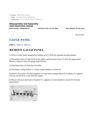
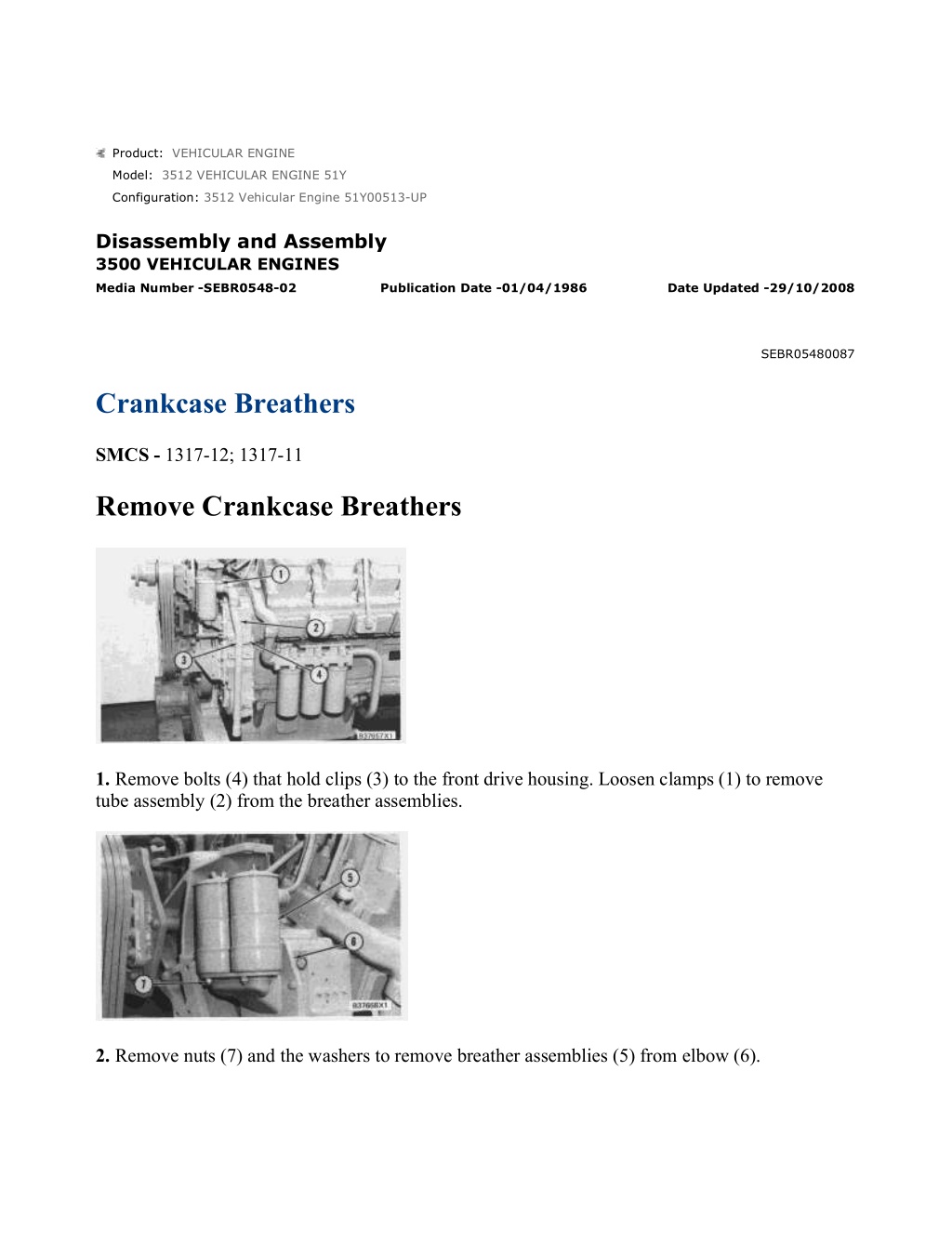
w 1/3(W) Product: VEHICULAR ENGINE Model: 3512 VEHICULAR ENGINE 51Y Configuration: 3512 Vehicular Engine 51Y00513-UP Disassembly and Assembly 3500 VEHICULAR ENGINES Media Number -SEBR0548-02 Publication Date -01/04/1986 Date Updated -29/10/2008 SEBR05480087 Crankcase Breathers SMCS - 1317-12; 1317-11 Remove Crankcase Breathers 1. Remove bolts (4) that hold clips (3) to the front drive housing. Loosen clamps (1) to remove tube assembly (2) from the breather assemblies. 2. Remove nuts (7) and the washers to remove breather assemblies (5) from elbow (6). https://127.0.0.1/sisweb/sisweb/techdoc/techdoc_print_page.jsp?returnurl=/sisweb/siswe... 2022/5/9
w 2/3(W) 3. Remove cover assembly (8) from breather assembly (5). 4. Remove element (9) from breather assembly (5). 5. Remove O-ring seals (10) from elbow (6). If necessary, remove the bolts and washers to remove elbow (6) and the gasket from the front drive housing. Install Crankcase Breather 1. If elbow (2) was removed, put the elbow with a gasket in position on the front drive housing, and install the bolts and washers to hold these in position. 2. Install O-ring seals (1) on elbow (2), and put clean engine oil on the seals. https://127.0.0.1/sisweb/sisweb/techdoc/techdoc_print_page.jsp?returnurl=/sisweb/siswe... 2022/5/9
w 3/3(W) 3. Install element (4) in breather assembly (3). 4. Install cover assembly (5) on breather assembly (3). 5. Put breather assemblies (3) in position on elbow (2), and install the nuts and washers to hold the breathers in position. 6. Put tube assembly (7) in position on the breather assemblies, and tighten clamps (6) to hold the assembly in position. Install the bolts that hold clips (8) to the front drive housing. https://127.0.0.1/sisweb/sisweb/techdoc/techdoc_print_page.jsp?returnurl=/sisweb/siswe... 2022/5/9
https://www.ebooklibonline.com Hello dear friend! Thank you very much for reading. Enter the link into your browser. The full manual is available for immediate download. https://www.ebooklibonline.com
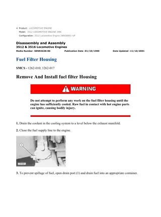
w 1/5(W) Product: VEHICULAR ENGINE Model: 3512 VEHICULAR ENGINE 51Y Configuration: 3512 Vehicular Engine 51Y00513-UP Disassembly and Assembly 3500 VEHICULAR ENGINES Media Number -SEBR0548-02 Publication Date -01/04/1986 Date Updated -29/10/2008 SEBR05480088 Water Temperature Regulators SMCS - 1355-12; 1355-11 Remove Water Temperature Regulators START BY: a. remove water temperature contactor 1. Drain the coolant from the cooling system, and disconnect the regulator housings from the radiator. 2. Remove the bolts and retainers to remove tube (1) from the engine. https://127.0.0.1/sisweb/sisweb/techdoc/techdoc_print_page.jsp?returnurl=/sisweb/siswe... 2022/5/9
w 2/5(W) 3. Remove the clamps, and remove turbocharger oil line (2) from the engine. 4. Disconnect tube assembly (3) from the regulator housings and the aftercooler adapter. Remove tube assembly (3) from the engine. 5. Remove bolts (4) that hold the regulator housings to the brackets. 6. Fasten a hoist to the regulator housings with tooling (A) as shown. Remove bolts (5), and remove the regulator housings from the engine. The weight of the housings is 63 kg (139 lb.). 7. Put the regulator housings on blocks as shown. Fasten a hoist to housing (6) with tooling (A). Remove bolts (7), and remove housing (6) from the water temperature regulators. The weight of housing (6) is 20 kg (44 lb.). https://127.0.0.1/sisweb/sisweb/techdoc/techdoc_print_page.jsp?returnurl=/sisweb/siswe... 2022/5/9
w 3/5(W) 8. Remove water temperature regulators (8) from the housing. 9. If necessary, remove seals (9) from the housing. 10. Remove ferrule (10) and the ball from the housing if necessary. Install Water Temperature Regulators 1. If the ball and ferrule were removed, install the new ball and ferrule (1) in the housing. Make sure the open end of ferrule (1) is toward the outside of the housing. Ferrule (1) must make contact with the bottom of its bore. 2. If the seals were removed, install the new seals with tool group (A) in the housing. Make sure the lip of the seals is toward the inside of the housing. https://127.0.0.1/sisweb/sisweb/techdoc/techdoc_print_page.jsp?returnurl=/sisweb/siswe... 2022/5/9
w 4/5(W) NOTICE If the water temperature regulators are installed wrong, it will cause the engine to overheat. 3. Install water temperature regulators (2) in the housing with the spring up as shown. 4. Fasten a hoist to housing (3) with tooling (B). Put the gasket and housing (3) in position on the water temperature regulators. Install the bolts to hold the housing in position. 5. Use tooling (B) to fasten a hoist to the regulator housings as shown. Put the gaskets and regulator housings in position. Install the bolts to hold the regulator housing to the water manifolds. https://127.0.0.1/sisweb/sisweb/techdoc/techdoc_print_page.jsp?returnurl=/sisweb/siswe... 2022/5/9
w 5/5(W) 6. Install bolts (5) to hold the regulator housings to the brackets. 7. Install tube assembly (4) between the regulator housings and the aftercooler adapter. 8. Install turbocharger oil line (6) and the clamp on the engine. 9. Make sure the O-ring seals on tube (7) are in position. Put clean engine oil on the seals. Install tube (7) on the engine. Install the retainers and bolts to hold the tube. 10. Connect the regulator housings to the radiator, and fill the cooling system with coolant to the correct level. See the Maintenance Guide. END BY: a. install water temperature contactor https://127.0.0.1/sisweb/sisweb/techdoc/techdoc_print_page.jsp?returnurl=/sisweb/siswe... 2022/5/9
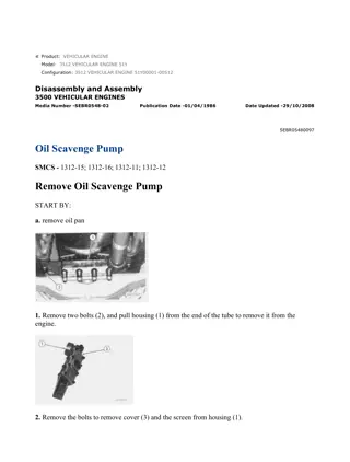
w 1/7(W) Product: VEHICULAR ENGINE Model: 3512 VEHICULAR ENGINE 51Y Configuration: 3512 Vehicular Engine 51Y00513-UP Disassembly and Assembly 3500 VEHICULAR ENGINES Media Number -SEBR0548-02 Publication Date -01/04/1986 Date Updated -29/10/2008 SEBR05480089 Water Pump SMCS - 1361-12; 1361-15; 1361-16; 1361-11 Remove Water Pump 1. Drain the coolant from the cooling system. 2. Disconnect the water pump inlet from the radiator. 3. Remove the bolts and retainers from both ends of tube (1). Remove tube (1) from the engine. 4. Fasten a hoist to water pump (3). Remove all of bolts (2) and (4) that hold the pump to the engine. Remove water pump (3) from the engine. The weight of pump (3) is 39 kg (85 lb.). https://127.0.0.1/sisweb/sisweb/techdoc/techdoc_print_page.jsp?returnurl=/sisweb/siswe... 2022/5/9
w 2/7(W) Install Water Pump 1. Make sure the gasket for the water line adapter and the O-ring seal on the pump are in position. Put clean engine oil on the O-ring seal. Fasten a hoist to water pump (1), and put water pump (1) in position on the engine. Make sure the splines on the pump shaft are correctly engaged. Install the bolts to hold the pump in position. 2. Make sure the O-ring seals on both ends of tube (2) are in position, and put clean engine oil on the seals. Put tube (2) in position, and install the retainers and bolts to hold the tube in position on the engine. 3. Connect the water pump inlet to the radiator. 4. Fill the cooling system with coolant to the correct level. See the Maintenance Guide. Disassemble Water Pump https://127.0.0.1/sisweb/sisweb/techdoc/techdoc_print_page.jsp?returnurl=/sisweb/siswe... 2022/5/9
w 3/7(W) START BY: a. remove water pump 1. Remove elbow (1) from housing assembly (2). Remove the O-ring seal from elbow (1). 2. Remove O-ring seal (5) from the back of housing assembly (2). 3. Remove washer (4) that holds shaft assembly (3) in housing assembly (2). 4. Remove cover (6) from housing assembly (2). Remove the O-ring seal from cover (6). NOTE: Later model water pumps use a nut to hold the impeller to the shaft instead of bolt (8). https://127.0.0.1/sisweb/sisweb/techdoc/techdoc_print_page.jsp?returnurl=/sisweb/siswe... 2022/5/9
w 4/7(W) 5. Loosen bolt (8) and the washer that hold impeller (7) to the pump shaft. Use tooling (A) to loosen impeller (7) from the end of the pump shaft. Remove tooling (A), bolt (8), the washer and impeller (7) from the pump shaft and housing assembly (2). 6. Remove spring (10) from seal assembly (9) and shaft assembly (3). 7. Use a soft hammer, and push shaft assembly (3) out of seal assembly (9) and housing assembly (2). Remove seal assembly (9) from housing assembly (2). 8. Remove ceramic seal (11) from the rubber ring. Remove the rubber ring from housing assembly (2). 9. Remove seal (12) from the back of housing assembly (2). Assemble Water Pump https://127.0.0.1/sisweb/sisweb/techdoc/techdoc_print_page.jsp?returnurl=/sisweb/siswe... 2022/5/9
w 5/7(W) 1. If necessary, make a replacement of the two filters in the pump housing at location (1). 2. If necessary, make a replacement of plug (2) and the seal. 3. Use tool group (A) to install the seal in the housing assembly. Make sure the lip of the seal is toward the outside as shown. Put clean engine oil on the lip of the seal. 4. Install shaft assembly (3) in housing assembly (4). Install washer (5) and the bolts to hold shaft assembly (3) in position. NOTICE Clean water only is permitted for use as a lubricant for assembly. Do not damage or put hands on the wear surface of the carbon ring or the ceramic ring. Install the ceramic ring with the smoothest face of the ring toward the carbon seal assembly. 5. Put ceramic seal (6) in position in the rubber ring. Use hand pressure and the tool (which is with the replacement seal) to install the ceramic seal. https://127.0.0.1/sisweb/sisweb/techdoc/techdoc_print_page.jsp?returnurl=/sisweb/siswe... 2022/5/9
w 6/7(W) 6. Remove the spring from seal assembly (7). Use hand pressure and the tool (which is with the replacement seal) to install the seal assembly. Push the seal assembly on the shaft until the seal faces make light contact. 7. Install spring (8) on the carbon seal assembly. 8. Put impeller (9) in position on the pump shaft as shown. 9. Install washer (11) and belt (10). Tighten bolt (10) to a torque of 90 15 N m (66 11 lb.ft.). Hit the bolt with a hammer, and tighten it again to a torque of 90 15 N m (66 11 lb.ft.). NOTE: Later model water pumps use a nut on the shaft assembly instead of bolt (10). Tighten the nut to a torque of 200 25 N m (148 18 lb.ft.). https://127.0.0.1/sisweb/sisweb/techdoc/techdoc_print_page.jsp?returnurl=/sisweb/siswe... 2022/5/9
Suggest: For more complete manuals. Please go to the home page. https://www.ebooklibonline.com If the above button click is invalid. Please download this document first, and then click the above link to download the complete manual. Thank you so much for reading
w 7/7(W) 10. Make sure the studs for cover (12) are tightened to a torque of 27 4 N m (20 3 lb.ft.) in the pump housing. 11. Put clean engine oil on O-ring seal (13), and install it on cover (12). Put cover (12) in position, and install the nuts to hold it to the pump housing. 12. Put clean engine oil on the O-ring seal, and install it in elbow (14). Put elbow (14) in position on housing assembly (4), and install the bolts to hold the unit together. 13. Put clean engine oil on the O-ring seal, and install it on the back of housing assembly (4). END BY: a. install water pump https://127.0.0.1/sisweb/sisweb/techdoc/techdoc_print_page.jsp?returnurl=/sisweb/siswe... 2022/5/9
w 1/2(W) Product: VEHICULAR ENGINE Model: 3512 VEHICULAR ENGINE 51Y Configuration: 3512 Vehicular Engine 51Y00513-UP Disassembly and Assembly 3500 VEHICULAR ENGINES Media Number -SEBR0548-02 Publication Date -01/04/1986 Date Updated -29/10/2008 SEBR05480090 Water Temperature Contactor SMCS - 7453-10 Remove And Install Water Temperature Contactor 1. Drain the coolant from the cooling system. 2. Put identification marks on the electric wires for correct installation, and disconnect them from contactor (1). 3. Remove contactor (1) from the water housing. 4. Install contactor (1) in the water housing. 5. Connect the electric wires to contactor (1). https://127.0.0.1/sisweb/sisweb/techdoc/techdoc_print_page.jsp?returnurl=/sisweb/siswe... 2022/5/9
https://www.ebooklibonline.com Hello dear friend! Thank you very much for reading. Enter the link into your browser. The full manual is available for immediate download. https://www.ebooklibonline.com