Caterpillar Cat 225 EXCAVATOR (Prefix 76U) Service Repair Manual Instant Download (76U00001-00693)
Please open the website below to get the complete manualnn// n
Download Presentation

Please find below an Image/Link to download the presentation.
The content on the website is provided AS IS for your information and personal use only. It may not be sold, licensed, or shared on other websites without obtaining consent from the author. Download presentation by click this link. If you encounter any issues during the download, it is possible that the publisher has removed the file from their server.
E N D
Presentation Transcript
Service Repair Manual Model 225EXCAVATOR
225 EXCAVATOR 76U00001-00693 (MACHINE)(UEH0804S - 00) - Documentation 1/5 Shutdown SIS Previous Screen Product: EXCAVATOR Model: 225 EXCAVATOR 76U Configuration: 225 EXCAVATOR 76U00001-00693 (MACHINE) Disassembly and Assembly 3304B and 3306B Engines for Caterpillar Built Machines Media Number -SENR5598-09 Publication Date -01/01/2013 Date Updated -25/01/2013 i00880175 Fuel Injection Lines - Remove and Install SMCS - 1252-010 Removal Procedure NOTICE Keep all parts clean from contaminants. Contaminants may cause rapid wear and shortened component life. NOTICE Care must be taken to ensure that fluids are contained during performance of inspection, maintenance, testing, adjusting and repair of the machine. Be prepared to collect the fluid with suitable containers before opening any compartment or disassembling any component containing fluids. Refer to Special Publication, NENG2500, "Caterpillar Tools and Shop Products Guide", for tools and supplies suitable to collect and contain fluids in Caterpillar machines. Dispose of all fluids according to local regulations and mandates. https://127.0.0.1/sisweb/sisweb/techdoc/techdoc_print_page.jsp?returnurl=/sis... 2019/9/11
225 EXCAVATOR 76U00001-00693 (MACHINE)(UEH0804S - 00) - Documentation 2/5 Illustration 1 g00448807 1. Remove three bolts (1), (2) and (3) and the brackets from the fuel injection lines. Illustration 2 g00448808 2. Disconnect six fuel injection line nuts (4) from the fuel injection pumps. NOTICE Do not allow the tops of the nozzles to turn while the fuel lines are loosened. The nozzles will be damaged if the top of the nozzle turns in the body. Defective fuel nozzles will damage the engine due to incorrect spray patterns. https://127.0.0.1/sisweb/sisweb/techdoc/techdoc_print_page.jsp?returnurl=/sis... 2019/9/11
https://www.ebooklibonline.com Hello dear friend! Thank you very much for reading. Enter the link into your browser. The full manual is available for immediate download. https://www.ebooklibonline.com
225 EXCAVATOR 76U00001-00693 (MACHINE)(UEH0804S - 00) - Documentation 3/5 Illustration 3 g00448809 3. Hold the tops of fuel injector nozzles (5) with a wrench, as shown. Loosen the six fuel injection line nuts at fuel injector nozzles (4) . 4. Disconnect the fuel injection line nuts at the fuel injector nozzles and remove the fuel injection lines. Put caps and plugs on all openings immediately in order to prevent dirt from contaminating the fuel system. Installation Procedure Table 1 Required Tools Tool Part Number Part Description Qty A 5P-0144 Fuel Line Socket 1 NOTICE Keep all parts clean from contaminants. Contaminants may cause rapid wear and shortened component life. NOTICE Do not allow the tops of the nozzles to turn while the fuel lines are loosened. The nozzles will be damaged if the top of the nozzle turns in the body. Defective fuel nozzles will damage the engine due to incorrect spray patterns. https://127.0.0.1/sisweb/sisweb/techdoc/techdoc_print_page.jsp?returnurl=/sis... 2019/9/11
225 EXCAVATOR 76U00001-00693 (MACHINE)(UEH0804S - 00) - Documentation 4/5 1. Remove the protective covers from the fuel line connections. Place the fuel injection lines in position on the engine. Tighten the fuel injection line nuts on the fuel injection pump and the fuel injector nozzles finger tight. Note: The nozzle assembly must be supported with a wrench. Illustration 4 g00448810 2. Hold the tops of fuel injector nozzles (1) and use Tool (A) in order to tighten the fuel injection line nuts to a torque of 40 7 N m (30 5 lb ft). Illustration 5 g00475542 3. Tighten six fuel injection line nuts (2) at the fuel injection pumps to a torque of 40 7 N m (30 5 lb ft). https://127.0.0.1/sisweb/sisweb/techdoc/techdoc_print_page.jsp?returnurl=/sis... 2019/9/11
225 EXCAVATOR 76U00001-00693 (MACHINE)(UEH0804S - 00) - Documentation 5/5 Illustration 6 g00475546 4. Install the brackets and three bolts (3), (4) and (5) that hold the fuel injection lines in position. 5. Prime the fuel system. Refer to the Operation and Maintenance Manual, "Fuel System - Prime" topic (Maintenance Section). Copyright 1993 - 2019 Caterpillar Inc. Wed Sep 11 20:12:37 UTC+0800 2019 All Rights Reserved. Private Network For SIS Licensees. https://127.0.0.1/sisweb/sisweb/techdoc/techdoc_print_page.jsp?returnurl=/sis... 2019/9/11
225 EXCAVATOR 76U00001-00693 (MACHINE)(UEH0804S - 00) - Documentation 1/3 Shutdown SIS Previous Screen Product: EXCAVATOR Model: 225 EXCAVATOR 76U Configuration: 225 EXCAVATOR 76U00001-00693 (MACHINE) Disassembly and Assembly 3304B and 3306B Engines for Caterpillar Built Machines Media Number -SENR5598-09 Publication Date -01/01/2013 Date Updated -25/01/2013 i01048513 Fuel Injection Nozzles - Remove SMCS - 1254-011 Removal Procedure Table 1 Required Tools Tool Part Number Part Description Qty A 6V-6980 Fuel Nozzle Puller 1 FT-1533 Adapter 1 B 1P-0074 Slide Hammer Puller 1 Start By: A. Remove the fuel injection lines. Refer to Disassembly and Assembly, "Fuel Injection Lines - Remove and Install". NOTICE Keep all parts clean from contaminants. Contaminants may cause rapid wear and shortened component life. NOTICE https://127.0.0.1/sisweb/sisweb/techdoc/techdoc_print_page.jsp?returnurl=/sis... 2019/9/11
225 EXCAVATOR 76U00001-00693 (MACHINE)(UEH0804S - 00) - Documentation 2/3 Do not allow the tops of the fuel injector nozzles to turn while the fuel lines are loosened. The fuel injector nozzles will be damaged if the tops of the fuel injector nozzle turns in the body. Defective fuel injector nozzles will damage the engine due to incorrect spray patterns. Illustration 1 g00448820 1. Remove bolt (1) and the clamp that secures the fuel injector nozzle. Illustration 2 g00448821 2. Install Tool (A) over the fuel injector nozzle. Turn screw (2) counterclockwise until the button on the end of the screw is just above the bolt hole for the clamp that holds down the fuel injector nozzle. 3. Tilt Tool (A) upward so that the inside lip of the fuel nozzle puller is under the diameter of the fuel injector nozzle. 4. Turn screw (2) clockwise until the button on Tool (A) goes into the bolt hole for the clamp that holds down the fuel injector nozzle. https://127.0.0.1/sisweb/sisweb/techdoc/techdoc_print_page.jsp?returnurl=/sis... 2019/9/11
225 EXCAVATOR 76U00001-00693 (MACHINE)(UEH0804S - 00) - Documentation 3/3 NOTICE Do not exceed the recommended torque on the screw of the 6V-6980 Fuel Nozzle Puller in order to remove the nozzle. The nozzle will bend or break if a torque greater than 17 N m (13 lb ft) is applied. 5. Turn screw (2) clockwise in order to lift the fuel injector nozzle out of the bore. After the fuel injector nozzle is loose in the bore of the cylinder head, move the fuel injector nozzle upward and move the fuel injector nozzle downward. Moving the fuel injector nozzle helps to loosen any carbon buildup and aids in the removal of the fuel injector nozzle. 6. When Tool (A) is used to remove the fuel injector nozzles, remove the carbon dam seal on the end of the fuel injector nozzle. Illustration 3 g00448822 7. If the fuel injector nozzle cannot be removed with Tool (A), Tool (B) must be used. Note: When Tool (B) is used, it is likely that the fuel injector nozzle cannot be used again. A new fuel injector nozzle will need to be installed as a replacement. Note: Align the centerline of Tool (B) with the extended centerline of fuel injector nozzle (3). This procedure will help prevent distortion of the fuel injector nozzle which can cause the fuel injector nozzle to bend or break. 8. Remove the protective cap and install Tool (B) . 9. Use the slide hammer in order to remove fuel injector nozzle (3) . 10. Remove the compression seal from the fuel injector nozzle. Copyright 1993 - 2019 Caterpillar Inc. Wed Sep 11 20:13:33 UTC+0800 2019 All Rights Reserved. Private Network For SIS Licensees. https://127.0.0.1/sisweb/sisweb/techdoc/techdoc_print_page.jsp?returnurl=/sis... 2019/9/11
225 EXCAVATOR 76U00001-00693 (MACHINE)(UEH0804S - 00) - Documentation 1/3 Shutdown SIS Previous Screen Product: EXCAVATOR Model: 225 EXCAVATOR 76U Configuration: 225 EXCAVATOR 76U00001-00693 (MACHINE) Disassembly and Assembly 3304B and 3306B Engines for Caterpillar Built Machines Media Number -SENR5598-09 Publication Date -01/01/2013 Date Updated -25/01/2013 i01048591 Fuel Injection Nozzles - Install SMCS - 1254-012 Installation Procedure Table 1 Required Tools Tool Part Number Part Description Qty A 6V-4979 Carbon Seal Installation Tool 1 B 8S-2245 Injector Cleaning Tool 1 C 6V-4089 Reamer 1 NOTICE Keep all parts clean from contaminants. Contaminants may cause rapid wear and shortened component life. https://127.0.0.1/sisweb/sisweb/techdoc/techdoc_print_page.jsp?returnurl=/sis... 2019/9/11
225 EXCAVATOR 76U00001-00693 (MACHINE)(UEH0804S - 00) - Documentation 2/3 Illustration 1 g00448903 1. Put carbon dam seal (1) on the small end of Tool (A). Expand carbon dam seal (1) by sliding carbon dam seal (1) to the large end of Tool (A). Put Tool (A) against the fuel injector nozzle. Slide carbon dam seal (1) from Tool (A) to the fuel injector nozzle. Slide carbon dam seal (1) into position in the groove of the fuel injector nozzle, as shown. Use Tool (A) in order to install carbon dam seal (1). 2. To clean the fuel injector nozzles, refer to Special Instruction, SEHS7292 for the use of Tool (B) . 3. Install a new compression seal (2) on the fuel injector nozzle. Illustration 2 g00448904 4. Use Tool (C) in order to clean the bore in the cylinder head for the fuel injector nozzle. Use a wrench in order to turn Tool (C) . https://127.0.0.1/sisweb/sisweb/techdoc/techdoc_print_page.jsp?returnurl=/sis... 2019/9/11
225 EXCAVATOR 76U00001-00693 (MACHINE)(UEH0804S - 00) - Documentation 3/3 Illustration 3 g00448905 Illustration 4 g00448906 5. Align notch (3) in fuel injector nozzle (5) to the tab in clamp (4) during installation. 6. Install fuel injector nozzle (5). Ensure that the notch in the injector is aligned with the tab in clamp (4) . End By: Install the fuel injection lines. Refer to Disassembly and Assembly, "Fuel Injection Lines - Remove and Install". Copyright 1993 - 2019 Caterpillar Inc. Wed Sep 11 20:14:28 UTC+0800 2019 All Rights Reserved. Private Network For SIS Licensees. https://127.0.0.1/sisweb/sisweb/techdoc/techdoc_print_page.jsp?returnurl=/sis... 2019/9/11
225 EXCAVATOR 76U00001-00693 (MACHINE)(UEH0804S - 00) - Documentation 1/2 Shutdown SIS Previous Screen Product: EXCAVATOR Model: 225 EXCAVATOR 76U Configuration: 225 EXCAVATOR 76U00001-00693 (MACHINE) Disassembly and Assembly 3304B and 3306B Engines for Caterpillar Built Machines Media Number -SENR5598-09 Publication Date -01/01/2013 Date Updated -25/01/2013 i00903297 Fuel Ratio Control - Remove SMCS - 1278-011 Removal Procedure NOTICE Keep all parts clean from contaminants. Contaminants may cause rapid wear and shortened component life. NOTICE Care must be taken to ensure that fluids are contained during performance of inspection, maintenance, testing, adjusting and repair of the machine. Be prepared to collect the fluid with suitable containers before opening any compartment or disassembling any component containing fluids. Refer to Special Publication, NENG2500, "Caterpillar Tools and Shop Products Guide", for tools and supplies suitable to collect and contain fluids in Caterpillar machines. Dispose of all fluids according to local regulations and mandates. https://127.0.0.1/sisweb/sisweb/techdoc/techdoc_print_page.jsp?returnurl=/sis... 2019/9/11
225 EXCAVATOR 76U00001-00693 (MACHINE)(UEH0804S - 00) - Documentation 2/2 Illustration 1 g00460630 1. Disconnect fuel pressure line (3). Remove two bolts (2) . 2. Move fuel ratio control (1) upward in order to disengage the fuel ratio control from the lever assembly in the governor. Illustration 2 g00460631 3. Remove four O-ring seals (4) and screen assembly (5) . Copyright 1993 - 2019 Caterpillar Inc. Wed Sep 11 20:15:24 UTC+0800 2019 All Rights Reserved. Private Network For SIS Licensees. https://127.0.0.1/sisweb/sisweb/techdoc/techdoc_print_page.jsp?returnurl=/sis... 2019/9/11
225 EXCAVATOR 76U00001-00693 (MACHINE)(UEH0804S - 00) - Documentation 1/3 Shutdown SIS Previous Screen Product: EXCAVATOR Model: 225 EXCAVATOR 76U Configuration: 225 EXCAVATOR 76U00001-00693 (MACHINE) Disassembly and Assembly 3304B and 3306B Engines for Caterpillar Built Machines Media Number -SENR5598-09 Publication Date -01/01/2013 Date Updated -25/01/2013 i00903551 Fuel Ratio Control - Disassemble SMCS - 1278-015 Disassembly Procedure Table 1 Required Tools Tool Part Number Part Description Qty A FT-1820 Fixture Assembly 1 B 1P-1855 Retaining Ring Pliers 1 C 6V-9072 Guide 1 Start By: A. Remove the fuel ratio control. Refer to Disassembly and Assembly, "Fuel Ratio Control - Remove". NOTICE Keep all parts clean from contaminants. Contaminants may cause rapid wear and shortened component life. https://127.0.0.1/sisweb/sisweb/techdoc/techdoc_print_page.jsp?returnurl=/sis... 2019/9/11
225 EXCAVATOR 76U00001-00693 (MACHINE)(UEH0804S - 00) - Documentation 2/3 Illustration 1 g00460737 1. Remove cover (1) and O-ring seal (2) . Personal injury can result from parts and/or covers under spring pressure. Spring force will be released when covers are removed. Be prepared to hold spring loaded covers as the bolts are loosened. 2. In order to release the spring force, hold cover (3) in position and slowly remove the two bolts that hold cover (3) in place. Illustration 2 g00460791 3. Remove spring (4), washer (5) and diaphragm (6) from retainer (7). Remove retainer (7) from housing (8) . https://127.0.0.1/sisweb/sisweb/techdoc/techdoc_print_page.jsp?returnurl=/sis... 2019/9/11
225 EXCAVATOR 76U00001-00693 (MACHINE)(UEH0804S - 00) - Documentation 3/3 Illustration 3 g00460793 4. Remove nut (13) from valve extension (12) and remove valve extension (12) from retainer (7). Remove stem (9) from valve extension (12). Remove spring (10) and O-ring seal (11) from valve extension (12) . Illustration 4 g00460795 5. Remove spring (14) and retainer (15) from housing (8) . 6. All parts should be cleaned and inspected. Replace all parts that are worn or damaged. Copyright 1993 - 2019 Caterpillar Inc. Wed Sep 11 20:16:20 UTC+0800 2019 All Rights Reserved. Private Network For SIS Licensees. https://127.0.0.1/sisweb/sisweb/techdoc/techdoc_print_page.jsp?returnurl=/sis... 2019/9/11
225 EXCAVATOR 76U00001-00693 (MACHINE)(UEH0804S - 00) - Documentation 1/4 Shutdown SIS Previous Screen Product: EXCAVATOR Model: 225 EXCAVATOR 76U Configuration: 225 EXCAVATOR 76U00001-00693 (MACHINE) Disassembly and Assembly 3304B and 3306B Engines for Caterpillar Built Machines Media Number -SENR5598-09 Publication Date -01/01/2013 Date Updated -25/01/2013 i01135000 Fuel Ratio Control - Assemble SMCS - 1278-016 Assembly Procedure Table 1 Required Tools Tool Part Number Part Description Qty A FT-1820 Fixture Assembly 1 B 1P-1855 Retaining Ring Pliers 1 C 6V-9072 Guide 1 NOTICE Keep all parts clean from contaminants. Contaminants may cause rapid wear and shortened component life. Note: Check the condition of the O-ring and the diaphragm. If the O-ring or the diaphragm is worn or damaged use new parts for replacement. https://127.0.0.1/sisweb/sisweb/techdoc/techdoc_print_page.jsp?returnurl=/sis... 2019/9/11
225 EXCAVATOR 76U00001-00693 (MACHINE)(UEH0804S - 00) - Documentation 2/4 Illustration 1 g00460801 1. Install spring (1) and retainer (2) into housing (3) . Illustration 2 g00460828 2. Install O-ring seal (6) and spring (5) into valve extension (7). Install stem (4) into valve extension (7). Secure valve extension (7) to retainer (8) with nut (9) . Illustration 3 g00460830 https://127.0.0.1/sisweb/sisweb/techdoc/techdoc_print_page.jsp?returnurl=/sis... 2019/9/11
225 EXCAVATOR 76U00001-00693 (MACHINE)(UEH0804S - 00) - Documentation 3/4 3. Install stem (4) and retainer (8) into housing (3) . Illustration 4 g00460912 4. Install diaphragm (12), washer (11) and spring (10) on retainer (8) . Illustration 5 g00460914 Illustration 6 g00460917 https://127.0.0.1/sisweb/sisweb/techdoc/techdoc_print_page.jsp?returnurl=/sis... 2019/9/11
225 EXCAVATOR 76U00001-00693 (MACHINE)(UEH0804S - 00) - Documentation 4/4 5. Install cover (13) on housing (3). Secure cover (13) with two bolts and washers. 6. Install O-ring seal (15) onto cover (14) and install cover (14) onto cover (13). Secure cover (14) with two bolts. Note: Refer to Testing and Adjusting, "Fuel System" for additional information on the adjustment procedure for the fuel ratio control. End By: Install the fuel ratio control. Refer to Disassembly and Assembly, "Fuel Ratio Control - Install". Copyright 1993 - 2019 Caterpillar Inc. Wed Sep 11 20:17:16 UTC+0800 2019 All Rights Reserved. Private Network For SIS Licensees. https://127.0.0.1/sisweb/sisweb/techdoc/techdoc_print_page.jsp?returnurl=/sis... 2019/9/11
225 EXCAVATOR 76U00001-00693 (MACHINE)(UEH0804S - 00) - Documentation 1/2 Shutdown SIS Previous Screen Product: EXCAVATOR Model: 225 EXCAVATOR 76U Configuration: 225 EXCAVATOR 76U00001-00693 (MACHINE) Disassembly and Assembly 3304B and 3306B Engines for Caterpillar Built Machines Media Number -SENR5598-09 Publication Date -01/01/2013 Date Updated -25/01/2013 i00903481 Fuel Ratio Control - Install SMCS - 1278-012 Installation Procedure NOTICE Keep all parts clean from contaminants. Contaminants may cause rapid wear and shortened component life. Illustration 1 g00460631 1. Screen assembly (5) and four O-ring seals (4) should be inspected, replaced and installed. https://127.0.0.1/sisweb/sisweb/techdoc/techdoc_print_page.jsp?returnurl=/sis... 2019/9/11
225 EXCAVATOR 76U00001-00693 (MACHINE)(UEH0804S - 00) - Documentation 2/2 Illustration 2 g00460630 2. Put fuel ratio control (1) in position and engage the fuel ratio control with the lever assembly in the governor. 3. Install bolts (2) that hold the fuel ratio control and connect fuel pressure line (3) to fuel ratio control (1). Refer to Testing and Adjusting, "Fuel System" for more information on the adjustment procedure for the fuel ratio control. Copyright 1993 - 2019 Caterpillar Inc. Wed Sep 11 20:18:11 UTC+0800 2019 All Rights Reserved. Private Network For SIS Licensees. https://127.0.0.1/sisweb/sisweb/techdoc/techdoc_print_page.jsp?returnurl=/sis... 2019/9/11
225 EXCAVATOR 76U00001-00693 (MACHINE)(UEH0804S - 00) - Documentation 1/2 Shutdown SIS Previous Screen Product: EXCAVATOR Model: 225 EXCAVATOR 76U Configuration: 225 EXCAVATOR 76U00001-00693 (MACHINE) Disassembly and Assembly 3304B and 3306B Engines for Caterpillar Built Machines Media Number -SENR5598-09 Publication Date -01/01/2013 Date Updated -25/01/2013 i00879991 Fuel Shutoff Solenoid - Remove and Install SMCS - 1259-010 Removal Procedure NOTICE Keep all parts clean from contaminants. Contaminants may cause rapid wear and shortened component life. Illustration 1 g00475568 1. Remove nut (1) and the washer. Disconnect ground wire (4) from the fuel shutoff solenoid. 2. Remove two nuts (2) and the washers. https://127.0.0.1/sisweb/sisweb/techdoc/techdoc_print_page.jsp?returnurl=/sis... 2019/9/11
225 EXCAVATOR 76U00001-00693 (MACHINE)(UEH0804S - 00) - Documentation 2/2 3. Remove fuel shutoff solenoid (3) and the gasket. Installation Procedure NOTICE Keep all parts clean from contaminants. Contaminants may cause rapid wear and shortened component life. Illustration 2 g00475568 1. Install the gasket and fuel shutoff solenoid (3) . 2. Apply 9S-3263 Thread Lock Compound on the threads for two nuts (2) . 3. Install the washers and two nuts (2) . 4. Connect ground wire (4) to the fuel shutoff solenoid. Install nut (1) and the washer. Copyright 1993 - 2019 Caterpillar Inc. Wed Sep 11 20:19:07 UTC+0800 2019 All Rights Reserved. Private Network For SIS Licensees. https://127.0.0.1/sisweb/sisweb/techdoc/techdoc_print_page.jsp?returnurl=/sis... 2019/9/11
225 EXCAVATOR 76U00001-00693 (MACHINE)(UEH0804S - 00) - Documentation 1/4 Shutdown SIS Previous Screen Product: EXCAVATOR Model: 225 EXCAVATOR 76U Configuration: 225 EXCAVATOR 76U00001-00693 (MACHINE) Disassembly and Assembly 3304B and 3306B Engines for Caterpillar Built Machines Media Number -SENR5598-09 Publication Date -01/01/2013 Date Updated -25/01/2013 i00930839 Automatic Timing Advance - Remove SMCS - 1272-011 Removal Procedure Table 1 Required Tools Tool Part Number Part Description Qty A 5P-7307 Engine Turning Tool 1 B 0T-0065 Bolt 1 9S-9155 Spacer 1 8S-2264 Pump Impeller Puller 2 C 0T-0513 Bolt 2 5P-1075 Hard Washer 2 Start By: A. Remove the front housing. Refer to Disassembly and Assembly, "Front Housing - Remove". NOTICE Keep all parts clean from contaminants. Contaminants may cause rapid wear and shortened component life. https://127.0.0.1/sisweb/sisweb/techdoc/techdoc_print_page.jsp?returnurl=/sis... 2019/9/11
Suggest: If the above button click is invalid. Please download this document first, and then click the above link to download the complete manual. Thank you so much for reading
225 EXCAVATOR 76U00001-00693 (MACHINE)(UEH0804S - 00) - Documentation 2/4 1. Follow the procedure in Steps 3 and 4 in order to time the fuel injection pump when the front cover is removed. Follow the procedure in Steps 6 and 7 in order to time the fuel injection pump when the front cover is installed. Note: The No. 1 piston should be at the top center position on the compression stroke at the start of all timing procedures. Note: The engine is seen from the flywheel end when the direction of the crankshaft rotation is given. Illustration 1 g00474593 2. Remove the electric starting motor and install Tool (A) . Illustration 2 g00474592 3. Turn the crankshaft counterclockwise until the "C" on the crankshaft gear and the "C" on the camshaft gear are in alignment. https://127.0.0.1/sisweb/sisweb/techdoc/techdoc_print_page.jsp?returnurl=/sis... 2019/9/11
https://www.ebooklibonline.com Hello dear friend! Thank you very much for reading. Enter the link into your browser. The full manual is available for immediate download. https://www.ebooklibonline.com

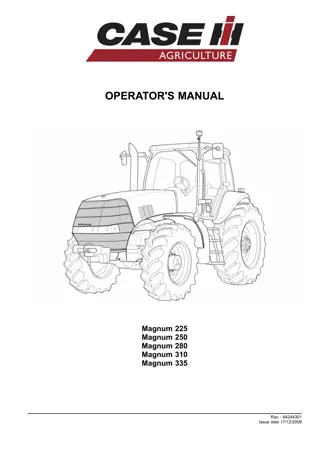
![CASE IH Magnum 225 Tractor Service Repair Manual Instant Download [Z8Rx06001 - ]](/thumb/105097/case-ih-magnum-225-tractor-service-repair-manual-instant-download-z8rx06001.jpg)
