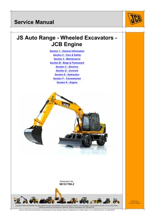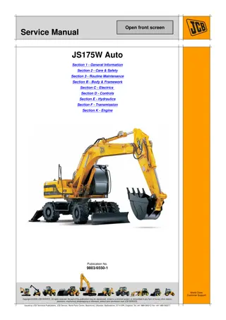
CASE WX218 Wheeled Excavator Service Repair Manual Instant Download
Please open the website below to get the complete manualnn//
Download Presentation

Please find below an Image/Link to download the presentation.
The content on the website is provided AS IS for your information and personal use only. It may not be sold, licensed, or shared on other websites without obtaining consent from the author. Download presentation by click this link. If you encounter any issues during the download, it is possible that the publisher has removed the file from their server.
E N D
Presentation Transcript
SERVICE MANUAL WX218 WX218 Wheeled Excavator Wheeled Excavator 1/1 SERVICE MANUAL Part number 48005326 Part number 48005326 English April 2016 2016 CNH Industrial Italia S.p.A. All Rights Reserved.
SERVICE MANUAL WX218 48005326 27/04/2016 EN
Link Product / Engine Product Market Product Asia Pacific Europe Middle East Africa Engine WX218 WX218 WX218 F4GE9684 F4GE9684 F4GE9684 48005326 27/04/2016
https://www.ebooklibonline.com Hello dear friend! Thank you very much for reading. Enter the link into your browser. The full manual is available for immediate download. https://www.ebooklibonline.com
Contents INTRODUCTION Engine....................................................................................... 10 [10.202] Air cleaners and lines .............................................................. 10.1 [10.206] Fuel filters .......................................................................... 10.2 [10.216] Fuel tanks .......................................................................... 10.3 [10.218] Fuel injection system............................................................... 10.4 [10.254] Intake and exhaust manifolds and muffler ......................................... 10.5 [10.310] Aftercooler.......................................................................... 10.6 [10.400] Engine cooling system ............................................................. 10.7 Transmission.............................................................................. 21 [21.105] Powershift transmission lubrication system........................................ 21.1 [21.113] Powershift transmission ............................................................ 21.2 [21.135] Powershift transmission external controls.......................................... 21.3 [21.155] Powershift transmission internal components...................................... 21.4 Four-Wheel Drive (4WD) system .................................................. 23 [23.314] Drive shaft.......................................................................... 23.1 Front axle system ....................................................................... 25 [25.100] Powered front axle ................................................................. 25.1 [25.102] Front bevel gear set and differential ............................................... 25.2 [25.108] Final drive hub, steering knuckles, and shafts ..................................... 25.3 [25.122] Axle suspension control............................................................ 25.4 Rear axle system........................................................................ 27 [27.100] Powered rear axle.................................................................. 27.1 [27.106] Rear bevel gear set and differential................................................ 27.2 [27.120] Planetary and final drives .......................................................... 27.3 Brakes and controls .................................................................... 33 48005326 27/04/2016
[33.110] Parking brake or parking lock ...................................................... 33.1 [33.202] Hydraulic service brakes ........................................................... 33.2 Hydraulic systems....................................................................... 35 [35.000] Hydraulic systems.................................................................. 35.1 [35.106] Variable displacement pump ....................................................... 35.2 [35.300] Reservoir, cooler, and filters........................................................ 35.3 [35.304] Combination pump units ........................................................... 35.4 [35.352] Hydraulic swing system ............................................................ 35.5 [35.353] Hydraulic travel system ............................................................ 35.6 [35.354] Hydraulic central joint .............................................................. 35.7 [35.357] Pilot system ........................................................................ 35.8 [35.359] Main control valve.................................................................. 35.9 [35.360] Hammer and rotating bucket hydraulic system .................................. 35.10 [35.703] Stabilizer hydraulic system....................................................... 35.11 [35.730] Positioning arm hydraulic system ................................................ 35.12 [35.736] Boom hydraulic system .......................................................... 35.13 [35.737] Dipper hydraulic system.......................................................... 35.14 [35.738] Excavator and backhoe bucket hydraulic system................................ 35.15 [35.741] Dozer blade cylinders ............................................................ 35.16 Frames and ballasting................................................................. 39 [39.103] Swing ring assembly ............................................................... 39.1 [39.129] Stabilizers .......................................................................... 39.2 [39.140] Ballasts and supports .............................................................. 39.3 Steering..................................................................................... 41 [41.101] Steering control .................................................................... 41.1 [41.106] Tie rods............................................................................. 41.2 [41.200] Hydraulic control components...................................................... 41.3 [41.216] Cylinders ........................................................................... 41.4 48005326 27/04/2016
Wheels...................................................................................... 44 [44.511] Front wheels........................................................................ 44.1 [44.520] Rear wheels........................................................................ 44.2 Cab climate control..................................................................... 50 [50.200] Air conditioning..................................................................... 50.1 Electrical systems....................................................................... 55 [55.000] Electrical system ................................................................... 55.1 [55.010] Fuel injection system............................................................... 55.2 [55.011] Fuel tank system ................................................................... 55.3 [55.012] Engine cooling system ............................................................. 55.4 [55.014] Engine intake and exhaust system................................................. 55.5 [55.015] Engine control system.............................................................. 55.6 [55.020] Transmission speed sensors....................................................... 55.7 [55.036] Hydraulic system control ........................................................... 55.8 [55.050] Heating, Ventilation, and Air-Conditioning (HVAC) control system................. 55.9 [55.100] Harnesses and connectors....................................................... 55.10 [55.110] Electrical rotary joint.............................................................. 55.11 [55.302] Battery............................................................................ 55.12 [55.404] External lighting .................................................................. 55.13 [55.416] Swing control system ............................................................ 55.14 [55.425] Boom, dipper, and bucket control system........................................ 55.15 [55.512] Cab controls...................................................................... 55.16 [55.514] Cab lighting ...................................................................... 55.17 [55.525] Cab engine controls.............................................................. 55.18 [55.530] Camera........................................................................... 55.19 [55.640] Electronic modules............................................................... 55.20 Booms, dippers, and buckets ....................................................... 84 [84.100] Bucket.............................................................................. 84.1 48005326 27/04/2016
[84.910] Boom............................................................................... 84.2 Dozer blade and arm................................................................... 86 [86.110] Dozer blade ........................................................................ 86.1 Platform, cab, bodywork, and decals............................................. 90 [90.118] Protections and footboards......................................................... 90.1 [90.124] Pneumatically-adjusted operator seat.............................................. 90.2 [90.150] Cab................................................................................. 90.3 [90.151] Cab interior......................................................................... 90.4 48005326 27/04/2016
INTRODUCTION 48005326 27/04/2016 1
INTRODUCTION Foreword - Important notice regarding equipment servicing All repair and maintenance work listed in this manual must be carried out only by qualified dealership personnel, strictly complying with the instructions given, and using, whenever possible, the special tools. Anyone who performs repair and maintenance operations without complying with the procedures provided herein shall be responsible for any subsequent damages. The manufacturer and all the organizations of its distribution chain, including - without limitation - national, regional, or local dealers, reject any responsibility for damages caused by parts and/or components not approved by the manu- facturer, including those used for the servicing or repair of the product manufactured or marketed by the manufacturer. In any case, no warranty is given or attributed on the product manufactured or marketed by the manufacturer in case of damages caused by parts and/or components not approved by the manufacturer. The manufacturer reserves the right to make improvements in design and changes in specifications at any time without notice and without incurring any obligation to install them on units previously sold. Specifications, descriptions, and illustrative material herein are as accurate as known at time of publication but are subject to change without notice. In case of questions, refer to your CASE CONSTRUCTION Sales and Service Networks. 48005326 27/04/2016 3
INTRODUCTION Safety rules Personal safety This is the safety alert symbol. It is used to alert you to potential personal injury hazards. Obey all safety messages that follow this symbol to avoid possible death or injury. Throughout this manual you will find the signal words DANGER, WARNING, and CAUTION followed by special in- structions. These precautions are intended for the personal safety of you and those working with you. Read and understand all the safety messages in this manual before you operate or service the machine. DANGER indicates a hazardous situation that, if not avoided, will result in death or serious injury. WARNING indicates a hazardous situation that, if not avoided, could result in death or serious injury. CAUTION indicates a hazardous situation that, if not avoided, could result in minor or moderate injury. FAILURE TO FOLLOW DANGER, WARNING, AND CAUTION MESSAGES COULD RESULT IN DEATH OR SERIOUS INJURY. Machine safety NOTICE: Notice indicates a situation that, if not avoided, could result in machine or property damage. Throughout this manual you will find the signal word Notice followed by special instructions to prevent machine or property damage. The word Notice is used to address practices not related to personal safety. Information NOTE: Note indicates additional information that clarifies steps, procedures, or other information in this manual. Throughout this manual you will find the word Note followed by additional information about a step, procedure, or other information in the manual. The word Note is not intended to address personal safety or property damage. 48005326 27/04/2016 4
INTRODUCTION Personal safety Carefully read this Manual before proceeding with main- tenance, repairs, refuelling or other machine operations. Repairs have to be carried out only by authorized and in- structed staff; specific precautions have to be taken when grinding, welding or when using mallets or heavy ham- mers. Not authorized persons are not allowed to repair or carry out maintenance on this machine. Do not carry out any work on the equipment without prior authorization. Ask your employer about the safety instructions in force and safety equipment. 1 TULI12WEX2004AA Nobody should be allowed in the cab during machine maintenance unless he is a qualified operator helping with the maintenance work. If it is necessary to move the equipment to carry out re- pairs or maintenance, do not lift or lower the equipment from any other position than the operator s seat. Never carry out any operation on the machine when the engine is running, except when specifically indicated. Stop the engine and ensure that all pressure is relieved from hydraulic circuits before removing caps, covers, valves, etc. All repair and maintenance operations should be carried out with the greatest care and attention. Service stairs and platforms used in a workshop or in the field should be built in compliance with the safety rules in force. 2 TULI12WEX2005AA Any functional disorders, especially those affecting the safety of the machine, should therefore be rectified im- mediately. DANGER Unexpected movement! Make sure parking brake is applied. Secure machine with wheel chocks. Failuretocomplywillresultindeathorserious injury. D0013A Before performing any work on the machine, attach a maintenance in progress tag. This tag can be applied on the left-hand control lever, safety lever or cab door. 48005326 27/04/2016 5
INTRODUCTION Product overview Triple Articulation Version 1 SMIL13WEX0039GB 1 2 3 4 5 6 7 8 Bucket cylinder Dipper Dipper cylinder Second boom Positioning cylinder Muffler Radiators Batteries 9 10 Rear rigid axle 11 Stair and storage box 12 Front wheels 13 Front steering axle 14 Axle floating locking cylinder 15 Upper structure Rear wheels 48005326 27/04/2016 44
SERVICE MANUAL Engine WX218 48005326 27/04/2016 10
Engine - Air cleaners and lines Air cleaners and lines - Static description The support (1) attaches the air cleaner (2) to the frame of the machine. The air cleaner (2) filters the intake air of the engine. The filtered air flows into the hose (3). 1 SMIL13WEX0075GB 48005326 27/04/2016 10.1 [10.202] / 3
Engine - Air cleaners and lines The air cleaner consists of: a cover (1); a locking clip (2); two filter elements (3) and (4); a case (5); a dust charge valve (6). 2 TULI12WEX2146AB 48005326 27/04/2016 10.1 [10.202] / 4
Engine - Air cleaners and lines Air intake lines - Remove Remove the hose (1). 1. Loosen the three clamps (6). 2. Disconnect the two ends of the hose and remove it. Remove the hose (2). 3. Loosen the two clamps (4). 4. Disconnect the two ends of the hose and remove it. Remove the hose (3). 5. Loosen the two clamps (5) 6. Disconnect the two ends of the hose and remove it. 1 SMIL13WEX0077AB 48005326 27/04/2016 10.1 [10.202] / 5
Engine - Air cleaners and lines Air intake lines - Install Install the hose (1). 1. Connect the two ends of the hose. 2. Install the clamps (6) and tighten them to 5.9 N m (4.4 lb ft). Install the hose (2). 1. Connect the two ends of the hose. 2. Install the clamps (4) and tighten them to 5.9 N m (4.4 lb ft). Install the hose (3). 1. Connect the two ends of the hose. 1 SMIL13WEX0077AB 2. Install the clamps (5) and tighten them to 5.9 N m (4.4 lb ft). 48005326 27/04/2016 10.1 [10.202] / 6
Engine - Air cleaners and lines Air cleaner support - Remove 1. Unscrew the three screws (1) and remove screws, washers and nuts. 2. Unscrewsthefourscrews(2), removescrews, washers and nuts. Remove the support (3). 1 SMIL13WEX0076AB 48005326 27/04/2016 10.1 [10.202] / 7
Engine - Air cleaners and lines Air cleaner support - Install 1. Apply LOCTITE 242 on the three screws (1) of the support (3). Install the screws, the washers and the nuts. Tighten to 39.2 N m (28.9 lb ft). 2. Apply LOCTITE 242 on the four screws (2). Install the screws, the washers and the nuts. Tighten to 39.2 N m (28.9 lb ft). 1 SMIL13WEX0076AB 48005326 27/04/2016 10.1 [10.202] / 8
Engine - Air cleaners and lines Air cleaner - Replace Open the cover on the left side of the machine. Remove the air cleaner sensor (A). 1 SMIL13WEX0078AB Push the clip (2) forward, turn the filter cover (1) to the left and remove it. The dust discharge valve (6) is included into the filter cover (1). Remove the main filter element (3) carefully from the case (5). Remove from the case (5) also the filter element (4). NOTE: Beyond respecting the maintenance interval of the safety element (4), this has to be replaced after the main element (3) has been cleaned three times. Clean the inside of the filter case (5) and the cover (1) accurately, by means of a vacuum cleaner. Install the new safety element (4) and then the main new element (3). Reassemble the cover (1) and lock it with the fastener (2). Re-install the sensor (A) on the air cleaner. Tighten the sensor (A) to 3.9 N m (2.9 lb ft). 2 TULI12WEX2146AB 48005326 27/04/2016 10.1 [10.202] / 9
Engine - Fuel filters Fuel filters - Replace NOTICE: To work in safety, switch off and let the cooling of engine before work. NOTICE: Dispose worn out filters respecting the current environmental legislation. Open the right door (1) to access to the fuel filters. Replace fuel filters according to maintenance plan or in case of damage. To replace, operate as follow. 1 F00384N1 1. Remove the filter elements (1) from support (2). Take care to collect the fuel that comes out. 2. Clean the support surface. 3. Fill of fuel the new filter elements. 4. Lubricate the seal of the new filter elements. 5. Tighten the filter elements on support. 2 TULI12WEX2167AB 48005326 27/04/2016 10.2 [10.206] / 3
Engine - Fuel filters Fuel-water separator filter - Drain fluid NOTICE: To work in safety, switch off and let the cooling of engine before work. NOTE: Water in fuel can cause corrosion and engine dam- age. Open the right door (1) to access to the fuel-water sep- arator filter. 1 F00384N1 Fuel-water separator filters impurity and separates the water present in fuel. A sensor (1) is located on draining valve (2) of water separator (3). 2 TULI12WEX2164AB It causes the lighting of red light (5) on multifunction display (4) (with displaying of fault code 7048 water in fuel ), each time water is detected into the water sepa- rator. At the same time an acoustic signal is activated. NOTICE: Immediately drain water from water separator when fault code 7048 (4) and red light (5) appear on dis- play. If within 30 min the fault code appears again, drain water from tank. 1. Gainaccesstothewaterseparatorfilter(3)openingthe right door of upper structure. 2. Place a container under the water separator to collect the water. 3 SMIL12WEX0319AB 3. Disconnect the connector (1). 4. Open the drain valve (2), (located in the bottom part of water separator) and let water draining. 5. When fuel comes out, close the drain valve (2). 6. Connect the connector (1). 7. Check the sealing of water separator filter. 48005326 27/04/2016 10.2 [10.206] / 4
Engine - Fuel filters Fuel-water separator filter - Bleed NOTICE: To work in safety, switch off and let the cooling of engine before work. Gain access to the water separator filter (1) opening the right door of upper structure. 1 F00384N1 Air accumulation is possible into the filter (1). To bleed air operate as follow. 1. Loosen the bleeding screw (2). 2. Connect a rubber hose to the bleeding screw (2) to direct the fuel into a fuel collecting container. 3. Manually operate on pump (3) until fuel comes out with- out air bubbles from rubber hose. 4. Disconnect the rubber hose. 5. Tighten the bleeding screw (2). 2 TULI12WEX2166AB 48005326 27/04/2016 10.2 [10.206] / 5
Engine - Fuel filters Fuel-water separator filter - Replace NOTICE: To work in safety, switch off and let the cooling of engine before work. NOTICE: Dispose worn out filters respecting the current environmental legislation. Open the right door (1) to access to the water separator filter. 1 F00384N1 Do not clean the water separator, but replace it accord- ing to the maintenance plan. 1. Disconnect the connector of the sensor (3). 2. Remove the filter element (1) from water separator (2). Pay attention to not pour fuel. 3. Clean the support surface. 4. Fill the new filter element with fuel. 5. Lubricate the seal of the new filter element. 6. Tighten the filter element on water separator. 7. Connect the connector of the sensor (3). 8. If engine does not start, bleed air from fuel hoses. 2 TULI12WEX2681AB 9. After few minutes, check sealing between filter element and water separator. 48005326 27/04/2016 10.2 [10.206] / 6
Engine - Fuel tanks Fuel tanks - Exploded view The fuel tank contains the fuel for the engine. 1 SMIL16WEX0041FB 1. 2. 3. 4. 5. Fuel tank Flexible hose Water separator Fuel filters Diesel engine 6. 7. 8. 9. Drain cock Fuel transfer pump Fuel level sensor Refuelling pump sensor 48005326 27/04/2016 10.3 [10.216] / 3
Engine - Fuel tanks Fuel tank - Drain fluid Draining condensation WARNING Fuel vapors are explosive and flammable. Do not smoke while handling fuel. Keep fuel away from flames or sparks. Shut off engine and remove key before servicing. Always work in a well-ventilated area. Clean up spilled fuel immediately. Failure to comply could result in death or seri- ous injury. W0904A To drain the condensation inside the fuel tank, proceed as follows: 1 N00436M Park the machine on a level surface. Rest the bucket to the ground. Deactivate the Auto-Idle function, turn the engine speed throttle to LOW IDLE position, stop the en- gine, extract the starter key and place the safety lever in LOCK position. Get under the turret in correspondence with the fuel tank and remove the guard. Remove plug (1) from draining valve. Slowly open the cock (2) and let condensation and deposits drain into a suitable container until only clean fuel comes out. Once the draining operation is over, close cock (2), reinstall plug (1) and the guard. Bleed air from the fuel system. NOTE: when the temperature is above 0 C, draining can be done before engine start-up. When working with tem- peraturesbelow0 C,thetankshouldbedrainedattheend of work, after engine stop, as water might freeze and not drain properly. 48005326 27/04/2016 10.3 [10.216] / 4
Engine - Fuel tanks Fuel tank - Remove 1. Park the machine on a level and firm surface. 2. Engage the parking brake. 3. Lock the upper structure. 4. Stop the engine. 5. Empty the fuel tank. Fuel tank capacity is 300 L (66 UK gal). 6. Remove the screws and the washers (1) and remove the handrails (2). 1 SMIL13WEX0085AB 7. Under the upper structure, disconnect the delivery and return hoses (3) from fuel tank (4). 2 TULI12WEX2158AB 8. Gain access to the upper part of fuel tank (4) and dis- connect the connector of fuel level sensor (5), the con- nector of refueling pump sensor (6) and the refueling hose (7). NOTICE: Fuel tank weights 113 kg (249 lb). Use suitable tools to lift the fuel tank. 3 TULI12WEX2159AB 48005326 27/04/2016 10.3 [10.216] / 5
Engine - Fuel tanks 9. Remove the two screws (10) to remove the expansion tank (11) from the fuel tank (4). 4 SMIL13WEX0092AB 10. Suitably sling the fuel tank. Remove the four attaching screws (8) and the four washers (9) from the bottom of fuel tank. Remove the fuel tank. 5 TULI12WEX2160AB 48005326 27/04/2016 10.3 [10.216] / 6
Engine - Fuel tanks Fuel tank - Install 1. Position the fuel tank on upper structure frame. NOTICE: Fuel tank weights 113 kg (249 lb). Use suitable tools to lift the fuel tank. 2. Apply LOCTITE 262 on screws (8). 3. Install the four washers (9) and the four attaching screws (8). 4. Tighten the screws (8) to 216 N m (159 lb ft). 1 TULI12WEX2160AB 5. Gain access the upper part of fuel tank (4) and con- nect the fuel level sensor (5), the connector of refueling pump sensor (6) and the refueling hose (7). Tighten the hose to 6.86 N m (5 lb ft). 2 TULI12WEX2159AB 6. Install the expansion tank (11) to the fuel tank (4). Tighten the screws (10) to 8.5 N m (6.3 lb ft) . 3 SMIL13WEX0092AB 7. Connect the delivery and return hoses (3) to fuel tank (4). 4 TULI12WEX2161AB 48005326 27/04/2016 10.3 [10.216] / 7
Engine - Fuel tanks 8. Installthehandrails(2)andattachthemwiththescrews and the washers (1). 5 SMIL13WEX0085AB 9. Refuel the fuel tank. Fuel tank capacity is 300 L (66 UK gal). 48005326 27/04/2016 10.3 [10.216] / 8
Suggest: If the above button click is invalid. Please download this document first, and then click the above link to download the complete manual. Thank you so much for reading
Engine - Fuel tanks Fuel tank - Cleaning Place a container under the fuel tank and completely empty it. NOTE: Maximum capacity of fuel tank is 300 l (79 US gal). 1. Open the drain cock (3). 2. Unscrew the cover of filling neck (1). 3. Remove the filter (2). 4. Perform the cleaning and washing of tank (4) with the suitable device. 5. Close the drain cock (3). 6. Install the filter (2) cleaned or new. 7. Refuel the fuel tank. 8. Screw the cover of filling neck (1) and tighten it with the suitable equipment key. 1 SMIL13WEX0087AB 48005326 27/04/2016 10.3 [10.216] / 9
https://www.ebooklibonline.com Hello dear friend! Thank you very much for reading. Enter the link into your browser. The full manual is available for immediate download. https://www.ebooklibonline.com

