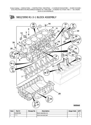
CASE WX210 Industry TIER 3 Wheeled Excavator Service Repair Manual Instant Download
Please open the website below to get the complete manualnn//
Download Presentation

Please find below an Image/Link to download the presentation.
The content on the website is provided AS IS for your information and personal use only. It may not be sold, licensed, or shared on other websites without obtaining consent from the author. Download presentation by click this link. If you encounter any issues during the download, it is possible that the publisher has removed the file from their server.
E N D
Presentation Transcript
Service manual WX210 WX240 WX210 WX240 TIER 3 WX210 Industry WX240 Industry WX210 Industry WX240 Industry TIER 3 Service manual Print No. 87677489A Print No. 87677489A
SAFETY INSTRUCTION This warning symbol points out important messages involving your safety. The non compliance with the warning preceded by the above mentioned key-words (WARNING and DANGER) can cause serious accidents or even the death of the persons involved. S Carefully read the safety rules contained herein and follow advised precautions to avoid potential haz- ards and to safeguard your safety and personal in- tegrity. Moreover in the present Manual have been given some instructions with texts in italics, preceded by the words NOTE and CAUTION: In this manual you will find this symbol together with the following key-words: NOTE: it emphasizes and underlines to the operator the correct technique or correct procedure to follow. S WARNING This symbol warns about the possibility of potential damages to the machine that can involve the oper- ator s safety. S CAUTION It warns the operator of a possible hazard of ma- chine damage in case he does not follow a deter- mined procedure. S DANGER With specific warnings about potential dangers for the operator s or other persons integrity directly or indirectly involved.
INDEX SECTION 01 - SAFETY PRECAUTIONS 1. GENERAL SAFETY INSTRUCTIONS.......................................................................................................... 2 2. USE INSTRUCTION................................................................................................................................... 11 SECTION 02 - CONTROLS AND INSTRUMENTS 1. SWITCHES AND PUSH-BUTTONS............................................................................................................. 1 2. CONTROLS AND PEDALS ........................................................................................................................ 13 3. MULTI-FUNCTION DISPLAY ..................................................................................................................... 16 SECTION 03 - TECHNICAL SPECIFICATIONS 1. MAIN COMPONENTS .................................................................................................................................. 1 2. DIMENSIONS - OPERATING WEIGHTS..................................................................................................... 4 3. DIGGING PERFORMANCE ....................................................................................................................... 10 4. LIFTING CAPACITIES................................................................................................................................ 20 5. HYDRAULIC SYSTEM ............................................................................................................................... 33 6. ROTATION ................................................................................................................................................. 34 7. TRAVEL...................................................................................................................................................... 35 7.1 TYRES................................................................................................................................................. 36 8. BRAKES ..................................................................................................................................................... 36 9. STEERING.................................................................................................................................................. 36 10. ELECTRICAL SYSTEM............................................................................................................................ 37 11. BUCKETS................................................................................................................................................. 37 12. TIGHTENING TORQUES......................................................................................................................... 38 13. CENTRALIZED LUBRICATION PUMP (OPTIONAL)............................................................................... 38 14. FUEL SYSTEM......................................................................................................................................... 38 15. ENGINE .................................................................................................................................................... 39 16. SUPPLY SUMMARIZING CHART............................................................................................................ 40 SECTION 04 - UPPER STRUCTURE 1. MAIN COMPONENTS .................................................................................................................................. 1 2. SLEWING BEARING .................................................................................................................................... 3 3. ROTATION GEARMOTOR........................................................................................................................... 7 3.1 DISASSEMBLY AND ASSEMBLY....................................................................................................... 12 4. MULTI-COOLER......................................................................................................................................... 13 4.1 TECHNICAL SPECIFICATIONS.......................................................................................................... 14 5. HYDRAULIC PUMPS ................................................................................................................................. 17 6. MUFFLER................................................................................................................................................... 18
https://www.ebooklibonline.com Hello dear friend! Thank you very much for reading. Enter the link into your browser. The full manual is available for immediate download. https://www.ebooklibonline.com
7. HYDRAULIC OIL TANK.............................................................................................................................. 19 8. AIR FILTER................................................................................................................................................. 25 9. COUNTERWEIGHT.................................................................................................................................... 25 10. FUEL SYSTEM......................................................................................................................................... 26 11. CAB AND OPERATOR S SEAT ............................................................................................................... 32 11.1 CAB AT VARIABLE HEIGHT (WX 210 Industry - WX 240 Industry)................................................. 43 12. CENTRALIZED LUBRICATION PUMP..................................................................................................... 44 SECTION 05 - UNDERCARRIAGE 1. UNDERCARRIAGE COMPONENTS............................................................................................................ 1 2. REAR RIGID AXLE....................................................................................................................................... 2 2.1 TECHNICAL SPECIFICATIONS............................................................................................................ 3 2.2 DISASSEMBLY AND ASSEMBLY......................................................................................................... 6 2.3 DISASSEMBLY AND ASSEMBLY......................................................................................................... 8 2.4 TROUBLESHOOTING......................................................................................................................... 87 2.5 SPECIAL TOOLS................................................................................................................................. 89 3. TRAVEL MOTOR........................................................................................................................................ 90 3.1 TECHNICAL SPECIFICATIONS.......................................................................................................... 90 3.2 DISASSEMBLY AND ASSEMBLY....................................................................................................... 91 3.3 DISASSEMBLY AND ASSEMBLY....................................................................................................... 92 4. CARDAN SHAFT...................................................................................................................................... 103 4.1 DISASSEMBLY AND ASSEMBLY..................................................................................................... 104 5. FRONT STEERING AXLE ........................................................................................................................ 106 5.1 TECHNICAL SPECIFICATIONS........................................................................................................ 107 5.2 DISASSEMBLY AND ASSEMBLY..................................................................................................... 110 5.3 DISASSEMBLY AND ASSEMBLY..................................................................................................... 112 5.4 TROUBLESHOOTING....................................................................................................................... 184 5.5 SPECIAL TOOLS............................................................................................................................... 186 6. WHEELS AND TYRES ............................................................................................................................. 187 7. BLADE ...................................................................................................................................................... 192 7.1 BLADE CYLINDER............................................................................................................................ 194 8. AXLE FLOATING LOCKING CYLINDERS ............................................................................................... 202 8.1 TECHNICAL SPECIFICATIONS........................................................................................................ 203 8.2 DISASSEMBLY AND ASSEMBLY..................................................................................................... 204 8.3 AIR BLEEDING.................................................................................................................................. 205 8.4 DISASSEMBLY AND ASSEMBLY..................................................................................................... 206 8.5 TROUBLESHOOTING....................................................................................................................... 208 9. STABILIZERS........................................................................................................................................... 209 9.1 STABILIZER CYLINDERS................................................................................................................. 212 9.2 TROUBLESHOOTING....................................................................................................................... 222 10. LEFT LADDER........................................................................................................................................ 224 11. RIGHT LADDER AND TOOL STORAGE BOX....................................................................................... 225 12. ROTARY CONTROL VALVE AND ELECTRIC ROTOR......................................................................... 226 12.1 TECHNICAL SPECIFICATIONS...................................................................................................... 226 12.2 DISASSEMBLY AND ASSEMBLY................................................................................................... 227 12.3 DISASSEMBLY AND ASSEMBLY................................................................................................... 228 12.4 ELECTRIC ROTOR ......................................................................................................................... 230
SECTION 06 - FRONT ATTACHMENT 1. TYPES OF FRONT ATTACHMENT ............................................................................................................. 2 2. HYDRAULIC CYLINDERS............................................................................................................................ 4 2.1 BOOM CYLINDER................................................................................................................................. 6 2.2 DIPPER CYLINDER (WX 210 - WX 240)............................................................................................ 16 2.3 DIPPER CYLINDER (WX 210 Industry - WX 240 Industry)................................................................. 26 2.4 SPECIAL TOOLS................................................................................................................................. 55 3. BUCKETS WX 210 - WX 240 ..................................................................................................................... 56 4. WX 210 - WX 240 QUICK COUPLER ........................................................................................................ 60 5. CLAMSHELL BUCKET............................................................................................................................... 64 SECTION 07 - STEERING SYSTEM 1. OPERATION................................................................................................................................................. 1 2. POWER STEERING..................................................................................................................................... 3 2.1 DISASSEMBLY AND ASSEMBLY......................................................................................................... 5 3. PRIORITY VALVE ...................................................................................................................................... 23 4. TROUBLESHOOTING................................................................................................................................ 24 SECTION 08 - BRAKE SYSTEM 1. OPERATION................................................................................................................................................. 1 2. SERVICE BRAKE......................................................................................................................................... 4 3. PARKING BRAKE......................................................................................................................................... 7 4. PEDAL BRAKE VALVE ................................................................................................................................ 8 5. ACCUMULATORS........................................................................................................................................ 9 6. TROUBLESHOOTING................................................................................................................................ 11 SECTION 09 - HYDRAULIC SYSTEM 1. HYDRAULIC SYSTEM ................................................................................................................................. 1 2. HYDRAULIC SYSTEM DIAGRAMS ............................................................................................................. 5 2.1 HYDRAULIC SYSTEM DIAGRAMS - UPPER STRUCTURE ............................................................... 5 2.2 HYDRAULIC SYSTEM DIAGRAMS - UNDERCARRIAGE ................................................................. 21 2.3 HYDRAULIC SYSTEM DIAGRAMS BLADE AND/OR STABILIZERS ................................................ 25 3. HYDRAULIC PUMPS ................................................................................................................................. 28 4. UPPER STRUCTURE CONTROL VALVE ................................................................................................. 48 5. UNDERCARRIAGE CONTROL VALVE ..................................................................................................... 60 6. PILOT CONTROL ASSY ............................................................................................................................ 62 7. ROTATION SYSTEM.................................................................................................................................. 71 8. TRAVEL...................................................................................................................................................... 75 9. STABILIZATION HYDRAULIC SYSTEM.................................................................................................... 87 10. BOOM HYDRAULIC SYSTEM ................................................................................................................. 93 11. HYDRAULIC SYSTEM ........................................................................................................................... 100
12. HYDRAULIC SYSTEM OF DIPPER ....................................................................................................... 106 13. HYDRAULIC SYSTEM OF PLACING BOOM......................................................................................... 110 14. HYDRAULIC SYSTEM WITH COMBINATION OF DIFFERENT FUNCTIONS (BOOM, PLACING BOOM, DIPPER AND BUCKET) ............................................................................. 117 15. HYDRAULIC SYSTEM OF HAMMER (WITH PLACING BOOM) ........................................................... 119 16. HYDRAULIC SYSTEM OF HAMMER AND SHEARS (WITH PLACING BOOM)................................... 122 17. HYDRAULIC SYSTEM OF SHEARS (WITH PLACING BOOM) ............................................................ 127 18. HYDRAULIC SYSTEM OF HAMMER (WITH MONOBOOM)................................................................. 130 19. HYDRAULIC SYSTEM OF HAMMER AND SHEARS (WITH MONOBOOM) ........................................ 133 20. HYDRAULIC SYSTEM OF SHEARS (WITH MONOBOOM).................................................................. 138 21. TROUBLESHOOTING............................................................................................................................ 141 SECTION 10 - ELECTRICAL SYSTEM 1. ELECTRICAL DIAGRAMS............................................................................................................................ 1 1.1 WX 210 - WX 240 .................................................................................................................................. 1 1.2 WX 210 Industry - WX 240 Industry..................................................................................................... 41 2. FUSES........................................................................................................................................................ 80 3. BATTERIES ................................................................................................................................................ 83 4. BULBS ........................................................................................................................................................ 87 5. TROUBLESHOOTING................................................................................................................................ 91 SECTION 11 - ELECTRONICS 1. MAIN COMPONENTS .................................................................................................................................. 1 1.1 ELECTRICAL POWER SUPPLY DIAGRAM ......................................................................................... 3 2. COMPONENTS OF LINE 1 .......................................................................................................................... 6 3. COMPONENTS OF LINE 2 ........................................................................................................................ 10 3.1 TRAVEL PEDAL .................................................................................................................................. 16 3.2 ATTACHMENT PEDAL (PLACING BOOM AND HAMMER)............................................................... 17 3.3 ELECTRO-HYDRAULIC SYSTEM ...................................................................................................... 18 3.4 POWER CONTROL SYSTEM............................................................................................................. 19 4. ENGINE SPEED ACTUATOR .................................................................................................................... 26 5. COOLANT TEMPERATURE DETECTION................................................................................................. 27 6. CHARGE AIR TEMPERATURE DETECTION............................................................................................28 7. HYDRAULIC OIL TEMPERATURE DETECTION....................................................................................... 29 8. PROPORTIONAL VALVE - FAN MOTOR .................................................................................................. 30 9. PROPORTIONAL VALVES - CONTROL BLOCK....................................................................................... 31 SECTION 12 - CALIBRATION 1. NECESSARY OPERATIONS BEFORE CALIBRATION............................................................................... 1 2. DISPLAY: CALIBRATION MENU ................................................................................................................. 3
3. CALIBRATIONS WITH THE ENGINE RUNNING......................................................................................... 4 3.1 VDO CALIBRATION.............................................................................................................................. 6 3.2 POWER CALIBRATION ........................................................................................................................ 8 3.3 MAIN VALVE CALIBRATION (CONTROL VALVE)............................................................................. 10 3.4 TRAVEL CALIBRATION...................................................................................................................... 13 3.5 PUMP DELIVERY CALIBRATION....................................................................................................... 15 3.6 ROTATION PUMP CALIBRATION...................................................................................................... 18 3.7 AUXILIARY PRESSURE CALIBRATION ............................................................................................ 20 4. CALIBRATIONS WITH THE ENGINE STOPPED ...................................................................................... 22 4.1 CALIBRATIONS, ALL SOLENOID VALVES, MAIN PUMP, ROTATION PUMP, AUXILIARY PRESSURE...................................................................................................................... 24 4.2 MAIN VALVE CALIBRATION (CONTROL VALVE)............................................................................. 26
SECTION 01 - SAFETY PRECAUTIONS 1. GENERAL SAFETY INSTRUCTIONS.......................................................................................................... 2 2. USE INSTRUCTION................................................................................................................................... 11
SECTION 01 - SAFETY PRECAUTIONS 1 Carefully read the safety rules contained herein and follow advised precautions to avoid potential haz- ards and to safeguard your safety and personal in- tegrity. In this manual you will find the following indications: S WARNING This symbol warns about the possibility of potential damages to the machine that can involve the opera- tor s safety. S DANGER With specific warnings about potential dangers for the operator s or other persons integrity directly or in- directly involved. The non compliance with the warning preceded by the above mentioned key-words (WARNING and DANGER) can cause serious accidents or even the death of the persons involved. Moreover in the present Manual have been given some instructions with texts in italics, preceded by the words NOTE and CAUTION, with following meanings for machine protection: NOTE: it emphasizes and underlines to the operator the correct technique or correct procedure to follow. S WARNING It warns the operator of a possible hazard of machine damage in case he does not follow a determined pro- cedure. Your safety and that of people around you depends on you. It is essential that you understand this man- ual for the correct operation, inspection, lubrication and maintenance of this machine.
2 SECTION 01 - SAFETY PRECAUTIONS 1. GENERAL SAFETY INSTRUCTIONS Carefully read this Manual before proceeding with maintenance, repairs, refuelling or other machine operations. Repairs have to be carried out only by authorized and instructed staff; specific precautions have to be taken when grinding, welding or when using mallets or heavy hammers. Not authorized persons are not allowed to repair or carry out maintenance on this machine. Do not carry out any work on the equipment without prior authori- zation. Ask your employer about the safety instructions in force and safety equipment. Nobody is allowed to seat on the operator s place during machine maintenance unless he is a qualified operator helping with the maintenance work. If it is necessary to move the equipment to carry out repairs or maintenance, do not lift or lower the equip- ment from any other position than the operator s seat. Never carry out any operation on the machine when the engine is running, except when specifically indi- cated. Stop the engine and ensure that all pressure is re- lieved from hydraulic circuits before removing caps, covers, valves, etc. All repair and maintenance operations should be carried out with the greatest care and attention. Service stairs and platforms used in a workshop or in the field should be built in compliance with the safety rules in force. Any functional disorders, especially those affecting the safety of the machine, should therefore be recti- fied immediately.
SECTION 01 - SAFETY PRECAUTIONS 3 1.1 EMERGENCY Be prepared for emergencies. Always keep at dis- posal on the machine a first aid kit and a fire extin- guisher. Make sure that the fire extinguisher is serviced in accordance with the manufacturer s in- structions. 1.2 EQUIPMENT Wear close fitting clothing and safety equipment ap- propriate for the job: Z safety helmet; Z safety shoes; Z heavy gloves; Z reflective clothing; Z wet weather clothing. If environment condition require it following personal safety equipment should be at hand: Z respirators (or dustproof masks); Z ear plugs or acoustic ears protections; Z goggles with lateral shield or masks for eyes pro- tection. Do not wear rings, wristwatches, jewels, unbuttoned or flapping clothing such as ties, torn clothes, scarves, open jackets or shirts with open zips which could get caught into moving parts.
4 SECTION 01 - SAFETY PRECAUTIONS 1.3 ENGINE - RADIATOR Never leave the engine run in closed spaces without ventilation and not able to evacuate toxic exhaust gases. Keep the exhaust manifold and tube free from combustion materials. Do not refuel with the engine running, especially if hot, as this increases fire hazard in case of fuel spill- age. Never attempt to check or adjust the fan belts when the engine is running. Never lubricate the machine with the engine run- ning. Pay attention to rotary pieces and do not allow to an- yone to approach to avoid becoming entangled. If hands, clothes or tools get caught in the fan blades or in the transmission belt, this can cause amputa- tions, violent tears and generate condition of serious danger; for this reason avoid touching or to come close to all rotary or moving parts. A violent jet of the coolant from the radiator can cause damages and scalds. If you are to check the coolant level, you have to shut off the engine previously and to let cool down the ra- diator and its pipes. Slowly unscrew the cap to re- lease the inside pressure. If necessary, remove the cap with hot engine, wear safety clothes and equipment, then loosen the cap slowly to relieve the pressure gradually. When checking the fuel, oil and coolant levels, use exclusively explosion proof classified lamps. If this kind of lamps are not used fires or explosions may occur.
SECTION 01 - SAFETY PRECAUTIONS 5 1.4 HYDRAULIC SYSTEMS Splashes of fluids under pressure can penetrate the skin causing serious injuries. Avoid this hazard by relieving pressure before dis- connecting hydraulic or other lines. Relieve the residual pressure by moving the hydrau- lic control levers several times. Tighten all connections before applying pressure. To protect the eyes wear a facial shield or safety goggles. Protect your hands and body from possible splashes of fluids under pressure. Swallowing hydraulic oil is a severe health hazard. When hydraulic oil has been swallowed, avoid vom- iting, but consult a doctor or go to a hospital. If an accident occurs, see a doctor familiar with this type of injury immediately. Any fluid penetrating the skin must be removed with- in few hours to avoid serious infections. Flammable splashes may originate because of the heat near pipes with fluids under pressure, with the result of serious scalds for the persons hit. Do not weld or use torches near pipes containing fluids or other flammable materials. Pipes under pressure can accidentally be pierced when the heat expands beyond the area immediate- ly heated. Arrange for fire resistant temporary shields to pro- tect hoses or other components during welding. Have any visible leakage repaired immediately. Escaping oil pollutes the environment. Soak up any oil that has escaped with a proper binding agent. Sweep up binding agent and dispose of it separately from other waste. Never search for leakages with the fingers, but use a piece of cardboard and always wear goggles. Never repair damaged piping; always replace it. Re- place hydraulic hoses immediately on detecting any damage or moist areas. Always store hydraulic oil in the original containers.
6 SECTION 01 - SAFETY PRECAUTIONS HOSES AND TUBES Always replace hoses and tubes if the cone end or the end connections on the hose are damaged. When installing a new hose, loosely connect each end and make sure the hose takes up the correct po- sition before tightening the connections. Clamps should be tightened sufficiently to hold the hose with- out crushing and to prevent chafing. After hose replacement to a moving component, check that the hose does not foul by moving the component through the complete range of travel. Be sure any hose which has been installed is not kinked or twisted. Hose connections which are damaged, dented, crushed or leaking, restrict oil flow and the productiv- ity of the components being served. Connectors which show signs of movement from the original po- sition have failed and will ultimately separate com- pletely. A hose with a frayed outer sheath will allow the water penetration. Concealed corrosion of the wire rein- forcement will subsequently occur along the hose length with resultant hose failure. Ballooning of the hose indicates an internal leakage due to structural failure. This condition rapidly deteri- orates and total hose failure soon occurs. Kinked, crushed, stretched or deformed hoses gen- erally suffer internal structural damage which can re- sult in oil restriction, a reduction in the speed of operation and ultimate hose failure. Free-moving, unsupported hoses must never be al- lowed to touch each other or related working surfac- es. This causes chafing which reduces hose life. O-RINGS Replace O-rings, seal rings and gaskets whenever they are disassembled. Never mix new and old seals or O-rings, regardless of condition. Always lubricate new seal rings and O- rings with hydraulic oil before installation to relevant seats. This will prevent the O-rings from rolling over and twisting during mounting which will jeopardize seal- ing.
SECTION 04 - UPPER STRUCTURE 1 1. MAIN COMPONENTS WX 210 - WX 240 1. Slewing bearing 2. Rotation gearmotor 3. Multi-cooler 4. Diesel engine 5. Muffler 6. Hydraulic pumps 7. Hydraulic oil tank 8. Air filter 9. Counterweight 10. Fuel tank 11. Cab and operator s seat
2 SECTION 04 - UPPER STRUCTURE WX 210 Industry - WX 240 Industry 1. Slewing bearing 2. Rotation gearmotor 3. Multi-cooler 4. Diesel engine 5. Muffler 6. Hydraulic pumps 7. Hydraulic oil tank 8. Air filter 9. Counterweight 10. Fuel tank 11. Cab and operator s seat 12. Cab raising device
SECTION 04 - UPPER STRUCTURE 3 2. SLEWING BEARING The slewing bearing consists of an external ring inte- gral to the upper structure, an internal ring integral to the undercarriage and a single series of balls. The pinion of the rotation gearbox, controlled by the rotation motor by means of the gears of the gearbox itself, rotates around its own axis and makes a revo- lution around the centre of the internal ring of the slewing bearing, thus enabling the upper structure to rotate independently from the undercarriage. TECHNICAL SPECIFICATIONS Teeth Module.................................................................10 Number of teeth.................................................110 Pressure angle...................................................25
4 SECTION 04 - UPPER STRUCTURE DISASSEMBLY Park the machine on a level and firm surface. Lower the attachment to the ground. Lower the blade and the stabilizers to the ground. Engage the parking brake. Lock the upper structure. Stop the engine. Place some wedges under the wheels so as to pre- vent the machine from moving. Move both hydraulic control levers in all directions, to release possible residual pressure inside the hy- draulic system. For slewing bearing disassembly, it is necessary to remove the upper structure. Disconnect all hydraulic hoses and electric harness- es from the rotary control valve and from the rotor. Close all openings on pipes and rotary control valve with plugs in order to prevent dirt from entering. By using chains or ropes (with a carrying capacity of 20000 kg (44000 lb)), sling the upper structure in its front and rear part. Hook these ropes to two cranes (with a lifting capac- ity of ~ 20000 kg (44000 lb) each) and slowly tension them without lifting the upper structure. Please remember that the internal ring (1) of the slewing bearing is fastened to the undercarriage and that the external ring (2) is fastened to the upper structure. Loosen and remove the screws (3) from the slewing bearing s external ring (2). Keep the spacers (5) be- cause they will be reused. Now the upper structure is detached from the under- carriage. Carefully lift the upper structure, until the pinion of the rotation gearbox is freed. Turn the upper struc- ture away from the undercarriage. Using a hoist, hook the slewing bearing (7). For this operation, insert 3 threaded eyebolts (8), staggered by 120 , into the holes, fastening them with the nuts (9). Loosen and remove the screws (4) and keep the spacers (6) as they will be reused. Lift the slewing bearing (7) and remove it from the undercarriage.
SECTION 04 - UPPER STRUCTURE 5 ASSEMBLY When the slewing bearing is new, eliminate the anti- corrosive protection coat. Carefully clean all supporting surfaces of the under- carriage and the upper structure. The metal of the supporting surfaces must be bright, clean and de- greased. Eliminate projections and burrs. Clean the holes of the undercarriage. Carefully clean the threaded holes of the upper structure and check the threads. If damaged, pass them again with the screw tap. Apply the adhesive to the supporting surface of the undercarriage. For this operation, use a painting roll- er, a hard brush or a plastic spatula. Do not let the adhesive enter the holes. Adhesive on threads causes higher friction and, therefore, an al- teration of the tightening torque. Hook the new slewing bearing to the hoist. Rotate the internal and the external ring so that the mark (S) on the external ring is at 90 to the travel di- rection, and the mark (S) on the internal ring is on the opposite side.
6 SECTION 04 - UPPER STRUCTURE Rotate the slewing bearing on the undercarriage and leave it hanging above the supporting surface, with- out resting it. As a guide, screw in at least three new screws (4) with relevant spacers (6). Carefully rest the slewing bearing and disconnect the hoist from the slewing bearing. Screw in all remaining new screws with the relevant spacers and cross-tighten them using a torque wrench. Tightening torque: 280 Nm (206.52 lbf ft) Mark the screws (4) already tightened. Apply the adhesive, as described, also to the sup- porting surface of the upper structure. Apply grease in a level coat to the teeth of the slew- ing bearing, so that the gaps between the teeth are completely filled. Rotate the upper structure on the undercarriage and leave it hanging above the slewing bearing without resting it. Carefully continue lowering the upper structure, in- serting the pinion between the teeth. As a guide, screw in at least three new screws (3) with relevant spacers (5). Carefully release the upper structure. Screw in all remaining new screws (3) with the rele- vant spacers (5) and cross-tighten them using a torque wrench. Tightening torque: 280 Nm (206.52 lbf ft) Mark the screws (3) already tightened. Connect all hydraulic hoses and electric harnesses again to the rotary control valve and to the rotor. Remove the ropes from the upper structure. Fill and bleed air from the hydraulic system. Operate the machine and check all hydraulic hoses for tight- ness. The adhesive between the slewing bearing and the upper structure and between the slewing bearing and the undercarriage increases the load capacity of the screwed connection and contemporarily serves as a seal between the gaps. The adhesive hardens when exposed to air. A definitive rigidity is obtained after ca. six hours. Fully load the machine only after this time has elapsed.
SECTION 04 - UPPER STRUCTURE 7 3. ROTATION GEARMOTOR The rotation device consists of an hydraulic motor (1) and a gearbox (2). The hydraulic motor consists of an axial-piston motor. The gearbox is used to ro- tate the upper structure by means of the coupling of the relevant pinion (3) with the internal teeth of the slewing bearing. The rotation device is installed on the main frame of the upper structure. 3.1 TECHNICAL SPECIFICATIONS DIMENSIONS
8 SECTION 04 - UPPER STRUCTURE DATA WX 210 WX 240 Model MT706T056 MT706T057 Total ratio 24.5 kg (lb) 140 (308) Dry weight litres (gal) 6 Oil capacity (1.60) Engine A2FM56 A2FM63 bar (psi) 370 (5364) Differential maximum pressure kNm (lbs ft) Output torque 8076 () 9086 () bar (psi) 12.5 (181) Opening pressure bar (psi) 50 Maximum operating pressure (725) Brake yes Nm (lbf ft) 475 Maximum braking torque (350.34) LUBRICATION The gearmotor has two screw plugs (1) and (2) for oil filling and a plug (3) to be unscrewed for draining.
SECTION 04 - UPPER STRUCTURE 9 TIGHTENING TORQUES
10 SECTION 04 - UPPER STRUCTURE 3.2 DISASSEMBLY AND ASSEMBLY DISASSEMBLY Park the machine on a level and firm surface. Lower the attachment to the ground. Lower the blade and the stabilizers to the ground. Engage the parking brake. Lock the upper structure. Stop the engine. Move both hydraulic control levers in all directions, to release possible residual pressure inside the hy- draulic system. Disconnect the pilot control. Place some wedges under the wheels so as to pre- vent the machine from moving. Mark and disconnect the hydraulic lines (2) and re- move the speed sensor (3) from the slewing gearbox (1). Close all openings on hoses and rotation gearbox with plugs in order to prevent dirt from entering. Using ropes, hook the slewing bearing (1) by means of eyebolts (5) and connect to a crane. Mark the position of the rotation gearbox. Unscrew and remove the screws (4). Using the crane, lift and remove the slewing bearing (1). The slewing bearing is glued to the supporting sur- face. To detach the glue, slightly hit the borders of the flange with a hammer.
SECTION 04 - UPPER STRUCTURE 11 ASSEMBLY Using a solvent, accurately clean the supporting sur- faces of the rotation gearbox and of the upper struc- ture s frame from paint and grease. Then check for possible damage. The metal of the supporting surfaces must be bright, clean and degreased. Apply an adhesive strip with a thickness of approxi- mately 1 mm (0.04 in) in the form of a ring around the hole of each fastening screw. The adhesive must be applied at a certain distance from the holes, in order to prevent that, when cou- pling the two surfaces, the adhesive enters the threaded holes. The adhesive must only be applied when the gearbox is ready to be installed. Using the ropes connected to the eyebolts (5), hook the gearbox to the crane, bring it to mounting posi- tion and rest it without moving it. Screw in the screws (4) and cross-tighten them, marking the screws already tightened. Tightening torque: 250 Nm (184.39 lbf ft) Assemble speed sensor (3). Connect the hydraulic lines (2) and fill oil into the gearbox. Bleed air from the hydraulic system.
12 SECTION 04 - UPPER STRUCTURE 3.3 DISASSEMBLY AND ASSEMBLY 1. Rotation motor 2. Screw 3. Screw 4. O-ring 5. Screw 6. Washer 7. Flange 8. Brake discs 9. O-ring 10. Back-up ring 11. O-ring 12. Back-up ring 13. Piston 14. Spring 15. Ring 16. Snap ring 17. Gear 18. Planetary gears assy 19. Planetary gears assy 20. O-ring 21. Ring gear 22. O-ring 23. Spacer 24. Ring nut 25. Shim 26. Bearing 27. Seal ring 28. Gearbox body 29. Plug 30. Bearing 31. Ring 32. Shim 33. Pinion 34. Cross pin
SECTION 04 - UPPER STRUCTURE 13 4. MULTI-COOLER The multi-cooler consists of three radiator cores. The front radiator, in travel direction, is passed through by the return oil of the working hydraulics, the rear radiator by the coolant of the diesel engine, while the upper radiator is passed through by the air of the turbocharger. The fan is actuated by a geared motor with adjustable speed. Speed adjustment is managed by the load-limit regulator, according to temperature. With low temperatures, the fan rotates slowly; this keeps the noise level low and contempo- rarily reduces power demand to the minimum. A low temperature forces the load-limit regulator to send a high current to the proportional valve. By means of the electric force, the control piston is opened further, and therefore a bypass is created, through which the oil, passing in front of the motor, drains into the channel of tank T. In this way, a low fan speed is set. When temperature increases, the load-limit regula- tor reduces current on the proportional valve. The control piston is less opened, and therefore the mo- tor receives a higher oil delivery. The fan speed in- creases. The cooling air flow is sucked by the fan in the mid- dle of the excavator, conveyed through the multi- cooler and then directed outside through the slots in the panelling. A pressure relief valve, integrated in the proportion- al valve, protects the fan system against possible pressure peaks. The geared motor receives on connection P the pressurized oil coming from the brake and steering systems. There is pressurized oil also on the mo- tor s closing plate, where an electronic proportional valve connected in parallel is located, with a bypass function. When the motor is stopped, a replenishing valve guarantees oil delivery to the motor during the fan deceleration phase, until it comes to a complete stop. In case of anomalies, e.g. in case a cable breaks, the proportional valve receives no current. There- fore, the fan rotates at its maximum speed. In this case, the pressure in the fan system is limited by the pressure relief valve. The load-limit regulator analyses three signals it constantly receives from the temperature sensor of the coolant, from the temperature sensor of the tur- bocharger air and from the temperature sensor of the hydraulic oil. The highest of these three values is taken into consideration for proportional valve ad- justment.
14 SECTION 04 - UPPER STRUCTURE 4.1 TECHNICAL SPECIFICATIONS WX 210 WX 240 Oil mass A x B x C mm (in) 835 x 500 x 100 (32.87 x 19.68 x 3.94) H2O D x E x F mass mm (in) 835 x 382 x 100 (32.87 x 15.04 x 3.94) G x H x I Aftercooler mass mm (in) 795 x 202 x 113 (31.3 x 7.95 x 4.45) L. Height mm (in) 997 5 (39.25 0.19) M. Width mm (in) 1000 5 (39.37 0.19) N. Thickness mm (in) 354 3 (13.93 0.12) dm2 (in)2 Aftercooler radiating surface 16 (248) H2O radiating surface dm2 (in)2 31 (480) dm2 (in)2 Oil radiating surface 41.8 (648) Aftercooler service pressure bar (psi) 2.5 (36) H2O service pressure bar (psi) 1 (15) Oil service pressure bar (psi) 16 (232) Weight kg (lb) 130 (286)
SECTION 04 - UPPER STRUCTURE 15 4.2 COOLANT LEVEL, TOP-UP AND CHANGE LEVEL CHECK The coolant level must be checked daily, so as to de- tect in time liquid leaks and prevent damage. Shut off the engine and wait until the engine and the cooling system reach 50 C (122 F). Open the engine compartment cover. The coolant level must be between notches min and max of the surge tank (1). If necessary, top up the coolant. To perform this operation, open with caution the cap (2) of the surge tank of about half of a turn, to allow the pressure to relieve from the cooling system. Only after pressure relief can you completely un- screw the plug (2) and top up the coolant. Retighten the plug. Close the engine compartment cover. TOP-UP The coolant must consists in a mixture of 50% of dis- tilled water and 50% of antifreeze. Before performing any top up or additive change, ask the After-sales Service about the specifications of the required additive allowed for your machine. First of all mix the components in a clean container and then pour the mixture into the cooling system. If the mixture components are poured into the cooling system one after the other, it is not possible to obtain the correct mixture ratio. There is also the possibility that components do not mix together in the correct way. NOTE: do not use not authorized additives. The cor- rosion produced by this improper use, can cause leaks in the cooling system and serious damages to the engine.
16 SECTION 04 - UPPER STRUCTURE GEAR BOX Park the machine on a level and firm surface. Lower the working attachment to the ground. Activate the parking brake. Place the machine in a safe condition. Stop the engine. Open the cover of the engine compartment and the door in front of the multi-cooler. Prepare a collecting container for the coolant. Unscrew plug (1) of expansion tank (2). Using the oil drain hose, which must be clean, drain the coolant from the cooler. The drain sleeve (3) of the cooler coolant can be ac- cessed from the front, on the left. Collect the coolant in the previously prepared con- tainer. Fill the new liquid inside of the expansion tank, until the level sets between references min and max . Tighten the plug (1) again. After a short test, check again the liquid level and, if necessary, top up.
SECTION 04 - UPPER STRUCTURE 17 5. HYDRAULIC PUMPS 1. Diesel engine 2. Flexible coupling 3. Variable-displacement twin pump 4. Rotation pump 5. Double gear pump The variable-displacement twin pump (3) is actuat- ed by the diesel engine (1) through a flexible cou- pling (2). The hydraulic tank provides cleaned and cooled oil to the pumps. The variable-displacement twin pump (3) sucks oil through the hydraulic hoses. The built- in pilot control pump sucks oil directly into the dou- ble pump s casing. The rotation pump (4) is flanged to the side of the twin pump (3). The auxiliary pump (supply pump), integrated into the rotation pump (4), sucks oil by means of a sep- arate hose. A twin gear pump (5) is installed on the diesel en- gine s (1) power take-off. The first pump is provided for the steering system, as well as for the fan motor. The second pump supplies the brake system and the clamshell rotation device. The double gear pump sucks oil from the tank through its own hose.
18 SECTION 04 - UPPER STRUCTURE 6. MUFFLER Gases produced during the internal combustion are conveyed to the muffler, which discharges them through the terminal located outside the machine. 1. Clevis 2. Muffler 3. Bracket 4. Screw 5. Washer 6. Screw 7. Nut 8. Washer 9. Nut 10. Washer 11. Collar 12. Screw 13. Washer 14. Screw 15. Collar 16. Sleeve 17. Screw 18. Clamp 19. Hose 20. Hose
Suggest: If the above button click is invalid. Please download this document first, and then click the above link to download the complete manual. Thank you so much for reading
SECTION 04 - UPPER STRUCTURE 19 7. HYDRAULIC OIL TANK The hydraulic tank (6) is used for hydraulic oil sup- ply. It contains the filter housing with the return fil- ter s seat (16). The breather valve with filter (1) preserves the purity of oil from environmental influences. A built-in dou- ble-acting valve (17) makes sure that, when the oil level in the tank reduces, the atmospheric pressure continues entering until the allowable pressure is reached. It also makes sure that the pressure in the tank is limited when volume variations occur due to oil heating or cylinder retraction. The cover (4), in the middle with the breather valve (1), closes the inspection opening. Several fittings for the return hoses to the filter hous- ing, for the return hoses under the filter housing as well as the fitting for the suction hose are welded to the outer side of the tank. The oil drain plug (10) is located at the bottom. The temperature sensor (7), detects the hydraulic temperature. In order to control temperature, the load-limit regulator receives the temperature signal in the form of electric resistance. The pressure switch (6) on the filter housing has the function to control the filter. If the filter element is clogged (16) and pressure reaches a non-allowable value, the contact closes. In this way, an optical and acoustic signal is generated. 1. Breather valve with filter 2. Screw 3. Washer 4. Cover 5. O-ring 6. Oil tank 7. Pressure switch 8. Level gauge 9. Temperature sensor 10. Oil drain plug 11. Screw 12. Washer 13. Cover 14. O-ring 15. Spring 16. Filter element 17. Valve 18. Seal ring
https://www.ebooklibonline.com Hello dear friend! Thank you very much for reading. Enter the link into your browser. The full manual is available for immediate download. https://www.ebooklibonline.com


