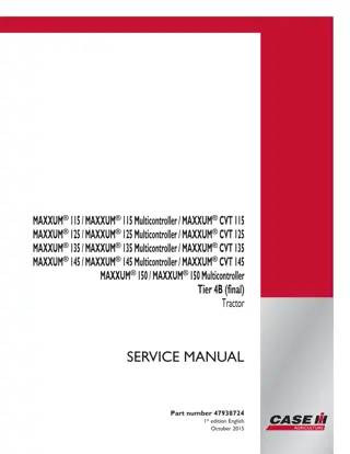
CASE IH PUMA 130 145 160 Tractor Service Repair Manual Instant Download
Please open the website below to get the complete manualnn// n
Download Presentation

Please find below an Image/Link to download the presentation.
The content on the website is provided AS IS for your information and personal use only. It may not be sold, licensed, or shared on other websites without obtaining consent from the author. Download presentation by click this link. If you encounter any issues during the download, it is possible that the publisher has removed the file from their server.
E N D
Presentation Transcript
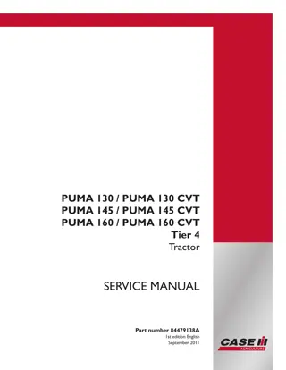
PUMA 130 / PUMA 130 CVT PUMA 145 / PUMA 145 CVT PUMA 160 / PUMA 160 CVT Tier 4 Tractor SERVICE MANUAL Part number 84479138A 1st edition English Printed in U.S.A. Copyright 2011 CNH America LLC. All Rights Reserved. Case IH is a registered trademark of CNH America LLC. Racine Wisconsin 53404 U.S.A. September 2011
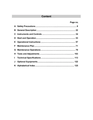
Contents INTRODUCTION HYDRAULIC, PNEUMATIC, ELECTRICAL, ELECTRONIC SYSTEMS A PRIMARY HYDRAULIC POWER SYSTEM.............................................. A.10.A PRIMARY HYDRAULIC POWER SYSTEM Closed center mechanical remote valve ... A.10.B PRIMARY HYDRAULIC POWER SYSTEM Electro-hydraulic remote valve............. A.10.C SECONDARY HYDRAULIC POWER SYSTEM.......................................... A.12.A HYDRAULIC COMMAND SYSTEM...................................................... A.14.A PNEUMATIC SYSTEM ................................................................... A.20.A ELECTRICAL POWER SYSTEM ........................................................ A.30.A ELECTRONIC SYSTEM ................................................................. A.50.A FAULT CODES ........................................................................... A.50.A ENGINE AND PTO IN................................................................... B ENGINE .................................................................................. B.10.A FUEL AND INJECTION SYSTEM........................................................ B.20.A AIR INTAKE SYSTEM.................................................................... B.30.A EXHAUST SYSTEM...................................................................... B.40.A EXHAUST SYSTEM Emissions control .................................................. B.40.B ENGINE COOLANT SYSTEM ........................................................... B.50.A TRANSMISSION, DRIVE AND PTO OUT........................................ C TRANSMISSION Semi-Powershift ....................................................... C.20.D TRANSMISSION Powershift ............................................................. C.20.E TRANSMISSION Continuously Variable Transmission (CVT) ........................... C.20.G ADDITIONAL REDUCERS Overdrive.................................................... C.30.D REAR PTO Mechanical .................................................................. C.40.B REAR PTO Hydraulic..................................................................... C.40.C FRONT PTO Hydraulic ................................................................... C.42.C AXLES, BRAKES AND STEERING................................................. D FRONT AXLE ............................................................................ D.10.A REAR AXLE .............................................................................. D.12.A 84479138A 06/06/2011
2WD-4WD SYSTEM Hydraulic........................................................... D.14.C STEERING Hydraulic..................................................................... D.20.C STEERING Autoguidance................................................................ D.20.E SERVICE BRAKE Hydraulic.............................................................. D.30.C SERVICE BRAKE Pneumatic ............................................................ D.30.E PARKING BRAKE Mechanical ........................................................... D.32.B PARKING BRAKE Electronic............................................................. D.32.D BRAKE CONNECTION Hydraulic........................................................ D.34.C SUSPENSION Hydraulic ................................................................. D.40.C WHEELS AND TRACKS Wheels......................................................... D.50.C FRAME AND CAB ........................................................................ E FRAME Primary frame ................................................................... E.10.B SHIELD................................................................................... E.20.A USER CONTROLS AND SEAT .......................................................... E.32.A USER PLATFORM ....................................................................... E.34.A ENVIRONMENT CONTROL Heating, ventilation and air-conditioning................... E.40.D HITCH AND WORKING TOOL....................................................... H HITCH Front hitch ........................................................................ H.10.B HITCH Rear hitch......................................................................... H.10.C HITCH Electronic draft control............................................................ H.10.D 84479138A 06/06/2011
https://www.ebooklibonline.com Hello dear friend! Thank you very much for reading. Enter the link into your browser. The full manual is available for immediate download. https://www.ebooklibonline.com
https://www.ebooklibonline.com Hello dear friend! Thank you very much for reading. Enter the link into your browser. The full manual is available for immediate download. https://www.ebooklibonline.com
HYDRAULIC, PNEUMATIC, ELECTRICAL, ELECTRONIC SYSTEMS - PRIMARY HYDRAULIC POWER SYSTEM 2 BAIL10CVT037AAB The gear pump (1) Figure 3 supplies low pressure and lubrication oil. 3 BAIL10CVT066AAB Located on the right hand side of the rear axle housing is a resounding filter assembly. 4 BAIL10CVT039AAB The priority valve (1) located on the top of the main pump diverts high pressure oil to the steering, the trailer brake valve (where fitted) (2) and high pressure circuit. (Refer to Priority valve - Dynamic description (A.14.A)) 5 BAIL10CVT041AAB Closed centre remote valves . 84479138A 06/06/2011 A.10.A / 19
HYDRAULIC, PNEUMATIC, ELECTRICAL, ELECTRONIC SYSTEMS - PRIMARY HYDRAULIC POWER SYSTEM There are two types of remote valves available for the closed centre system. Mechanical remote valves operated via a cable from within the cab or electro hydraulically operated valves, (1) Figure 6, which are operated by electrical switches and have their own in built processor to control oil flow via a solenoid valve. 6 BAIL10CVT038AAB Mechanical remote control valves (1) are also available with electronic draft control. (2). Mechanical remotes are also available with a combination configurable and non configurable valve slices . See Table 1 7 BRE1744B The hydraulic lift Electronic Draft Control valve (EDC valve) is a stack type proportional solenoid operated valve (1) mounted with the remote control valves at the rear of the tractor. (Refer to HITCH Electronic draft control - Static description (H.10.D) 8 BAIL10CCM010AAB Tractors installed with the electronic draft control hydraulic lift assembly use a unique operator control panel. 84479138A 06/06/2011 A.10.A / 20
Thank you so much for reading. Please click the Buy Now! button below to download the complete manual. After you pay. You can download the most perfect and complete manual in the world immediately. Our support email: ebooklibonline@outlook.com


