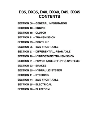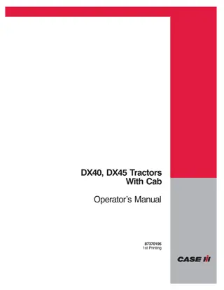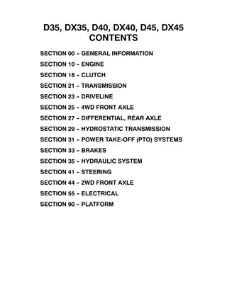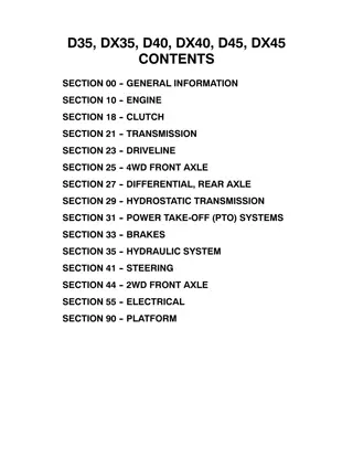
Case IH DX35 DX40 DX45 Tractors (Pin NumberHBA015001 and above) Operator’s Manual Instant Download (Publication No.87300519)
Please open the website below to get the complete manualnn//
Download Presentation

Please find below an Image/Link to download the presentation.
The content on the website is provided AS IS for your information and personal use only. It may not be sold, licensed, or shared on other websites without obtaining consent from the author. Download presentation by click this link. If you encounter any issues during the download, it is possible that the publisher has removed the file from their server.
E N D
Presentation Transcript
DX35, DX40, DX45 Tractors PIN Number HBA015001 and Above Operator s Manual 87300519
TO THE OWNER This manual contains information concerning the adjustment and maintenance of your Case IH Model DX35, DX40 and DX45 Tractors. You have purchased a dependable machine, but only by proper care and operation can you expect to receive the performance and long service built into this tractor. Please have all operators read this manual carefully and keep it available for ready reference. Your Case IH dealer will instruct you in the general operation of your tractor. (Refer to the Delivery Report at the back of this manual.) Your dealer s staff of factory-trained service technicians will be glad to answer any questions that may arise regarding the operation of your tractor. Your Case IH dealer carries a complete line of genuine Case IH service parts. These parts are manufactured and carefully inspected to insure high quality and accurate fitting of any necessary replacement parts. Be prepared to give your dealer the model and product identification number of the tractor, when ordering parts. Locate these numbers now and record them below. Refer to the General Information section of this manual for the location of the model and product identification numbers of your tractor. Model Product Identification Number 50036725 CAUTION Thissafetyalertsymbolindicatesimportantsafetymessages inthis manual.When yousee thissymbol, carefully read the message that follows and be alert to the possibility of personal injury or death. CAUTION Pictures in this manual may show protective shielding open or removed to better illustrate a particular feature or adjustment. Be certain, however, to close or replace all shielding before operating the machine. IMPROVEMENTS Case, LLC is continually striving to improve its products. We reserve the rightto makeimprovements orchanges when it becomes practical and possible to do so, without incurring any obligation to make changes or additions to the equipment sold previously. 0-1
CONTENTS SAFETY . . . . . . . . . . . . . . . . . . . . . . . . . . . . . . . . . . . . . . . . . . . . . . . . . . . . . . . . . . . . . . 0-7 GENERAL INFORMATION . . . . . . . . . . . . . . . . . . . . . . . . . . . . . . . . . . . . . . . . . . . . . 1-1 OPERATION . . . . . . . . . . . . . . . . . . . . . . . . . . . . . . . . . . . . . . . . . . . . . . . . . . . . . . . . . . 2-1 LUBRICATION AND MAINTENANCE . . . . . . . . . . . . . . . . . . . . . . . . . . . . . . . . . . . . 3-1 SPECIFICATIONS . . . . . . . . . . . . . . . . . . . . . . . . . . . . . . . . . . . . . . . . . . . . . . . . . . . . . 4-1 INDEX . . . . . . . . . . . . . . . . . . . . . . . . . . . . . . . . . . . . . . . . . . . . . . . . . . . . . . . . . . . . . . 4-13 DELIVERY REPORT . . . . . . . . . . . . . . . . . . . . . . . . . . . . . . . . . . . . . . . . . . . . . . . . . . 4-15 0-2
https://www.ebooklibonline.com Hello dear friend! Thank you very much for reading. Enter the link into your browser. The full manual is available for immediate download. https://www.ebooklibonline.com
FEDERAL EMISSIONS WARRANTY (California owner s emissions warranty is covered elsewhere) CaseIHwarrantsthatyournew1996andlaterheavy-duty off-roaddieselenginewas designed,built,andequippedtoconformtoapplicable U.S. Environmental Protection Agency regulations for a period of use of five years or 3,000 hours of operation, whichever occurs first. The new model year, class of diesel engine, and emission application determination for your engine are identified on the emission control informationlabelaffixedtothetopofyourengine srockerarmcover.Thewarrantyperiodbeginsonthedatethenewequipmentissoldtothe first retail purchaser. Anyemissioncontrolsystempartswhichareprovendefectiveduringnormalusewillberepairedorreplacedduringthewarranty period.The warrantyrepairsandservicewillbeperformedbyanyauthorizedCaseIHdealeratthedealer splaceofbusiness,withnochargeforpartsor labor (including diagnosis). As the engine owner, you are responsible to perform all the required maintenance listed in your owner s manual. Case IH will not deny an emission warranty claim solely because you have no record of maintenance; however, a claim may be denied if your failure to perform maintenance resulted in the failure of a warranted part. Receipts covering regular maintenance should be retainedin theevent ofquestions and these receipts should be passed on to each subsequent owner of the engine. ItisrecommendedreplacementpartsusedformaintenanceorrepairsbeCaseIHServicePartstomaintainthequalityoriginallydesignedinto your emission certified engine. The use of non-Case IH parts does not invalidate the warranty on other components unless the use of such parts causes damage to warranted parts. Case IH wishes to assure the emission control systems warranty is being properly administered. If you believe you have not received the service entitled to under this warranty, you should contact the nearest Case IH Branch Office for assistance. Please note that the Emission Warranty does not cover: 1. Systems and parts that were not first installed on the new equipment or engine as original equipment by Case IH. 2. Part malfunctions caused by abuse, misuse, improper adjustment, modification, alteration, tampering, disconnection, improper or inadequate maintenance, or use of non-recommended fuels and lubricating oils. 3. Accident caused damage, acts of nature, or other events beyond Case IH s control. 4. Replacement of expendable items made in connection with scheduled maintenance. 5. Parts requiring replacement, inspection or adjustment maintenance intervals for reasons other than being defective. 6. Parts which are not Case IH Service Parts. 7. Loss of time, inconvenience, loss of use of equipment/engine or commercial loss. 8. Equipment with altered or disconnected hourmeter where the hours cannot be determined. 9. Equipment normally operated outside the United States. 10. Non-defective parts replaced by other than Case IH dealers. Coverage This emission control system warranty applies to the following emission control parts. Fuel Injection Pump Fuel Injectors Turbocharger Intake Manifold Exhaust Manifold Boost Pressure Tubing-connection to Aneroid Device ON F.I.P. 0-3
CALIFORNIA EMISSION CONTROL WARRANTY STATEMENT Your Warranty Rights and Obligations TheCaliforniaAirResourcesBoardandCaseIHarepleasedtoexplaintheemissioncontrolsystemwarrantyonyourengine.InCalifornia,new 1997andlaterheavy-duty off-roadengines from100to150HPmustbedesigned,built,andequippedtomeettheState s stringentanti-smog standards. Case IH must warrant the emission control system on your engine for the periods of time listed below, provided therehas beenno abuse, neglect, or improper maintenance of your engine. Your emission control system includes parts such as the fuel injection system and the air induction system. Where a warrantable condition exists, Case IH will repair your heavy-duty off-road engine at no cost to you, including diagnosis, parts, and labor. Manufacturer s Warranty Coverage: The 1997 and later heavy-duty off-road engines are warranted from the original date of delivery for five years or 3,000 hours of operation, whichever occurs first. If any emission-related part on your engine is defective, the part will be repaired or replaced by Case IH. Owner s Warranty Responsibilities: As the heavy-duty off-road engine owner, you are responsible for the performance of the required maintenance listed in your owner s manual.CaseIHrecommendsthatyouretainallreceiptscoveringmaintenanceonyourheavy-dutyoff-roadengine,butCaseIHcannot deny warranty solely for the lack of receipts or for your failure to ensure the performance of all scheduled maintenance. As the heavy-duty off-road engine owner, you should, however, be aware that Case IH may deny you warranty coverage if your heavy-duty off-road engine or a part has failed due to abuse, neglect, improper maintenance, or unapproved modifications. Your engine is designed to operate on commercially available diesel fuel only. Use of any other fuel may result in your engine no longer operating in compliance with California s emissions requirements. Youareresponsibleforinitiatingthewarrantyprocess.TheARBsuggeststhatyoupresentyourheavy-dutyoff-roadenginetoaCaseIH dealer as soon as a problem exists. The warranty repairs should be completed by the dealer as expeditiously as possible. D D D D If you have questions regarding your warranty rights and responsibilities, you should contact your Branch Office at the address and phone number listed on the Owner Assistance page of your equipments operator manual. Priortotheexpirationofthewarranty,youmustgivenoticeofanyfailureofanemissioncontrolwarrantedpart.Suchnoticemustbegiven to Case IH or an authorized dealer, and you must deliver the engine to the repair location. You,theowner,areresponsibleforincidentalcostsincurredbyyourselforyouremployeesasaresultofawarrantablefailure.Examples of such costs are communication expenses, meals and lodging. The owner is responsible for any business costs or losses, any downtime expenses and any cargo damage which result from the failure of a warranted part. Case IH is not responsible for other incidental or consequential damages, including but not limited to fines, theft, vandalism or collisions. D D D Parts covered: This emission control system warranty applies to the following emission control parts. Fuel Injection Pump Fuel Injectors Turbocharger Intake Manifold Exhaust Manifold Boost Pressure Tubing-connection to Aneroid Device ON F.I.P. Any replacement part, equivalent in performance and durability, may be used in the performance of any maintenance or repairs and must be provided without charge to the owner. The use of these parts does not reduce the warranty obligations of Case IH. However, Case IH recommendstheuseofnew,genuineCaseIHservicepartsorCaseIHapprovedrebuiltpartsandassemblies.CaseIHalsorecommendsthat the engine be serviced by a Case IH authorized dealer. Case IH Responsibilities Warranty work will be provided at no charge to the owner at any authorized dealer, using new genuine Case IH service parts or Case IH approved rebuilt parts or assemblies.. Theownerwillnotbechargedfordiagnosticlaborwhichleadstothedeterminationthatawarrantedpartisdefective,ifthediagnosticworkwas performed at a warranty station. Case IH is liable for damages to other engine components caused by the failure under warranty of any warranted part. Warranty Limitations Case IH is not responsible for failures resulting from abuse or neglect by owner or operator. CaseIHwarrants totheultimatepurchaserandeachsubsequentpurchaserthattheengineis designed,built,andequipped soas toconform withallapplicableregulations adoptedby theAirResources Board, andthat it is freefromdefects inmaterials andworkmanship whichcause the failure of a warranted part. Any warranted part which is not scheduled for replacement as required maintenance, or which is scheduled only for regular inspection to the effect of repair or replace as necessary is warranted for the warranty period. Any warrantedpartwhichis scheduledforreplacementas requiredmaintenanceis warrantedfortheperiodoftimepriortothefirstscheduled replacement point for that part. Case IH is liable for damages to other engine components caused by the failure under warranty of any warranted part. 0-4
CALIFORNIA Proposition 65 Warning Diesel engine exhaust and some of its constituents are known to the State of California to cause cancer, birth defects, and other reproductive harm. Battery posts, terminals and related accessories contain lead and lead compounds, chemicals known to the State of California to cause cancer and birth defects or other reproductive harm. Wash hands after handling. 0-5
PRECAUTIONARY STATEMENTS PERSONAL SAFETY Throughout this manual and on machine decals, you will find precautionary statements ( DANGER , WARNING ,and CAUTION )followedbyspecificinstructions.Theseprecautionsareintendedforthepersonal safety of you and those working with you. Please take the time to read them. DANGER Thisword DANGER indicatesanimmediatehazardoussituationthat,ifnotavoided,willresultindeath or serious injury. The color associated with Danger is RED. WARNING This word WARNING indicates a potentially hazardous situation that, if not avoided, could result in death or serious injury. The color associated with Warning is ORANGE. CAUTION Thisword CAUTION indicatesapotentiallyhazardoussituationthat,ifnotavoided,mayresultinminor or moderate injury. It may also be used to alert against unsafe practices. The color associated with Caution is YELLOW. FAILURE TO FOLLOW THE DANGER , WARNING , AND CAUTION INSTRUCTIONS MAY RESULT IN SERIOUS BODILY INJURY OR DEATH. MACHINE SAFETY The precautionary statement ( IMPORTANT ) is followed by specific instructions. This statement is intended for machine safety. IMPORTANT: The word IMPORTANT is used to inform the reader of something he needs to know to prevent minor machine damage if a certain procedure is not followed. INFORMATION NOTE: Instructions used to identify and present supplementary information. 0-6
SAFETY PRECAUTIONARY STATEMENTS A careful operator is the best operator. Most accidents can be avoided by observing certain precautions. To help prevent accidents, read the following precautions before operating this equipment. Equipment should be operated only by those who are responsible and instructed to do so. Carefullyreviewtheproceduresgiveninthismanualwithalloperators.Itisimportantthatalloperatorsbefamiliar with and follow safety precautions. THE TRACTOR 3. Keep the tractor and equipment, particularly brakes and steering, maintained in a reliable and satisfactory condition to ensure your safety and comply with legal requirements. 1. Read the Operator s Manual carefully before using the tractor. Lack of operating knowl- edge can lead to accidents. 4. Keep open flame or cold weather starting aids away from the battery to prevent fires or explosions. Use jumper cables according to instructions to prevent sparks which could cause explosion. 2. Useanapprovedrollbarandseatbeltforsafe operation.Overturningatractorwithoutaroll barcanresultindeathorinjury.Ifyourtractor is not equipped with a roll bar and seat belt, see your Case IH Dealer. 5. Stop the engine before performing any service on the tractor. 3. Always use the seat belt. The only instance whentheseatbeltshouldnotbeusedisifthe roll bar has been removed from the tractor or folding ROPS is in down position. 6. Escaping hydraulic/diesel fluid under pres- sure can penetrate the skin causing serious injury. If fluid is injected into the skin, obtain medical attention immediately or gangrene may result. 4. If a front end loader is to be installed, always use a FOPS (Falling Structure) canopy to avoid injury from falling objects. Object Protective DONOTuseyourhandtocheck forleaks. Use a piece of cardboard or paper to search for leaks. Stop the engine and relieve pressure before connecting lines. Tighten all connections before starting the engine or pressurizing lines. 7. Do not modify or permit anyone else to modify or alter this tractor or any of its components or functions consulting a Case IH Dealer. 5. Use the handholds and step plates when getting on and off the tractor to prevent falls. Keep steps and platform cleared of mud and debris. or disconnecting 6. Do not permit anyone but the operator to ride on the tractor. There is no safe place for extra riders. 7. Keep all safety decalsclean ofdirt andgrime, and replace all missing, illegible, ordamaged safety decals. See the list of decals in the Decal section of this manual. without first 8. The fuel oil in the injection system is under high pressure and can penetrate the skin. Unqualified persons should not remove or attempt to adjust a pump, injector, nozzle, or any other part of the fuel injection system. Failuretofollowtheseinstructionscanresult in serious injury. SERVICING THE TRACTOR 1. The cooling system operates under pressure which is controlled by the radiator cap. It is dangerous to remove the cap while the system is hot. Always turn the cap slowly to the first stop and allow pressure to escape before removing the cap entirely. 9. Continuous long-term contact with used engine oil may cause skin cancer. Avoid prolonged contact with used engine oil. Wash skin promptly with soap and water. 2. Keep any type of open flame away from the tractor and do not smoke while refueling. Wait for the engine to cool before refueling. 0-7
10. Some components of your tractor, such as gaskets and friction surfaces (brake linings, clutch linings, etc.) may contain asbestos. Breathing asbestos dust is dangerous to your health. You are advised to have any maintenance or repair on such components carried out by an authorized Case IH Dealer. However, if service operations are to be undertaken on parts that contain asbestos, the essential precautions listed below must be observed: 8. If the power steering or engine ceases operating, stop the tractor immediately. 9. Pull only from the drawbar or the lower link drawbar in the down position. Use only a drawbar pin that locks in place. Pulling from the tractor rear axle or any point above the axle may cause the tractor to upset. 10. Ifthefrontendofthetractortendstorisewhen heavy implements three-point hitch, install front end weights. Do not operate the tractor with a light front end. are attached to the Work out of doors or in a well ventilated area. Dust found on the tractor or produced during work on the tractor should be removed by extraction, not by blowing. Dust waste should be dampened, placed in a sealed container, and marked to ensure safe disposal. Ifanycutting,drilling,etc.isattemptedon materials containing asbestos, the item should be dampened and only hand tools or low speed power tools used. OPERATING THE TRACTOR 1. Before starting the tractor, apply the parking brake, place the PTO lever in the OFF position, the lift control lever in the down position, the remote control valve levers in the neutral position, and the transmission in neutral. 11. Always set the hydraulic selector lever in position control whenattaching ortransport- ing equipment. Ensure hydraulic couplers are properly mounted and will disconnect safely in case of accidental detachment of implement. 12. Do not leave equipment in the raised position. 13. Use the flasher/turn signal lights and SMV signs when traveling on public roads both day and night (unless prohibited by law). 14. When operating at night, adjust lights to prevent blinding oncoming drivers. DRIVING THE TRACTOR 1. Watch where you are going, especially at row ends, on roads, around trees and low hanging obstacles. 2. To avoid upsets, drive the tractor with care and at a safe speed. Use extra caution when operating over rough ground, when crossing ditches or slopes, and when turning corners. 2. Always sit in the tractor seat when starting the engine or operating controls. Do not start theengineoroperatecontrolswhilestanding beside the tractor. 3. To provide two-wheel braking, lock tractor brake pedals together when transporting on roads. 3. Do not bypass the neutral start switches. Consult your Case IH Dealer if your neutral start controls malfunction. Use jumper cables only in the recommended manner. Improper use can result in tractor runaway. 4. Donotcoastorfreewheeldownhills.Usethe same gear when going downhill as is used when going uphill. 4. Avoid accidental contact with the gear shift lever while the engine is running, as this can cause unexpected tractor movement. 5. Any towed vehicle with a total weight exceeding that of the towing tractor should be equipped with brakes for safe operation. 5. Before getting off the tractor, disengage the PTO, turn the engine off, and apply the parking brake. Never get off the tractor while it is in motion. 6. If the tractor becomes stuck or the tires become frozen to the ground, back up the tractor to prevent upset. 7. Always check overhead clearance, especial- ly when transporting the tractor. 6. Do not park the tractor on a steep incline. 8. When operating at night, adjust lights to prevent blinding oncoming drivers. 7. Do not operate the tractor engine in an enclosed building without adequate ventila- tion.Exhaustfumescancausedeathorillness. 0-8
OPERATING THE PTO 6. Wipe up spilled fuel immediately. 1. When operating PTO driven equipment, shut off the engine and wait until the PTO stops before getting off the tractor and disconnect- ing the equipment. 7. Always tighten the fuel tank cap securely. 8. If the original fuel tank cap is lost, replace it with a Case IH approved cap. A non-ap- proved, proprietary cap may not be safe. 2. Do not wear loose clothing when operating the power take-off or when near rotating equipment. 9. Keep equipment clean and properly main- tained. 10. Do not drive equipment near open fires. 3. When equipment, always place range gear shift lever in neutral, apply the tractor parking brake, and block the rear wheels front and back. operating stationary PTO driven 11. Never use fuel for cleaning purposes. 12. Arrange fuel purchases so that winter grade fuelsarenotheldoverandusedinthespring. 4. To avoid injury, do not clean, adjust, unclog, or service PTO driven equipment when the tractor engine is running. SAFETY FRAME (ROPS) Your Case IH tractor is equipped with a safety frame. It must be maintained in a serviceable condition. Be careful when driving through doorways or working in confined spaces with low headroom. 5. Ensure the PTO master shield is installed at all times. Always replace the PTO shield cap when the PTO is not in use. UNDER NO CIRCUMSTANCES should you: DIESEL FUEL modify, drill, or alter the safety frame in any way. Doing so may render you liable to legal prosecution. attempt to straighten or weld any part of the main frame or retaining brackets which have suffered damage. Doing so may weaken the structure and endanger your safety. secure any parts on the main frame or attach your safety frame with anything other than the special high tensile bolts and nuts specified. attach chains or ropes to the main frame for pulling purposes. take unnecessary risks even though your safety frame affords you the maximum protection possible. 1. UNDER NO CIRCUMSTANCES should gaso- line, alcohol, or blended fuels be added to diesel fuel. These combinations can create an increased fire or explosive hazard. Such blends are more gasoline in a closed container such as a fuel tank. DO NOT USE THESE BLENDS. explosive than pure 2. Never remove the fuel cap or refuel with the engine running or hot. 3. Do not smoke while refueling or when standing near fuel. 4. Maintain control of the fuel filler pipe nozzle when filling the tank. 5. Do not fill the fuel tank to capacity. Allow room for expansion. WHEN YOU SEE THIS SYMBOL IT MEANS: ATTENTION! BECOME ALERT! YOUR SAFETY IS INVOLVED! 0-9
SAFETY DECALS The following safety decals have been placed on your machine in the areas indicated. They are intended for your personal safety and for those working with you. Please take this manual and walk aroundyourmachinetonotethecontentandlocation of these warning signs. Review these warning signs and the operating instructions detailed in this manual with your machine operators. Keep the decals legible. If they are not, obtain replacementsfromyourauthorizeddealer.Thedecal replacementpartnumbersarelistedwitheachdecal. WARNING WARNING WARNING WARNING: PART NO: LOCATION: Pull Only From Drawbar 86532904 PTO Shield WARNING WARNING: PART NO: LOCATION: To Jump Start 86402367 Coolant overflow tank WARNING: Rotating Fan and Belts 86532907 Both sides of Radiator Shroud PART NO: LOCATION: WARNING: Before Starting and Operating 86401125 LH Side ofConsole/Cover Below Dash PART NO: LOCATION: WARNING: PART NO: LOCATION: Lock Park Brake 86576391 Right Side Dash Left of handle throttle DANGER: PART NO: LOCATION: ROPS 86543805 TopundersideofROPS WARNING WARNING: PART NO: LOCATION: Start Engine Only From Operator s Seat 86579295 On Starter Motor 0-10
INSTRUCTION DECALS Range Selector Lever (Hydrostatic) PART NO: 86567894 LOCATION: Left-Hand POD Top Position Control Lever PART NO: 86567896 LOCATION: Right-Hand POD Top Operating Remote Control Valve-Single Spool PART NO: 86567895 LOCATION: Right-Hand POD Top PTO Engagement PART NO: 86567890 LOCATION: Left-Hand Pod Top Front-Wheel Drive Control Lever PART NO: 86400177 LOCATION: Left-HandPODSide PTO Control Lever (Rear) PART NO: 86400314 LOCATION: Left-Hand POD Top PTO Control Lever (Mid) PART NO: 86400315 LOCATION: Left-Hand POD Top 0-11
Differential Lock PART NO: 86532901 LOCATION:Above Pedal Left Side of Operator sPlatform Starter Switch PART NO: 86400175 LOCATION: Starter Switch, Right Side of Instrument Panel Flow Control Valve PART NO: 86400295 LOCATION: Top of Flow Control Knob Engine Oil PART NO: 86532916 LOCATION: Engine Oil Filler Cap Coupler--Extending PART NO:86532920 Coupler--Retracting PART NO:86532919 Hyd. Manifold Operation (See Operator s Manual) PART NO: 86532914 LOCATION: Right-Hand Side of Hyd. Manifold/Air Filter Cap Coupler--Extending PART NO:86532921 Coupler--Retracting PART NO:86532922 Power Steering Fluid PART NO: 86532903 LOCATION: Top of P.S. Reservoir Operating Remote Control Valve-- Double Spool PART NO: 86532911 LOCATION: Cover of 2-Spool Remote Valve Lubrication and Maintenance Intervals PART NO: 86400357 LOCATION: Inside of Hood 0-12
Parking Brake PART NO: 86521672 LOCATION: Left Side Seat Platform Air Cleaner Maintenance PART NO: 86401636 LOCATION: Air Cleaner Canister Turn Signal PART NO: 86400176 LOCATION: Turn Signal Switch Knob Red Reflective Tape PART NO: 86400366 LOCATION: Back Rear Fender (Both Sides) Throttle PART NO: FONN9N848BA LOCATION: Top Right Dash ROPS Certification PART NO: 86401709C LOCATION:InnerRightUpright 0-13
ECOLOGY AND THE ENVIRONMENT Soil, air, and water are vital factors of agriculture and life in general. When legislation does not yet rule the treatment of some of the substances which are required by advanced technology, common sense should govern the use and disposal of products of a chemical and petrochemical nature. 3. Modern oils contain additives. Do not burn contaminated fuels and or waste oils in ordinary heating systems. 4. Avoid spillage when draining off used engine coolant mixtures, engine, gearbox and hydraulic oils, brake fluids, etc. Do not mix drained brake fluids or fuels with lubricants. Store them safely until they can be disposed of in a proper way to comply with local legislation and available resources. The following are recommendations whichmay beof assistance: Become acquainted with and ensure that you understand the relative legislation applicable to your country. Where no legislation exists, obtain information from suppliers of oils, filters, batteries, fuels, antifreeze, cleaning agents, etc., with regard to their effect on man and nature and how to safely store, use and dispose of these substances. Agricultural consultants will, in many cases, be able to help you as well. 5. Modern coolant mixtures, i.e. antifreeze and other additives, should be replaced every two years. They should not be allowed to get into the soil but should be collected and disposed of safely. 6. Donotopentheair-conditioningsystemyourself. It contains gases which should not be released into the atmosphere. conditioning specialist has a special extractor for thispurposeandwillhavetorechargethesystem properly. Your dealer or air HELPFUL HINTS 7. Repair any leaks or defects in the engine cooling or hydraulic system immediately. 1. Avoid filling tanks using cans or inappropriate pressurized fuel delivery systems which may cause considerable spillage. 8. Do not increase the pressure in a pressurized circuit as this may lead to a component failure. 2. In general, avoid skin contact with all fuels, oils, acids, solvents, etc. Most of them contain substanceswhichmaybeharmfultoyourhealth. 9. Protect hoses during welding as penetrating weld splatter may burn a hole or weaken them, allowing the loss of oils, coolant, etc. 0-14
UNIVERSAL SYMBOLS As a guide to the operation of your tractor, various universal symbols have been utilized on the instruments, con- trols, switches, and fuse box. The symbols are shown below with an indication of their meaning. Thermostart starting aid Position Control Radio P.T.O. Draft Control Transmission in neutral Keep alive memory N Alternator charge KAM Accessory socket Creeper gears Turn signals Fuel level Implement socket Turn signals --one trailer Slow or low setting Automatic Fuel shut-off %age slip Turn signals --two trailers Fast or high setting Engine speed (rev/min x 100) Hitch raise (rear) Front wind- screen wash/wipe Ground speed Hours recorded Hitch lower (rear) Rear wind- screen wash/wipe Differential lock Engine oil pressure Hitch height limit (rear) Rear axle oil tem- perature Heater temp- erature control Engine coolant temperature Hitch height limit (front) Heater fan Hitch disabled Coolant level Transmission oil pressure Hydraulic and transmission filters Air conditioner FWD engaged Tractor lights Air filter blocked Remote valve extend Headlamp main beam FWD disengaged Parking brake Remote valve retract Headlamp dipped beam Brake fluid level Warning! Remote valve float Trailer brake Hazard warning lights Work lamps Malfunction! See Operator s Manual Stop lamps Roof beacon Variable control Malfunction! (alternative symbol) See Operator s Manual Warning! Corrosive substance Pressurized! Open carefully Horn 0-15
SECTION 1 GENERAL INFORMATION PLEASE READ CAREFULLY: For a complete list of the pre-delivery service checks performed by your dealer, refer to the PRE-DELIV- ERY SERVICE checklist found at the back of this manual. Keep one copy as your record of the service performed. The other copy should be removed from the manual and kept by your dealer. MAKE SURE THAT BOTH COPIES ARE COMPLETED AND THAT YOU AND THE DEALER SIGN BOTH COPIES. Case IH, Inc. is continually striving to improve its products. We reserve the right to change prices, specification, or equipment at any time without notice. All data given in this book is subject to production variations. Dimensions and weights areapproximate only, and the illustrations do not necessarily depict tractors in standard condition. For exact information about any particular tractor, please consult your Case IH dealer. APRODUCTIDENTIFICATIONPLATEislocatedon the left-hand side of the transmission housing. The numbers on the plate are important in the event your tractor should require future service. For your convenience, have your numbers in the appropriate spaces below. dealer record these 1-1
Suggest: If the above button click is invalid. Please download this document first, and then click the above link to download the complete manual. Thank you so much for reading
SECTION 1 - GENERAL INFORMATION MINIMUM HARDWARE TIGHTENING TORQUES IN FOOT POUNDS (NEWTON-METERS) FOR NORMAL ASSEMBLY APPLICATIONS INCH HARDWARE AND LOCKNUTS SAE GRADE 2 SAE GRADE 5 SAE GRADE 8 LOCKNUTS NOMINAL SIZE UNPLATED or PLATED SILVER PLATED W/ZnCr UNPLATED or PLATED SILVER PLATED W/ZnCr UNPLATED or PLATED SILVER PLATED W/ZnCr GR.B w/GR5 BOLT GR.C w/GR8 BOLT NOMINAL SIZE GOLD GOLD GOLD 1/4 55* (6.2) 72* (8.1) 86* (9.7) 112* (13) 121* (14) 157* (18) 61* (6.9) 86* (9.8) 1/4 5/16 115* (13) 149* (17) 178* (20) 229* (26) 250* (28) 324* (37) 125* (14) 176* (20) 5/16 3/8 17 (23) 22 (30) 26 (35) 34 (46) 37 (50) 48 (65) 19 (26) 26 (35) 3/8 7/16 27 (37) 35 (47) 42 (57) 54 (73) 59 (80) 77 (104) 30 (41) 42 (57) 7/16 1/2 42 (57) 54 (73) 64 (87) 83 (113) 91 (123) 117 (159) 45 (61) 64 (88) 1/2 9/16 60 (81) 77 (104) 92 (125) 120 (163) 130 (176) 169 (229) 65 (88) 92 (125) 9/16 5/8 83 (112) 107 (145) 128 (174) 165 (224) 180 (244) 233 (316) 90 (122) 127 (172) 5/8 3/4 146 (198) 189 (256) 226 (306) 293 (397) 319 (432) 413 (560) 160 (217) 226 (306) 3/4 7/8 142 (193) 183 (248) 365 (495) 473 (641) 515 (698) 667 (904) 258 (350) 364 (494) 7/8 1 213 (289) 275 (373) 547 (742) 708 (960) 773 (1048) 1000 (1356) 386 (523) 545 (739) 1 NOTE: Torque values shown with * are inch pounds. IDENTIFICATION CAP SCREWS AND CARRIAGE BOLTS SAE GRADE 2 SAE GRADE 5 SAE GRADE 8 REGULAR NUTS SAE GRADE 5 HEX NUTS SAE GRADE 8 HEX NUTS LOCKNUTS GRADE IDENTIFICATION GRADE IDENTIFICATION GRADE A NO MARKS GRADE B THREE MARKS GRADE A NO NOTCHES GRADE B ONE CIRCUMFERENTIAL NOTCH GRADE C SIX MARKS GRADE C TWO CIRCUMFERENTIAL NOTCHES MARKS NEED NOT BE LOCATED AT CORNERS GRADE A NO MARK GRADE B LETTER B GRADE C LETTER C GRADE IDENTIFICATION 1-2
https://www.ebooklibonline.com Hello dear friend! Thank you very much for reading. Enter the link into your browser. The full manual is available for immediate download. https://www.ebooklibonline.com


