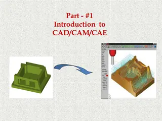
CAD/CAM Data Exchange Formats: Evolution and Importance
Explore the evolution of CAD/CAM data exchange formats, from graphics and data standards to the transfer of modeling data like shape, non-shape, design, and manufacturing information. Learn about common data exchange formats like IGES and PDES, essential for integrating and automating the design and manufacturing process in engineering.

Download Presentation

Please find below an Image/Link to download the presentation.
The content on the website is provided AS IS for your information and personal use only. It may not be sold, licensed, or shared on other websites without obtaining consent from the author. If you encounter any issues during the download, it is possible that the publisher has removed the file from their server.
You are allowed to download the files provided on this website for personal or commercial use, subject to the condition that they are used lawfully. All files are the property of their respective owners.
The content on the website is provided AS IS for your information and personal use only. It may not be sold, licensed, or shared on other websites without obtaining consent from the author.
E N D
Presentation Transcript
Part #4 CAD/CAM DATA EXCHANGE FORMATS Dec 2019
1. Graphics and Data Exchange Standards Till around 1973, software for producing graphics was mostly device dependent. Graphics software written for one type of hardware system was not portable to another type, or it became useless if the hardware was obsolete. Graphics standards were set to solve portability issues to render the application software device independent.
2. CAD/CAE/CAM Data Exchange Computer databases are now replacing paper blueprints in defining product geometry and non-geometry for all phases of product design, analysis, and manufacturing. It becomes increasingly important to find effective procedures for transferring data among CAD/CAE/CAM systems. The need to exchange modeling data is directly motivated by the need to integrate and automate the design and manufacturing process to obtain the maximum benefits from CAD/CAE/CAM systems.
Contd # Four types of Modeling Data to be transferred: 1) Shape data 2) Non shape data 3) Design data and 4) Manufacturing data. (1) Shape data > Consists of both geometrical and topological information as well as part features. > Entity attributes such as font, color, and layer as well as annotation is considered part of the entity geometrical information. > Topological information applies only to products described via solid modeling. > Features allow high-level concept communication about parts. Examples are hole, flange, web, pocket, chamfer, etc.
Contd (2) Non shape data includes graphics data such as shaded images, and model global data as measuring units of the database and the resolution of storing the database numerical values. (3) Design data has to do with the information that designers generate from geometric models for analysis purposes. e.g., mass property and finite element mesh data. (4) Manufacturing data consists of information such as tooling, NC tool paths, tolerance, process planning, tool design, and bill of materials.
Contd Commonly used CAD Data Exchange Format are: IGES (Initial Graphics Exchange Specification) and PDES (Product Data Exchange Using STEP) IGES is focused on CAD-to-CAD exchange where primarily shape and non shape data were to be transferred from one system to another. PDES is previous called Product Data Exchange Standard. It is for the exchange of complete product descriptions which covers the four types of modeling data (i.e., shape, non shape, design and manufacturing). Other data exchange interfaces include: STL, Neutral, SET, ECAD, VDA, STEP, PDGS, CATIA, Render, CGM, VRML, PATRAN, TIFF, etc.
Contd > For designing mechanical components and systems, one requires 3-D graphics capabilities for which GKS 3-D, PHIGS and DXF are suitable. > For 3-D graphics and animation, PHIGS is used It provides high interactivity, hierarchical data structuring, real time graphic data modification, and support for geometric transformations. > These standards provide the core of graphics including basic graphic primitives such as line, circle, arc, poly-lines, poly-markers, line-type and line-width, text, fill area for hatching and shading, locators for locating coordinates, valuators for real values for dimensioning, choice options and strings. > Around such standard primitives, almost all standard software for CAD is written. They also include the device drivers for standard plotters and display devices.
Contd Another comprehensive standard is IGES to enable the exchange of model databases among CAD/CAM systems. IGES contains more geometric entities such as, curves, surfaces, solid primitives, and Boolean (for Constructive Solid Geometry) operations. Wire-frame, surface modeling and solid modeling software can all be developed around IGES. It can transmit the property data associated with the drawings which helps in preparing, say, the bill of materials. Though these standards appear veiled or at the back end, they play a crucial role in creation of the application software.