Basic Hardware Verification Flow

Basic Hardware Verification Flow
Media IC and System Lab VLSI Crash Course 2018
Presentor: Yu Sheng Lin
●
What it the most important?
●
Beautiful and well reviewed code?
●
Smart engineer/architecture?
●
Complete test s.t. an average engineer cannot ruin the code?
Importance of Verification?
2
●
https://riscv-basics.com/
●
Verificcation and validation of processor designs can consume 75%
of total design time.
Example: ARM Think About Verification
3
●
I borrow the concept of UVM (Universal Verfication Methodology).
●
(We usually call this overall platform as
testbench
.)
What Forms Verification?
4
https://verificationacademy.com
Generate Golden Data
Your RTL
Drive data to
input ports
Monitor output ports
and collect data
●
Universal
Verfication Methodology.
●
What does
universal
means?
What Forms Verification?
5
Universal protocol largely enable code reuse!
●
Please review previous slides
Some Effective Protocols
6
●
The non-RTL parts can be implemented without Verilog!
●
This is usuallyed called co-simulation (co-sim).
The Non-RTL Parts
7
●
Instantiate (make a copy of) your module.
●
Driver
to send data.
●
Monitor
to receive and collect them.
●
Driver
and
Monitor
might follow specific protocols.
●
The collected data are compared by
Scoreboard
.
○
Golden (Mostly text file in Verilog, or programmatically when co-simed.)
○
Generated by your RTL module and collected by
Monitor
.
Brief Conclusions - A Testbench Must
8
●
Verilog provide external C accesses through VPI.
○
https://en.wikipedia.org/wiki/Verilog_Procedural_Interface
●
Based on C, people develops Java, Python... versions.
●
AFAIK, there are quite a lot Python based frameworks.
○
myhdl:
https://github.com/myhdl/myhdl
○
cocotb:
https://github.com/potentialventures/cocotb
○
nicotb:
https://github.com/johnjohnlin/nicotb
No Need for Verify RTL with Verilog
9
We focus on this today.
●
You have learnt that.
●
Why should you write testbench with Verilog if you can write in
Python?
●
Complete libraries: Numpy and DNN frameworks...
●
2
nd
~3
rd
place popular programming language.
●
Easy to learn and to write.
●
Not very fast compared with C
○
Do you care about performance in RTL simulation?
●
Native asynchronize language support.
●
It's cooooool.
Why Should I Write in Testbench Python?
10
●
I show you an example by me.
●
You can easily do with Python-Verilog simulation frameworks.
○
Simple GUI verfication with 50 lines Qt (7-seg display, button).
●
Used in NTUEE Digital Circuit Lab #1
Python Over Verilog on Verfication
11
●
For example, your code:
○
module Dut(
input clk,
input rst,
input irdy,
output logic iack,
input [10:0] iint,
output logic ordy,
input oack,
output logic [10:0] oint
);
●
You can test every module with the same API.
Interface Reuse → Testbench Reuse
12
Dut
Input
Output
Dataflow graph.
module Dut(
input irdy,
output logic iack,
input [10:0] iint,
output logic ordy,
input oack,
output logic [10:0] oint
);
Review the Image of UVM & protocol
13
●
input irdy,
output logic iack,
input [10:0] iint,
output logic ordy,
input oack,
output logic [10:0] oint
●
Group the red parts as a Master.
○
Master.Send(100)
●
Group the blue parts as a Slave.
○
Slave.Expect(101)
●
The same rules apply for Verilog-based verification.
○
But Verilog is less dynamic and ugly.
Testbench in Python
14
Master
Slave
●
Will this always work?
○
def main():
Master.Send(100)
Slave.Expect(101)
●
What if Send depends on Expect?
●
In Verilog we have can fork easily.
○
initial while (1) begin irdy = 1; @(posedge clk) ... end
initial while (1) begin oack = 0; @(posedge clk) ... end
●
In modern languages such as Python and JavaScript, asynchronized
execution is common.
Asynchronize(非同步)Issues
15
●
The asynchronize code could actually look like.
●
def main():
yield
cl
k
yield from
Master.Send(100)
Slave(
callback
=[Scoreboard.Expect, print])
1.
yield clk = @(posedge clk) in Verilog
2.
yield from = the function version wait
3.
callback: call the callbacks whenever data is monitored.
a.
print the monitored data and
b.
put the data to the checker (Scoreboard).
Asynchronize(非同步)Issues
16
Google Python "yield" and "yield
from" for more information.
●
Verilog controls the scheduling of Python code
●
The magic of
yield
keyword.
How to Combine Python and Verilog
17
def Master():
while True:
...
yield
def Slave():
while True:
...
yield
Fork([Slave, Master])
VPI
while (1) begin
@(posedge clk)
$PythonRun()
end
wire oack, iint...
●
Python code can read or write the Verilog signals.
○
Do you remember the +access
+rw
for ncverilog.
How to Combine Python and Verilog
18
while (1) begin
@(posedge clk)
$PythonRun()
end
wire oack, iint...
def Master():
while True:
...
yield
def Slave():
while True:
...
yield
Fork([Slave, Master])
VPI
A Small Co-Sim Example with Nicotb
●
You can find example here
https://github.com/johnjohnlin/nicotb
●
module Dut(
input clk,
input rst,
input irdy,
output logic iack,
input [10:0] iint,
output logic ordy,
input oack,
output logic [10:0] oint
);
●
If you send an
N
, then you can expect
0, 1, 2, 3…, N-1
19
Prepare a Verilog Wrapper
`Pos(rst_out, rst)
`PosIf(ck_ev, clk, rst)
always #1 clk = ~clk;
initial begin
clk = 0;
rst = 1;
#1 $NicotbInit();
#11 rst = 0;
#10 rst = 1;
#1000 $display("Timeout");$NicotbFinal();
$finish;
end
assign oack = ordy && ocanack;
Dut dut(clk,rst,irdy,iack,iint,ordy,oack,oint);
20
Declare your module here!
While you might not understand it,
this template requires almost no
modifications!
Declare your module here!
Prepare a Verilog Wrapper
`Pos(rst_out, rst)
`PosIf(ck_ev, clk, rst)
always #1 clk = ~clk;
initial begin
clk = 0;
rst = 1;
#1 $NicotbInit();
#11 rst = 0;
#10 rst = 1;
#1000
$display("Timeout");$NicotbFinal();
$finish;
end
assign oack = ordy && ocanack;
Dut dut(clk,rst,irdy,iack,iint,ordy,oack,oint);
21
You don't need to understand all
of them and mostly you only
modify the module to test and
simulation timeout.
(Prepare a Makefile)
NICOTB=~/nicotb/lib
IRUN=/opt/CAD/INCISIV/cur/tools.lnx86/bin/64bit/irun
%: %.sv
GLOG_logtostderr=1 \
TEST=$(if $(TEST),$(TEST),$@) \
TOPMODULE=$(if $(TOPMODULE),$(TOPMODULE),$@) \
PYTHONPATH=$(NICOTB)/python:`pwd` \
$(IRUN) +access+rw -loadvpi $(NICOTB)/cpp/nicotb.so:VpiBoot \
$(NICOTB)/verilog/Utils.sv $<
22
Modify according to your path
(irun = ncverilog)
Y
o
u
m
u
s
t
p
r
e
p
a
r
e
X
X
X
_
t
e
s
t
.
p
y
a
n
d
X
X
X
_
t
e
s
t
.
s
v
u
n
d
e
r
c
u
r
r
e
n
t
d
i
r
e
c
t
o
r
y
(
s
e
e
p
r
e
v
i
o
u
s
p
a
g
e
s
)
.
A
l
s
o
,
t
h
e
t
o
p
l
e
v
e
l
t
e
s
t
b
e
n
c
h
m
o
d
u
l
e
i
s
X
X
X
_
t
e
s
t
.
T
h
e
n
,
j
u
s
t
t
y
p
e
m
a
k
e
X
X
X
.
T
h
e
l
a
b
i
n
t
h
e
s
e
d
a
y
s
i
s
a
n
e
x
a
m
p
l
e
.
●
Prepare the RTL for design under test (DUT).
○
Not covered today.
●
Script for loading Python automatically (Makefile).
●
SystemVerilog wrapper.
○
Copy from examples.
●
Python testbench.
○
The most important one!
File Preparation Progress
23
O
O
O
X
Bridging Python and Verilog (Events)
●
Add these lines in Python
○
rst_out_ev, ck_ev = CreateEvents(["
rst_out
", "
ck_ev
",])
●
Add this lines in Verilog
○
`Pos(
rst_out
, rst)
`PosIf(
ck_ev
,
clk
, rst)
●
This means, whenever a
clk
posedge in Python,
ck_ev
is triggered
○
Mostly your submodules use 1 reset and clock and you just copy it.
●
That is,
○
Python
yield
ck_ev
= Verilog
@posedge
clk
●
However, simply writing yield in Python doesn't make thing easier.
○
We will explain later.
24
Bridging Python and Verilog (Wires)
●
API to connect Verilog wires
○
my_data_bus = CreateBus((
("", "a_signal", (4,2)),("dut", "sig"),("dut", "sig2"),))
●
The Verilog to be connected
○
logic [7:0] a_signal [4][2];
DUT my_dut(
.clk(clk),
.sig(sig)
)
25
hierarchy: toplevel → ""
name: a_signal
shape: (4,2)
Bridging Python and Verilog (Wires)
●
API to connect Verilog wires
○
my_data_bus = CreateBus((
("", "a_signal", (4,2)),("dut", "sig"),("dut", "sig2"),))
●
The Verilog to be connected
○
logic [7:0] a_signal [4][2];
DUT my_dut(
.clk(clk),
.sig(sig)
)
26
hierarchy: "dut" (nested: "dut.a.b")
name: sig
shape: not a array
Bridging Python and Verilog (Wires)
●
API to connect Verilog wires
○
my_data_bus = CreateBus((
("", "a_signal", (4,2)),("dut", "sig"),("dut", "sig2"),))
●
The Verilog to be connected
○
logic [7:0] a_signal [4][2];
DUT my_dut(
.clk(clk),
.sig(sig)
)
27
You don't have to connect sig2 to
the toplevel since Verilog allows
hierarchy access.
Access Verilog Wires in Python
●
my_data_bus = CreateBus((
("", "a_signal", (4,2)),("dut", "sig"),("dut", "sig2"),))
my_data_bus.Read()
my_data_bus.Write()
●
my_data_bus.a_signal.value → Numpy array of shape (4,2)
●
my_data_bus.sig.value → Numpy array of shape (1,)
●
my_data_bus.sig2.value → Numpy array of shape (1,)
28
Some Notes
●
Make use of Python unpack easily.
○
a = CreateBus(A)
b = CreateBus(B)
c = CreateBus(C)
a, b, c = CreateBus
es
([A, B, C])
●
This is the method of Nicotb, every framework has its method
connecting Verilog to Python (or whatever).
29
Short Conclusions
●
Connect to Verilog wires.
○
a = CreateBus((
("", "a_signal", (4,2)),("dut", "sig"),("dut", "sig2"),))
a, b, c = CreateBus
es
([..., ..., ...])
a.Read()
a.Write()
●
Access Verilog wires (32-bit limitation).
○
a.a_signal.value
→ 4x2 Numpy array
○
a.values.a_signal
→ Equivalent
30
Short Conclusions
●
Connect to Verilog events
○
rst_out_ev, ck_ev = CreateEvents(["
rst_out
", "
ck_ev
",])
yield ck_ev
○
`Pos(
rst_out
, rst)
`PosIf(
ck_ev
,
clk
, rst)
@(posedge clk)
31
Is That All?
●
If you
ONLY
know these, it doesn't make things easier.
○
yield clk
a.data.value[3:4] = 100
a.Write()
yield clk
●
Protocol based verification is the true keypoint!
32
●
Our toplevel module.
○
module Dut(
input clk,
input rst,
input irdy,
output logic iack,
input [10:0] iint,
output logic ordy,
input oack,
output logic [10:0] oint
);
●
Input data: N
●
Output data: 0, 1, 2, ..., N
●
Test data: input 0, 8, 7
Review Our Initial Problem
33
Dut
Input
Output
Dataflow graph.
●
First, you need to create the buses
○
irdy = CreateBus((("dut", "irdy")))iack = CreateBus((("dut", "iack")))iint = CreateBus((("dut", "iint")))ordy = CreateBus((("dut", "ordy")))oack = CreateBus((("dut", "oack")))oint = CreateBus((("dut", "oint")))●
Then, construct the classes in Python.
○
master = TwoWire.Master(
irdy, iack, iint
, ck_ev, A=1, B=5)
slave = TwoWire.Slave(
ordy, oack, oint
, ck_ev, callbacks=[
test.Get
]
)
Convert Bus into Protocol
34
●
Generate golden data for
Scoreboard
(not today's main issue).
○
Ns = np.array([0,8,7], dtype=np.int32)
# this create a column vector [0, 0, 1, 2, ..., 8, 0, 1, ..., 7]
golden = np.concatenate([
np.arange(N+1, dtype=np.int32) for N in Ns
])[:,np.newaxis]
test.Expect((golden,))
●
What should I
Expect
?
Check at Scoreboard
35
●
Look at the data bus.
○
ordy = CreateBus((("dut", "ordy")))oack = CreateBus((("dut", "oack")))oint = CreateBus((("dut", "oint")))●
Slave put that to
Scoreboard
.
○
st = Stacker(
1+9+8
, [bg.Get])
# PS: 1+9+8+=18
bg = BusGetter(callbacks=[st.Get])
slave = TwoWire.Slave(
ordy, oack,
oint
, ck_ev, callbacks=[
bg
.Get]
)
●
oint is a bus with one scalar (aka, not an array), so you get a tuple
of size ([18, 1],).
Data Format in Nicotb
36
The actual code is slightly more
complex than above pages, while
you can just copy and modify.
●
Look at the data bus.
○
oint = CreateBus((
("dut", "aaa")("dut", "bbb", (1,))("dut", "ccc", (12,3))))
●
In this example, the tuple size is ([18, 1], [18, 1], [18, 12, 3]).
Data Format in Nicotb
37
●
Look at the data bus.
○
golden = np.concatenate([
np.arange(N+1, dtype=np.int32) for N in Ns
])[:,np.newaxis]
test.Expect((golden,))
●
golden is a tuple of size ([18, 1],).
●
np.concatenate generate a array of size [18,], namely a row vector.
●
The [:, np.newaxis] is the standard method converting Numpy row
vector to a column vector (vertical one).
Back to Our Example
38
●
Prepare the RTL for design under test (DUT).
●
Script for loading Python automatically (Makefile).
●
SystemVerilog wrapper.
●
Python testbench.
○
Prepare input data and golden (it's your task).
○
Send the data.
○
Check the data at
scoreboard
.
We are Almost Done!
39
O
O
O
△
O
X
O
O
X
O
O
O
Drive Verilog Wire In Python (Quite Easy!)
master = TwoWire.Master(irdy, iack, iint, ck_ev, A=1, B=5)
values = master.values
def it():
for N in Ns:
values.iint[0] = N
yield values
yield from master.SendIter(it())
yield from master.SendIter(it(), latency=100)
40
Access data bus by name
values.iint is a Numpy array of size (1,)
This randomly drive the input.
This drive data every 100 cycles.
Probability = A/B (default = 1/5)
Note
values = master.values
def it():
for N in Ns:
values.iint[0] = N
yield values
yield from master.SendIter(it
()
)
yield from master.SendIter(it
()
, latency=100)
41
This part is only Python generator syntax,
it has no relationship with waiting Verilog
posedge!!!
Every 100 cycles (ignore probability)
●
Introduce the
idea
behind SystemVerilog UVM.
●
With Python, you can do the same thing much easily.
●
We introduce Nicotb today.
○
Document:
https://johnjohnlin.github.io/nicotb/
●
And there are many choices.
○
myhdl:
https://github.com/myhdl/myhdl
○
cocotb:
https://github.com/potentialventures/cocotb
Conclusions
42
Media IC and System Lab VLSI Crash Course 2018
Presentor: Shih Yi Wu
Practice Time
43
Lab2
44
Img
Img
N_IMG =16
80
120
8b pixel_data [3]
pixel_tag
ISE (Top)
2b o_type
5b o_tag
Sorter
Counter
img_tag, img_type
img_num, img_sum
Sorter_test
testbench
(already done (ref))
45
Sorter
clk
rst
img_valid
img_tag
img_type
img_num
o_valid
2b o_type
5b o_tag
Host
(Testbench)
img_sum
Counter_test
testbench
(todo)
46
Counter
clk
rst
img_valid
img_tag
img_type
img_num
pixel_valid
pixel_ready
pixel_data [3]
Host
(Testbench)
img_sum
pixel_tag
Top_test
testbench
(todo)
+
top module wire connection
(todo)
47
ISE (Top)
?
clk
rst
pixel_valid
pixel_ready
8b pixel_data [3]
5b pixel_tag
o_valid
2b o_type
5b o_tag
Host
(Testbench)
Counter
Counter
RTL verification (Review)
●
Prepare the RTL for design under test (DUT).
●
Script for loading Python automatically (Makefile).
●
SystemVerilog wrapper.
●
Python testbench.
○
Prepare input data and golden.
○
Send data.
○
Check the data at scoreboard.
48
module DUT(
input clk,
input sig,
input sig2
)...
logic [7:0] a_signal [4][2];
DUT my_dut(
.clk(clk)
)
1.
Connecting Verilog Wire (Ref:
Bridging python and Verilog
)
function
CreateBus, CreateBuses
my_data_bus
= CreateBus(
(
("", "a_signal", (4,2)),("dut", "sig"),("dut", "sig2"),)
)
Python testbench -- sending data (1/3)
49
python: xxx_test.py
system verilog: xxx_test.sv
system verilog: DUT.sv
2. Determine the protocol
(
i_valid
,
i_data
) = CreateBuses([(
(
("dut", "src_valid"),)
,
(
("dut", "i_data"),)
,
])
Python testbench -- sending data (2/3)
50
(
i_valid
,
i_rdy
,
i_data
) = CreateBuses([(
(
("dut", "src_valid"),)
,
(
("dut", "src_ready"),)
,
(
("dut", "i_data"),)
,
])
TwoWire.Master(
i_valid
,
i_rdy
,
i_data
, ck_ev)
OneWire.Master(
i_valid
,
i_data
, ck_ev)
2 - wire protocol
1 - wire protocol
Python testbench -- sending data (2/3)
2. Determine the protocol
T
woWire.Master(
i_valid
,
i_ready
,
i_data
, ck_ev, A=1, B=5)
OneWire.Master(
i_valid
,
i_data
, ck_ev, A=1, B=5)
TwoWire.Slave(
o_valid
,
o_ready
,
o_data
, ck_ev, callbacks=[bg.Get])
OneWire.Slave(
o_valid
,
o_data
, ck_ev, callbacks=[bg.Get])
51
3. Sending data from python to Verilog (Ref:
Drive Verilog Wire In Python
)
(
i_valid
,
i_data
) = CreateBuses([(
(("dut", "src_valid"),),(("data
"),),
])
master = OneWire.Master(i_valid,
i_data
, ck_ev)
mdata = master.values
...
mdata.
data
[0] = Img_r
mdata.
data
[1] = Img_g
mdata.
data
[2] = Img_b
…
Python testbench -- sending data (2/2)
52
logic [7:0]
data
[3];
system verilog: xxx_test.sv
Python testbench --
Check the data at scoreboard
Ref:
Check at Scoreboard
Notice the oder of the wire and the golden.
53
scb = Scoreboard("ISE")test = scb.GetTest(f"Sorter")
st = Stacker(
N_IMG
, callbacks=[test.Get])
bg
= BusGetter(callbacks=[st.Get])
# Construct slave (monitor) and connect slave to the scoreboard.
slave = OneWire.Slave(ovalid, odata, ck_ev, callbacks=[
bg
.Get])
# Check the data at slave.
# This create a tuple of two column vectors of size 16.
# The first one is o_tag, and the second one is o_type.
test.Expect(
(answer[:,1,np.newaxis], answer[:,0,np.newaxis])
)
golden numebr
(N_IMG == 16)
golden
Things you should know before you start
1.
There is a reference python testbench (
./sim/Sorter_test.py
)
2.
type
make sorter
under
./sim
→ it should work!
3.
All golden data are prepared (./sim/MyModel.py)
4.
Files you need to edit and the execution cmd:
54
V
e
r
i
l
o
g
:
=
=
=
=
=
=
=
=
=
=
=
=
=
=
=
=
=
=
=
=
=
=
=
=
=
=
=
=
=
=
=
=
=
=
=
=
=
=
=
=
=
=
=
=
=
=
=
=
=
=
=
=
=
=
./sim/Counter_test.py
(Testbench)
→ make Counter
./design/Top.v
(Wire Connection)
./sim/Top_test.py
(Testbench)
→ make USE_VERILOG=true top
S
y
s
t
e
m
V
e
r
i
l
o
g
:
=
=
=
=
=
=
=
=
=
=
=
=
=
=
=
=
=
=
=
=
=
=
=
=
=
=
=
=
=
=
=
=
=
=
=
=
=
=
=
=
=
=
=
=
=
=
=
=
=
=
=
=
=
=
./sim/Counter_test.py
(Testbench)
→ make Counter
./design/Top.sv
(Wire Connection)
./sim/Top_test.py
(Testbench)
→ make top
This content delves into the significance of verification in hardware design, emphasizing the need for meticulous code review, skilled engineers, and comprehensive testing practices. It explores the Universal Verification Methodology (UVM) and various effective protocols for ensuring robust verification processes in VLSI design. The discussion covers the utilization of testbenches, RTL generation, and non-RTL parts implementation, providing insights into creating a thorough verification framework.

Uploaded on Feb 16, 2025 | 0 Views
Download Presentation

Please find below an Image/Link to download the presentation.
The content on the website is provided AS IS for your information and personal use only. It may not be sold, licensed, or shared on other websites without obtaining consent from the author.If you encounter any issues during the download, it is possible that the publisher has removed the file from their server.
You are allowed to download the files provided on this website for personal or commercial use, subject to the condition that they are used lawfully. All files are the property of their respective owners.
The content on the website is provided AS IS for your information and personal use only. It may not be sold, licensed, or shared on other websites without obtaining consent from the author.
E N D
Presentation Transcript
Basic Hardware Verification Flow Media IC and System Lab VLSI Crash Course 2018 Presentor: Yu Sheng Lin
Importance of Verification? What it the most important? Beautiful and well reviewed code? Smart engineer/architecture? Complete test s.t. an average engineer cannot ruin the code? 2
Example: ARM Think About Verification https://riscv-basics.com/ Verificcation and validation of processor designs can consume 75% of total design time. 3
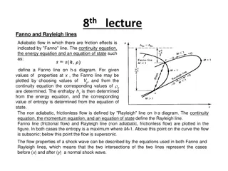
What Forms Verification? I borrow the concept of UVM (Universal Verfication Methodology). (We usually call this overall platform as testbench.) Your RTL https://verificationacademy.com Generate Golden Data Monitor output ports and collect data Drive data to input ports 4
What Forms Verification? Universal Verfication Methodology. What does universal means? Universal protocol largely enable code reuse! 5
Some Effective Protocols Please review previous slides 6
The Non-RTL Parts The non-RTL parts can be implemented without Verilog! This is usuallyed called co-simulation (co-sim). 7
Brief Conclusions - A Testbench Must Instantiate (make a copy of) your module. Driver to send data. Monitor to receive and collect them. Driver and Monitor might follow specific protocols. The collected data are compared by Scoreboard. Golden (Mostly text file in Verilog, or programmatically when co-simed.) Generated by your RTL module and collected by Monitor. 8
No Need for Verify RTL with Verilog Verilog provide external C accesses through VPI. https://en.wikipedia.org/wiki/Verilog_Procedural_Interface Based on C, people develops Java, Python... versions. AFAIK, there are quite a lot Python based frameworks. myhdl: https://github.com/myhdl/myhdl cocotb: https://github.com/potentialventures/cocotb nicotb: https://github.com/johnjohnlin/nicotb We focus on this today. 9
Why Should I Write in Testbench Python? You have learnt that. Why should you write testbench with Verilog if you can write in Python? Complete libraries: Numpy and DNN frameworks... 2nd~3rdplace popular programming language. Easy to learn and to write. Not very fast compared with C Do you care about performance in RTL simulation? Native asynchronize language support. It's cooooool. 10
Python Over Verilog on Verfication I show you an example by me. You can easily do with Python-Verilog simulation frameworks. Simple GUI verfication with 50 lines Qt (7-seg display, button). Used in NTUEE Digital Circuit Lab #1 11
Interface Reuse Testbench Reuse For example, your code: Input Dut Output module Dut( input clk, input rst, input irdy, output logic iack, input [10:0] iint, output logic ordy, input oack, output logic [10:0] oint Dataflow graph. ); You can test every module with the same API. 12
Review the Image of UVM & protocol module Dut( input irdy, output logic iack, input [10:0] iint, output logic ordy, input oack, output logic [10:0] oint ); 13
Testbench in Python input irdy, output logic iack, input [10:0] iint, output logic ordy, input oack, output logic [10:0] oint Master Slave Group the red parts as a Master. Master.Send(100) Group the blue parts as a Slave. Slave.Expect(101) The same rules apply for Verilog-based verification. But Verilog is less dynamic and ugly. 14
AsynchronizeIssues Will this always work? def main(): Master.Send(100) Slave.Expect(101) What if Send depends on Expect? In Verilog we have can fork easily. initial while (1) begin irdy = 1; @(posedge clk) ... end initial while (1) begin oack = 0; @(posedge clk) ... end In modern languages such as Python and JavaScript, asynchronized execution is common. 15
AsynchronizeIssues The asynchronize code could actually look like. def main(): yield clk yield from Master.Send(100) Slave(callback=[Scoreboard.Expect, print]) 1. yield clk = @(posedge clk) in Verilog 2. yield from = the function version wait 3. callback: call the callbacks whenever data is monitored. a. print the monitored data and b. put the data to the checker (Scoreboard). Google Python "yield" and "yield from" for more information. 16
How to Combine Python and Verilog Verilog controls the scheduling of Python code The magic of yield keyword. def Master(): while True: ... yield while (1) begin @(posedge clk) $PythonRun() end VPI def Slave(): while True: ... yield wire oack, iint... Fork([Slave, Master]) 17
How to Combine Python and Verilog Python code can read or write the Verilog signals. Do you remember the +access+rw for ncverilog. def Master(): while True: ... yield while (1) begin @(posedge clk) $PythonRun() end VPI def Slave(): while True: ... yield wire oack, iint... Fork([Slave, Master]) 18
A Small Co-Sim Example with Nicotb You can find example here https://github.com/johnjohnlin/nicotb module Dut( input clk, input rst, input irdy, output logic iack, input [10:0] iint, output logic ordy, input oack, output logic [10:0] oint ); If you send an N, then you can expect 0, 1, 2, 3 , N-1 19
Prepare a Verilog Wrapper Declare your module here! `Pos(rst_out, rst) `PosIf(ck_ev, clk, rst) always #1 clk = ~clk; initial begin clk = 0; rst = 1; #1 $NicotbInit(); #11 rst = 0; #10 rst = 1; #1000 $display("Timeout"); $NicotbFinal(); $finish; end While you might not understand it, this template requires almost no modifications! Declare your module here! assign oack = ordy && ocanack; Dut dut(clk,rst,irdy,iack,iint,ordy,oack,oint); 20
Prepare a Verilog Wrapper `Pos(rst_out, rst) `PosIf(ck_ev, clk, rst) always #1 clk = ~clk; initial begin clk = 0; rst = 1; #1 $NicotbInit(); #11 rst = 0; #10 rst = 1; #1000 $display("Timeout"); $NicotbFinal(); $finish; end You don't need to understand all of them and mostly you only modify the module to test and simulation timeout. assign oack = ordy && ocanack; Dut dut(clk,rst,irdy,iack,iint,ordy,oack,oint); 21
Modify according to your path (irun = ncverilog) (Prepare a Makefile) NICOTB=~/nicotb/lib IRUN=/opt/CAD/INCISIV/cur/tools.lnx86/bin/64bit/irun %: %.sv GLOG_logtostderr=1 \ TEST=$(if $(TEST),$(TEST),$@) \ TOPMODULE=$(if $(TOPMODULE),$(TOPMODULE),$@) \ PYTHONPATH=$(NICOTB)/python:`pwd` \ $(IRUN) +access+rw -loadvpi $(NICOTB)/cpp/nicotb.so:VpiBoot \ $(NICOTB)/verilog/Utils.sv $< You must prepare XXX_test.py and XXX_test.sv under current directory (see previous pages). Also, the top level testbench module is XXX_test. Then, just type make XXX. The lab in these days is an example. 22
File Preparation Progress O Prepare the RTL for design under test (DUT). Not covered today. O Script for loading Python automatically (Makefile). SystemVerilog wrapper. O Copy from examples. X Python testbench. The most important one! 23
Bridging Python and Verilog (Events) Add these lines in Python rst_out_ev, ck_ev = CreateEvents(["rst_out", "ck_ev",]) Add this lines in Verilog `Pos(rst_out, rst) `PosIf(ck_ev, clk, rst) This means, whenever a clk posedge in Python, ck_ev is triggered Mostly your submodules use 1 reset and clock and you just copy it. That is, Python yield ck_ev = Verilog @posedge clk However, simply writing yield in Python doesn't make thing easier. We will explain later. 24
Bridging Python and Verilog (Wires) API to connect Verilog wires my_data_bus = CreateBus(( ("", "a_signal", (4,2)), ("dut", "sig"), ("dut", "sig2"), )) hierarchy: toplevel "" name: a_signal shape: (4,2) The Verilog to be connected logic [7:0] a_signal [4][2]; DUT my_dut( .clk(clk), .sig(sig) ) 25
Bridging Python and Verilog (Wires) API to connect Verilog wires my_data_bus = CreateBus(( ("", "a_signal", (4,2)), ("dut", "sig"), ("dut", "sig2"), )) The Verilog to be connected hierarchy: "dut" (nested: "dut.a.b") name: sig shape: not a array logic [7:0] a_signal [4][2]; DUT my_dut( .clk(clk), .sig(sig) ) 26
Bridging Python and Verilog (Wires) API to connect Verilog wires my_data_bus = CreateBus(( ("", "a_signal", (4,2)), ("dut", "sig"), ("dut", "sig2"), )) You don't have to connect sig2 to the toplevel since Verilog allows hierarchy access. The Verilog to be connected logic [7:0] a_signal [4][2]; DUT my_dut( .clk(clk), .sig(sig) ) 27
Access Verilog Wires in Python my_data_bus = CreateBus(( ("", "a_signal", (4,2)), ("dut", "sig"), ("dut", "sig2"), )) my_data_bus.Read() my_data_bus.Write() my_data_bus.a_signal.value Numpy array of shape (4,2) my_data_bus.sig.value Numpy array of shape (1,) my_data_bus.sig2.value Numpy array of shape (1,) 28
Some Notes Make use of Python unpack easily. a = CreateBus(A) b = CreateBus(B) c = CreateBus(C) a, b, c = CreateBuses([A, B, C]) This is the method of Nicotb, every framework has its method connecting Verilog to Python (or whatever). 29
Short Conclusions Connect to Verilog wires. a = CreateBus(( ("", "a_signal", (4,2)), ("dut", "sig"), ("dut", "sig2"), )) a, b, c = CreateBuses([..., ..., ...]) a.Read() a.Write() Access Verilog wires (32-bit limitation). a.a_signal.value 4x2 Numpy array a.values.a_signal Equivalent 30
Short Conclusions Connect to Verilog events rst_out_ev, ck_ev = CreateEvents(["rst_out", "ck_ev",]) yield ck_ev `Pos(rst_out, rst) `PosIf(ck_ev, clk, rst) @(posedge clk) 31
Is That All? If you ONLY know these, it doesn't make things easier. yield clk a.data.value[3:4] = 100 a.Write() yield clk Protocol based verification is the true keypoint! 32
Review Our Initial Problem Our toplevel module. Input Dut Output module Dut( input clk, input rst, input irdy, output logic iack, input [10:0] iint, output logic ordy, input oack, output logic [10:0] oint Dataflow graph. ); Input data: N Output data: 0, 1, 2, ..., N Test data: input 0, 8, 7 33
Convert Bus into Protocol First, you need to create the buses irdy = CreateBus((("dut", "irdy"))) iack = CreateBus((("dut", "iack"))) iint = CreateBus((("dut", "iint"))) ordy = CreateBus((("dut", "ordy"))) oack = CreateBus((("dut", "oack"))) oint = CreateBus((("dut", "oint"))) Then, construct the classes in Python. master = TwoWire.Master(irdy, iack, iint, ck_ev, A=1, B=5) slave = TwoWire.Slave( ordy, oack, oint, ck_ev, callbacks=[test.Get] ) 34
Check at Scoreboard Generate golden data for Scoreboard (not today's main issue). Ns = np.array([0,8,7], dtype=np.int32) # this create a column vector [0, 0, 1, 2, ..., 8, 0, 1, ..., 7] golden = np.concatenate([ np.arange(N+1, dtype=np.int32) for N in Ns ])[:,np.newaxis] test.Expect((golden,)) What should I Expect? 35
Data Format in Nicotb Look at the data bus. ordy = CreateBus((("dut", "ordy"))) oack = CreateBus((("dut", "oack"))) oint = CreateBus((("dut", "oint"))) The actual code is slightly more complex than above pages, while you can just copy and modify. Slave put that to Scoreboard. st = Stacker(1+9+8, [bg.Get]) # PS: 1+9+8+=18 bg = BusGetter(callbacks=[st.Get]) slave = TwoWire.Slave( ordy, oack, oint, ck_ev, callbacks=[bg.Get] ) oint is a bus with one scalar (aka, not an array), so you get a tuple of size ([18, 1],). 36
Data Format in Nicotb Look at the data bus. oint = CreateBus(( ("dut", "aaa") ("dut", "bbb", (1,)) ("dut", "ccc", (12,3)) )) In this example, the tuple size is ([18, 1], [18, 1], [18, 12, 3]). 37
Back to Our Example Look at the data bus. golden = np.concatenate([ np.arange(N+1, dtype=np.int32) for N in Ns ])[:,np.newaxis] test.Expect((golden,)) golden is a tuple of size ([18, 1],). np.concatenate generate a array of size [18,], namely a row vector. The [:, np.newaxis] is the standard method converting Numpy row vector to a column vector (vertical one). 38
We are Almost Done! O Prepare the RTL for design under test (DUT). O Script for loading Python automatically (Makefile). O SystemVerilog wrapper. Python testbench. O Prepare input data and golden (it's your task). X Send the data. O Check the data at scoreboard. O O O O X 39
Drive Verilog Wire In Python (Quite Easy!) Probability = A/B (default = 1/5) master = TwoWire.Master(irdy, iack, iint, ck_ev, A=1, B=5) values = master.values def it(): for N in Ns: values.iint[0] = N yield values Access data bus by name values.iint is a Numpy array of size (1,) yield from master.SendIter(it()) This randomly drive the input. yield from master.SendIter(it(), latency=100) This drive data every 100 cycles. 40
Note values = master.values def it(): for N in Ns: This part is only Python generator syntax, it has no relationship with waiting Verilog posedge!!! values.iint[0] = N yield values yield from master.SendIter(it()) yield from master.SendIter(it(), latency=100) Every 100 cycles (ignore probability) 41
Conclusions Introduce the idea behind SystemVerilog UVM. With Python, you can do the same thing much easily. We introduce Nicotb today. Document: https://johnjohnlin.github.io/nicotb/ And there are many choices. myhdl: https://github.com/myhdl/myhdl cocotb: https://github.com/potentialventures/cocotb 42
Practice Time Media IC and System Lab VLSI Crash Course 2018 Presentor: Shih Yi Wu 43
Lab2 ISE (Top) Img 8b pixel_data [3] Counter pixel_tag Img 80 N_IMG =16 img_tag, img_type img_num, img_sum 120 Sorter 2b o_type 5b o_tag 44
Sorter_test testbench(already done (ref)) clk rst img_valid img_tag img_type Host Sorter (Testbench) img_num img_sum o_valid 2b o_type 5b o_tag 45
Counter_test testbench(todo) clk rst pixel_valid pixel_ready pixel_data [3] Host Counter pixel_tag (Testbench) img_valid img_tag img_type img_num img_sum 46
Top_test testbench(todo) + top module wire connection(todo) ISE (Top) clk rst Counter pixel_valid pixel_ready Host 8b pixel_data [3] ? (Testbench) 5b pixel_tag o_valid Counter 2b o_type 5b o_tag 47
RTL verification (Review) Prepare the RTL for design under test (DUT). Script for loading Python automatically (Makefile). SystemVerilog wrapper. Python testbench. Prepare input data and golden. Send data. Check the data at scoreboard. 48
Python testbench -- sending data (1/3) 1. Connecting Verilog Wire (Ref: Bridging python and Verilog) function CreateBus, CreateBuses system verilog: xxx_test.sv python: xxx_test.py logic [7:0] a_signal [4][2]; DUT my_dut( .clk(clk) ) my_data_bus = CreateBus(( ("", "a_signal", (4,2)), ("dut", "sig"), ("dut", "sig2"), )) system verilog: DUT.sv module DUT( input clk, input sig, input sig2 )... 49
Python testbench -- sending data (2/3) 2. Determine the protocol 2 - wire protocol 1 - wire protocol ( ( i_valid, i_rdy, i_data i_valid, i_data ) = CreateBuses([( ) = CreateBuses([( (("dut", "src_valid"),), (("dut", "src_valid"),), (("dut", "src_ready"),), (("dut", "i_data"),), (("dut", "i_data"),), ]) ]) TwoWire.Master(i_valid, i_rdy, i_data, ck_ev) OneWire.Master(i_valid, i_data, ck_ev) 50


Issues")
Issues")


")
")
")
")


")


")
")
")