AC Circuits: Impedance, Phase Angle, Resonant Frequency
Delve into the world of alternating currents (AC) circuits by learning how to calculate impedance, phase angle, resonant frequency, power, power factor, voltage, and current in an RLC series circuit. Explore circuit diagrams, understand the significance of resonant frequency, and discover the relationship between current and voltage in AC circuits.

Download Presentation

Please find below an Image/Link to download the presentation.
The content on the website is provided AS IS for your information and personal use only. It may not be sold, licensed, or shared on other websites without obtaining consent from the author.If you encounter any issues during the download, it is possible that the publisher has removed the file from their server.
You are allowed to download the files provided on this website for personal or commercial use, subject to the condition that they are used lawfully. All files are the property of their respective owners.
The content on the website is provided AS IS for your information and personal use only. It may not be sold, licensed, or shared on other websites without obtaining consent from the author.
E N D
Presentation Transcript
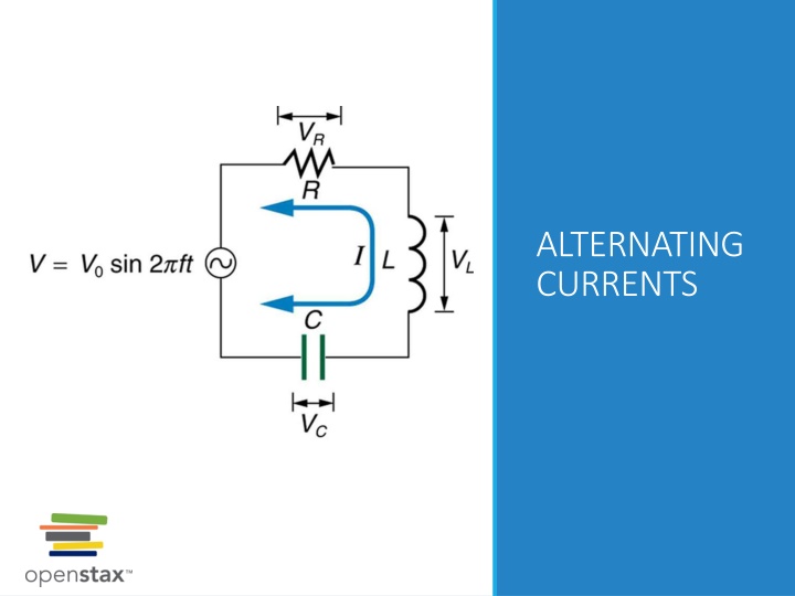
ALTERNATING CURRENTS
Todays objectives By the end of this lesson, you will be able to: Calculate the impedance, phase angle, resonant frequency, power, power factor, voltage, and/or current in a RLC series circuit. Draw the circuit diagram for an RLC series circuit. Explain the significance of the resonant frequency.
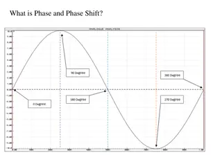
ac generator The emf of a generator is sent to a light bulb with the system of rings and brushes shown. The graph gives the emf of the generator as a function of time. emf0 is the peak emf. The period is ? = 1 / ? = 2? / ? , where ? is the frequency. Note that the script E stands for emf.
Resistor in an ac circuit ??= ??,0???(??) iR= ??,0???(??) ??,0= ???,0 Note: current and voltage are in phase with each other. (a) An AC voltage source in series with a resistor. (b) Graph of current and voltage across the resistor as functions of time, showing them to be exactly in phase.
rms current is a dc current that would produce the same power output as the actual ac circuit! rms current What is the average current in a resistor? ???= 0 Root-mean-square current ?0 ?2= ????= 2 ?0 ?2= ????= 2 For the resistor in an ac circuit ????= ????? 120-V ac means the rms voltage, not the maximum, which is 170 V!
Inductor in an ac circuit (a) An AC voltage source in series with an inductor having negligible resistance. (b) Graph of current and voltage across the inductor as functions of time.
Inductor in an ac circuit, continued Current lags behind the voltage by 90 degrees. ??,0= ????,0 or ??,???= ????,??? where ??= ?? (inductive reactance) Note: units of the inductive reactance are Ohms!
An inductor in an ac circuit example Suppose you want the current amplitude in a pure inductor in a radio receiver to be 250 A when the voltage amplitude is 3.60 V at a frequency of 1.60 MHz (corresponding to the upper end of the AM broadcast band). What inductive reactance is needed? What inductance? If the voltage amplitude is kept constant, what will be the current amplitude through the inductor at 16.0 Mhz?
Capacitor in an ac circuit ??,???= ????,??? ??,0= ????,0 where 1 ??= ?? is capacitive reactance
Capacitance in an ac circuit, continued Current leads the voltage by 90 degrees Remember ELI the ICE man mnemonics!
Phasors Phasor is a vector rotating around the origin of a coordinate system Length of the phasor corresponds to a maximum value of a current (or voltage) Projection of a phasor onto horizontal axis at a moment t equals the instantaneous value of a current (voltage). You can play with phasor simulation here: https://www.geogebra.org/m/hgyqrt8j
The L-R-C series circuit Many ac circuits used in practical applications involve resistance, capacitance, and inductance Can be analyzed with phasor diagram
The L-R-C series circuit, continued This graph shows the relationships of the voltages in an RLC circuit to the current. The voltages across the circuit elements add to equal the voltage of the source, which is seen to be out of phase with the current.
Impedance The combined effect of resistance R, inductive reactance XL, and capacitive reactance XC is defined to be impedance, an AC analogue to resistance in a DC circuit. with current, voltage, and impedance related by an AC version of Ohm s law:
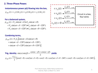
Resonance in an ac circuit How does an RLC circuit behave as a function of the frequency of the driving voltage source? The root-mean-square current will peak at a particular frequency at which Solving for the resonant frequency gives:
Resonance and the circuits resistance A graph of current versus frequency for two RLC series circuits differing only in the amount of resistance. Both have a resonance at f0, but that for the higher resistance is lower and broader. The driving AC voltage source has a fixed amplitude V0.