Series Resonance in Circuits
SERIES
R
E
SONA
N
CE
SERIES
R
E
SONA
N
T CI
R
C
U
IT
THE QUALITY
F
A
C
TOR (
Q )
The quality
f
a
c
tor
Q of
a se
r
ies r
e
sonant
c
ir
c
uit
is
d
e
f
i
n
e
d as the
r
a
t
io
of
t
he
re
a
c
tive
po
w
e
r
of
e
ither
the indu
c
tor
or
t
he
c
a
p
a
c
itor
t
o the
av
e
r
-
age
p
o
w
e
r
of
t
he
re
sistor
at r
e
sonan
ce
;
t
hat
is,
Q
l
will
a
lso
inc
r
ea
se
wh
e
n
f
inc
r
ea
s
e
for
low
f
r
e
qu
e
n
c
y
.
This
is
a
ppro
x
i
mat
e
l
y
true
f
o
r
the
low
r
a
nge
to
the
mid
ra
nge
of
fr
e
qu
e
n
c
i
e
s.
Un
f
o
r
tuna
t
e
l
y
,
how
e
v
e
r,
a
s
the
fr
e
qu
e
n
c
y
i
n
c
r
ea
s
e
s,
the
e
ff
ec
tive
r
e
sista
n
c
e
of
the
c
oil
will
a
lso
inc
r
e
a
s
e
,
due
p
r
im
a
ri
l
y
t
o
skin
e
f
f
ec
t
p
h
e
nomen
a
,
a
nd
t
he
r
e
sulti
n
g
Ql
will
d
e
c
r
e
a
s
e
.
I
n
a
ddition,
the
c
a
p
ac
itive
e
f
f
e
c
ts
b
e
t
w
ee
n
t
h
e
wi
n
din
g
s
will
in
c
r
e
a
s
e
,
f
u
rt
h
e
r
r
e
du
c
i
n
g
t
h
e
Ql
o
f
t
h
e
c
oil.
F
or this
r
e
a
son,
Ql
must
b
e
spe
c
ified
for
a
p
a
rti
c
ular
f
r
e
qu
e
n
c
y
o
r
f
r
e
q
u
e
n
c
y
r
a
n
g
e
.
F
or
wide
f
r
e
qu
e
n
c
y
a
ppli
ca
tions,
a
plot
of
Ql
v
e
rsus
f
r
e
qu
e
n
c
y
is
o
f
ten
p
r
ovided.
The
m
a
x
im
u
m
Ql
for
mo
s
t
c
o
mm
e
r
c
ial
l
y
a
v
a
il
a
ble
c
oils is less th
a
n 200, with
most h
a
ving a
ma
x
imum ne
a
r 100.
If
w
e
substi
t
ute
Z
T
VERSUS
F
REQU
E
N
C
Y
SELECTIV
I
TY
Th
er
e
is a
d
e
f
i
n
ite
r
an
g
e
of
f
re
qu
e
n
c
ies at
w
h
ich the
c
u
rre
nt is n
e
ar
its
m
ax
i
m
u
m
val
u
e
and
t
he
i
m
p
e
d
an
c
e
is at a
m
i
n
i
m
u
m
. T
h
ose f
r
e
qu
e
n
c
i
e
s co
r
re
spondi
n
g to
0
.707 of
t
he
m
ax
i
m
u
m
c
u
rr
e
nt a
r
e
c
all
e
d
t
he band
f
re
qu
e
n
c
ies,
c
utoff
f
re
qu
e
n
c
ies,
or
hal
f
-
p
o
w
e
r
f
re
qu
e
n
c
ies.
Th
e
y a
r
e
i
n
dica
t
e
d by f1
is
0.707 of
t
he
m
ax
i
m
um
c
u
r
re
nt
and
f
2 is
0.707 of
t
he
m
ax
i
m
um
c
u
r
re
nt
Hal
f
-
p
o
w
e
r
f
re
qu
e
n
c
ies
P
A
R
A
LLEL RESON
A
N
C
E
P
A
R
A
LLEL RESON
A
NT CIR
C
UIT
In series resonance circuits, the quality factor (Q) plays a crucial role, influencing the circuit's behavior at different frequencies. The Q factor varies with frequency, affecting impedance and selectivity. Explore the concept of Q, impedance, and selectivity in series resonance circuits through detailed explanations and illustrative images.

Download Presentation

Please find below an Image/Link to download the presentation.
The content on the website is provided AS IS for your information and personal use only. It may not be sold, licensed, or shared on other websites without obtaining consent from the author.If you encounter any issues during the download, it is possible that the publisher has removed the file from their server.
You are allowed to download the files provided on this website for personal or commercial use, subject to the condition that they are used lawfully. All files are the property of their respective owners.
The content on the website is provided AS IS for your information and personal use only. It may not be sold, licensed, or shared on other websites without obtaining consent from the author.
E N D
Presentation Transcript
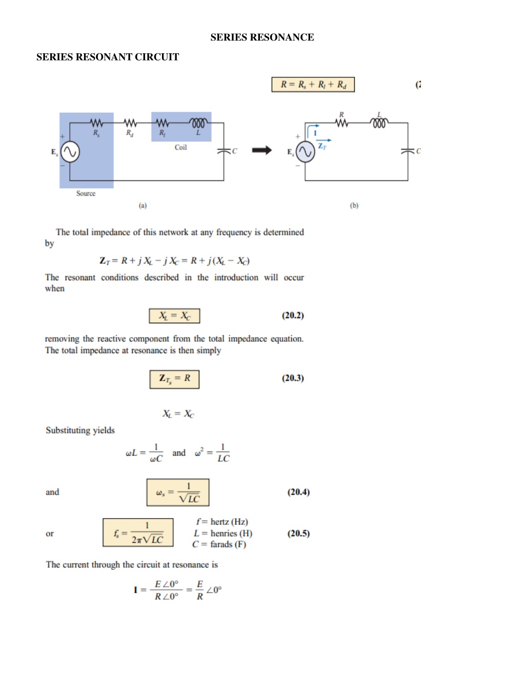
SERIES RESONANCE SERIES RESONANT CIRCUIT
THE QUALITY FACTOR ( Q ) The quality factor Q of a series resonant circuit is defined as the ratio of the reactive power of either the inductor or the capacitor to the aver- age power of the resistor at resonance; that is, Ql will also increase when f increase for low frequency. This is approximately true for the low range to the midrange of frequencies. Unfortunately, however, as the frequency increases, the effective resistance of the coil will also increase, due primarily to skin effect phenomena, and the resulting Ql will decrease. In addition, the capacitive effects between the windings will increase, further reducing the Ql of the coil. For this reason, Ql must be specified for a particular frequency or frequency range. For wide frequency applications, a plot of Ql versus frequency is often provided. The maximum Ql for most commercially available coils is less than 200, with most having a maximum near 100. If we substitute
SELECTIVITY There is a definite range of frequencies at which the current is near its maximum value and the impedance is at a minimum. Those frequencies corresponding to 0.707 of the maximum current are called the band frequencies, cutoff frequencies, or half-power frequencies. They are indicated by f1 is 0.707 of the maximum current and f2 is 0.707 of the maximum current Half-power frequencies
PARALLEL RESONANCE PARALLEL RESONANT CIRCUIT


")